[Solved] Communication from Gateway to Sensor node not working
-
Hello guys,
I have built temperature sensor DS18B20 using the example sketch, I also have a simple on off switch and LED on my sensor node. I am using Arduino Uno for both Gateway and sensor node.
My sensors work and show values on the MYSController. Now when I try to control LED using the MYSController, it doesn't work.
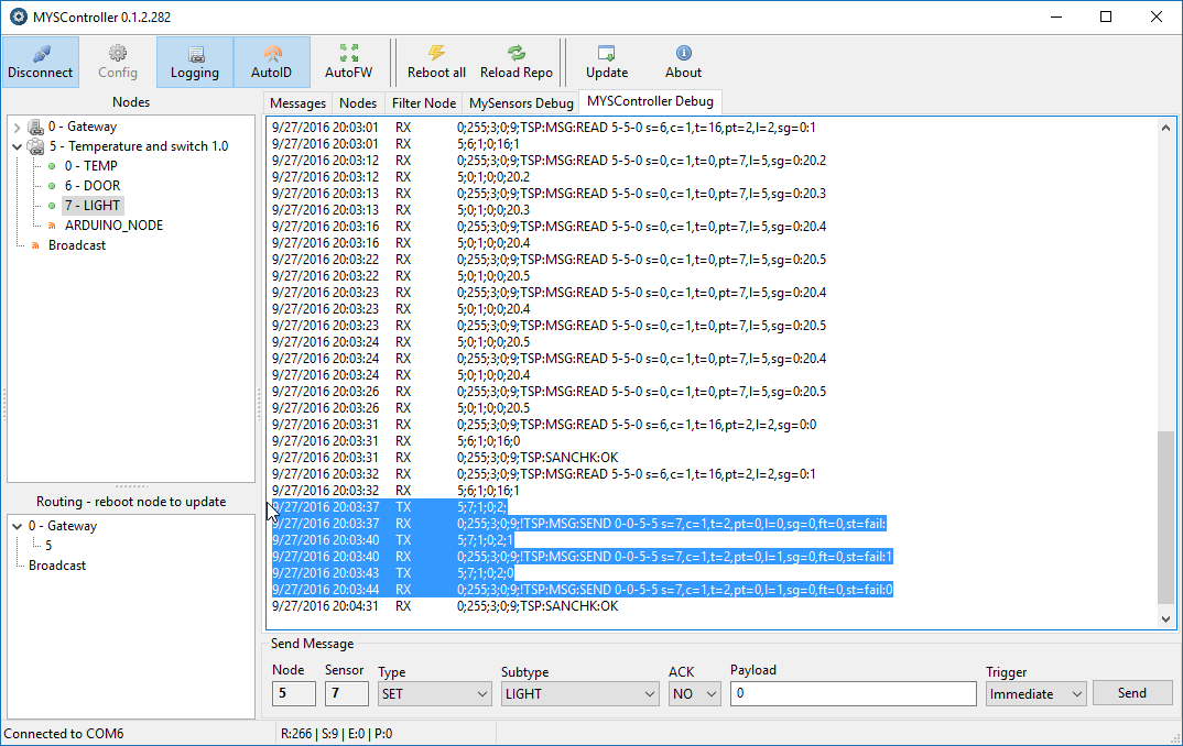
Here is the screenshot of what happens in MYSController:

I have tried with with and without payload. My code doesn't really need a payload to turn on or off the LED. It just toggles the state of an LED when it receives V_LIGHT message.
Here is my code for sensor node:
// Enable debug prints to serial monitor
#define MY_DEBUG

// Enable and select radio type attached
#define MY_RADIO_NRF24
//#define MY_RADIO_RFM69

#include <SPI.h>
#include <MySensors.h>
#include <DallasTemperature.h>
#include <OneWire.h>

#define COMPARE_TEMP 1 // Send temperature only if changed? 1 = Yes 0 = No

#define ONE_WIRE_BUS 3 // Pin where dallase sensor is connected
#define MAX_ATTACHED_DS18B20 16
unsigned long SLEEP_TIME = 30000; // Sleep time between reads (in milliseconds)
OneWire oneWire(ONE_WIRE_BUS); // Setup a oneWire instance to communicate with any OneWire devices (not just Maxim/Dallas temperature ICs)
DallasTemperature sensors(&oneWire); // Pass the oneWire reference to Dallas Temperature.
float lastTemperature[MAX_ATTACHED_DS18B20];
int numSensors=0;
bool receivedConfig = false;
bool metric = true;


// Initialize temperature message
MyMessage msg(0,V_TEMP);

//Initialize switch message
MyMessage msg1(6, V_TRIPPED);


void before()
{
  // Startup up the OneWire library
  sensors.begin();
}

void setup()
{
  // requestTemperatures() will not block current thread
  sensors.setWaitForConversion(false);

  // Setup the buttons for switch
  pinMode(2, INPUT);

  // Activate internal pull-ups
  digitalWrite(2, HIGH);

  //Set LED pin to OUTPUT
  pinMode (4, OUTPUT);

}

void presentation() {
  // Send the sketch version information to the gateway and Controller
  sendSketchInfo("Temperature and switch", "1.0");

  // Fetch the number of attached temperature sensors
  numSensors = sensors.getDeviceCount();

  // Present all sensors to controller
  //for (int i=0; i<numSensors && i<MAX_ATTACHED_DS18B20; i++) {
     present(0, S_TEMP);

     //preset the switch
     present(6, S_DOOR);

     //present LED
     present(7, S_LIGHT);

  }

void loop()
{
  // Fetch temperatures from Dallas sensors
  sensors.requestTemperatures();

  // query conversion time and sleep until conversion completed
  int16_t conversionTime = sensors.millisToWaitForConversion(sensors.getResolution());
  // sleep() call can be replaced by wait() call if node need to process incoming messages (or if node is repeater)
  sleep(conversionTime);

  // Read temperatures and send them to controller
  for (int i=0; i<numSensors && i<MAX_ATTACHED_DS18B20; i++) {

    // Fetch and round temperature to one decimal
    float temperature = static_cast<float>(static_cast<int>((getConfig().isMetric?sensors.getTempCByIndex(i):sensors.getTempFByIndex(i)) * 10.)) / 10.;

    // Only send data if temperature has changed and no error
    #if COMPARE_TEMP == 1
    if (lastTemperature[i] != temperature && temperature != -127.00 && temperature != 85.00) {
    #else
    if (temperature != -127.00 && temperature != 85.00) {
    #endif

      // Send in the new temperature
      send(msg.setSensor(i).set(temperature,1));
      // Save new temperatures for next compare
      lastTemperature[i]=temperature;
    }
  }
  //sleep(SLEEP_TIME);

  //Code for switch

  uint8_t value;
  static uint8_t sentValue=2;

  value = digitalRead(2);

  if (value != sentValue) {
     // Value has changed from last transmission, send the updated value
     send(msg1.set(value==HIGH ? 1 : 0));
     digitalWrite(8,!(digitalRead(8)));

     String string = "Value changed to: ";

     Serial.println(string += value);
     sentValue = value;
  }
 // Sleep until something happens with the sensor
  //sleep(0,CHANGE,0);
}

void receive(const MyMessage &message)
{

  Serial.println("Received command");
  //Check for the message from controller
  if (message.type==V_LIGHT)
  {
    digitalWrite(4, !digitalRead(4));
    Serial.println("LED status changed");
  }
}
For gateway I am using the example code without making any change. When I send command using MYSController, I can see RX LED blink on the Gateway Arduino but nothing on the sensor node serial monitor.
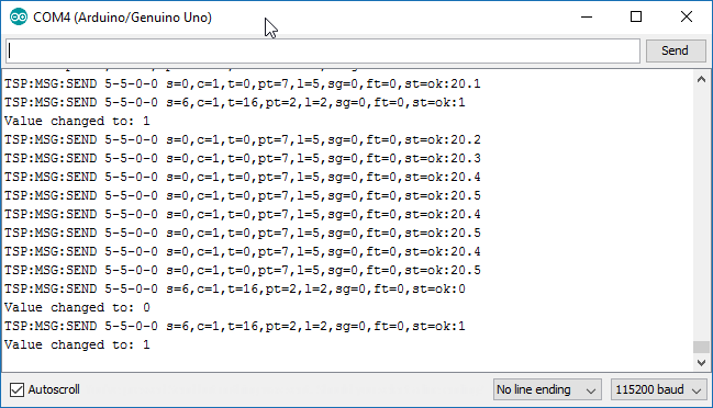
Serial Monitor for sensor node:

What am I doing wrong?
I will really appreciate the help.Thank You,
Vaibhav -
Looks like the radio communication is fine!?
What kind of hardware do you use to control LED? -
Looks like the radio communication is fine!?
What kind of hardware do you use to control LED?@sundberg84
I just have LED connected to the pin 4 of Arduino.
I have written code such that when receive() is executed the LED is toggled. -
@sundberg84
I just have LED connected to the pin 4 of Arduino.
I have written code such that when receive() is executed the LED is toggled.@palande.vaibhav - and when you recieve the command it doesnt turn on?
What does this mean?digitalWrite(4, !digitalRead(4));In the relaysketch its this;
digitalWrite(message.sensor-1+RELAY_1, message.getBool()?RELAY_ON:RELAY_OFF);Try HIGH/LOW on a normal led/blink sketch and see if that works.
-
@palande.vaibhav - and when you recieve the command it doesnt turn on?
What does this mean?digitalWrite(4, !digitalRead(4));In the relaysketch its this;
digitalWrite(message.sensor-1+RELAY_1, message.getBool()?RELAY_ON:RELAY_OFF);Try HIGH/LOW on a normal led/blink sketch and see if that works.
@sundberg84
No it doesn't turn on. And I even don't see anything on the serial monitor for the sensor node. I think I should be able to see the READ on the serial monitor for the sensor node. But I don't get that on there.digitalWrite(4, !digitalRead(4));This means,
digitalRead(4)------> Read the value at pin 4.
!-----> Toggle it, that is after reading the value, if it is 0 then make it one and if it is 1 make it 0.
digitalWrite(4,----> Write it back to pin 4.digitalWrite(message.sensor-1+RELAY_1, message.getBool()?RELAY_ON:RELAY_OFF);This line actually checks for the payload that comes with the received signal and makes RELAY_ON or RELAY_OFF decision accordingly.
So, I am doing much simpler task than relay example. I am trying to not even check what the received message says, I am just checking if I get the message or not and make LED toggle if I do get the message. -
@sundberg84
No it doesn't turn on. And I even don't see anything on the serial monitor for the sensor node. I think I should be able to see the READ on the serial monitor for the sensor node. But I don't get that on there.digitalWrite(4, !digitalRead(4));This means,
digitalRead(4)------> Read the value at pin 4.
!-----> Toggle it, that is after reading the value, if it is 0 then make it one and if it is 1 make it 0.
digitalWrite(4,----> Write it back to pin 4.digitalWrite(message.sensor-1+RELAY_1, message.getBool()?RELAY_ON:RELAY_OFF);This line actually checks for the payload that comes with the received signal and makes RELAY_ON or RELAY_OFF decision accordingly.
So, I am doing much simpler task than relay example. I am trying to not even check what the received message says, I am just checking if I get the message or not and make LED toggle if I do get the message.@palande.vaibhav
i think the answer is in the code// sleep() call can be replaced by wait() call if node need to process incoming messages (or if node is repeater) sleep(conversionTime);Replace sleep(); by wait();
During a sleep the GW does not receives the message acknowledge and thus claims the broadcast did fail.
-
@palande.vaibhav
i think the answer is in the code// sleep() call can be replaced by wait() call if node need to process incoming messages (or if node is repeater) sleep(conversionTime);Replace sleep(); by wait();
During a sleep the GW does not receives the message acknowledge and thus claims the broadcast did fail.
@BartE said:
@palande.vaibhav
i think the answer is in the code// sleep() call can be replaced by wait() call if node need to process incoming messages (or if node is repeater) sleep(conversionTime);Replace sleep(); by wait();
During a sleep the GW does not receives the message acknowledge and thus claims the broadcast did fail.
This worked.
Thanks a lot for the help. I guess I need to read stuff properly.Thanks for the help.
