💬 NModule
-
thanks for detailed explanation, I was always a bit skeptical towards those small batteries, but your module (and documentation) clears all doubts :)
Do you have any experience with OTA updates? I understand that it also needs custom boot-loader (sorry still not having enough understanding about all the things that are involved in making one node, a lot of new terms for me :) )@dakipro no sorry I'm not (yet) using OTA.
But yes you need a specific bootloader that will download the new code from the controller and update flash memory of the atmega. There are 2 solutions for this (sorry forgot the names of bootloaders but check the documentation):- a bootloader that needs an external flash chip to store the downloaded code. It's a constraint, but it allows the sensor to continue running during download and it will be "offline" only for a short time during memory copy & reboot
- a bootloader that will copy directly the new code to the flash memory. It means as soon as the sketch started to download your node is offline until all the sketch is downloaded. And if update fails, your old sketch is still gone
OTA also need some specific code to check for the updates.
-
Thanks :)
Then I guess all that is left is to motivate you to start OTA and improve it (finetune) it to nmodule :)
I used it for regular modules and it is really practical, but I never had much luck with optimizing modules for battery performance. I would get a half year/year with 2 AA batteries, which is not that good comparing with your tweaks for CR battery.Keep us updated on other modules, people are waiting for your tests to start ordering :)
C: OpenHAB2 with node-red on linux laptop
GW: Arduino Nano - W5100 Ethernet, Nrf24l01+ 2,4Ghz mqtt
GW: Arduino Mega, RFLink 433Mhz -
Thanks :)
Then I guess all that is left is to motivate you to start OTA and improve it (finetune) it to nmodule :)
I used it for regular modules and it is really practical, but I never had much luck with optimizing modules for battery performance. I would get a half year/year with 2 AA batteries, which is not that good comparing with your tweaks for CR battery.Keep us updated on other modules, people are waiting for your tests to start ordering :)
@dakipro for OTA I don't think there's much to do with batteries & OTA' Either the batteries allow continuous load (CR123, AAA, li-ion etc) or you just can't do it.
For battery life it's pretty simple but people keep choosing the wrong options and end up with poor battery life/instability etc etc. That's the reason I created the NModule: cheap and sure way to get a good battery life. Then I got a bit wild with the "shields" but that's another story :D
For other shields I'm making (slow) progress but I hope to take NModule, TH, Light/SSR, dual touch button, MiLight bridge and PWM boards out of the "work in progress" status during the next 2 weeks.
-
Hey @Nca78 I received the boards and components (yay!)
But... I connected three modules, and none of them works :(
They all have transport (radio?) fail like32 TSM:INIT
49 TSF:WUR:MS=0
81 !TSM:INIT:TSP FAIL
98 TSM:FAIL:CNT=1
114 TSM:FAIL:PDTI tried connecting radios from two different batches, I tried connecting only the radio and arduino, I tried powering it from separate powersupply and only debug via serial. I tried provided sketch and also tried dummy sketch from the examples. I tried using the CR battery, node works fine except that the radio doesn't start communicating.
I do measure 3V on the radio pins. I tried with and without radio cap.I am using chinese silicon mat to solder components on, I read somewhere that you use something similar *(not that I am spying on you :) ) but could it be that I am frying all the radios with static electricity?
I have used the mat before and it works fine with regular radios, nothing fried so far, but there is something preventing nodes from working :(Do you have any suggestions on how I can debug them and see what seems to be the problem?
C: OpenHAB2 with node-red on linux laptop
GW: Arduino Nano - W5100 Ethernet, Nrf24l01+ 2,4Ghz mqtt
GW: Arduino Mega, RFLink 433Mhz -
Hey @Nca78 I received the boards and components (yay!)
But... I connected three modules, and none of them works :(
They all have transport (radio?) fail like32 TSM:INIT
49 TSF:WUR:MS=0
81 !TSM:INIT:TSP FAIL
98 TSM:FAIL:CNT=1
114 TSM:FAIL:PDTI tried connecting radios from two different batches, I tried connecting only the radio and arduino, I tried powering it from separate powersupply and only debug via serial. I tried provided sketch and also tried dummy sketch from the examples. I tried using the CR battery, node works fine except that the radio doesn't start communicating.
I do measure 3V on the radio pins. I tried with and without radio cap.I am using chinese silicon mat to solder components on, I read somewhere that you use something similar *(not that I am spying on you :) ) but could it be that I am frying all the radios with static electricity?
I have used the mat before and it works fine with regular radios, nothing fried so far, but there is something preventing nodes from working :(Do you have any suggestions on how I can debug them and see what seems to be the problem?
Hello, @dakipro, can you show a picture of one of the board ?
Did you short the jumpers (JPOWER and JRDIO) if you're not using any regulators ?Yes I use a cheap silicon mat because it's so convenient, and I never had any problems with it all my radio worked.
-
Hey @Nca78 I received the boards and components (yay!)
But... I connected three modules, and none of them works :(
They all have transport (radio?) fail like32 TSM:INIT
49 TSF:WUR:MS=0
81 !TSM:INIT:TSP FAIL
98 TSM:FAIL:CNT=1
114 TSM:FAIL:PDTI tried connecting radios from two different batches, I tried connecting only the radio and arduino, I tried powering it from separate powersupply and only debug via serial. I tried provided sketch and also tried dummy sketch from the examples. I tried using the CR battery, node works fine except that the radio doesn't start communicating.
I do measure 3V on the radio pins. I tried with and without radio cap.I am using chinese silicon mat to solder components on, I read somewhere that you use something similar *(not that I am spying on you :) ) but could it be that I am frying all the radios with static electricity?
I have used the mat before and it works fine with regular radios, nothing fried so far, but there is something preventing nodes from working :(Do you have any suggestions on how I can debug them and see what seems to be the problem?
-
-
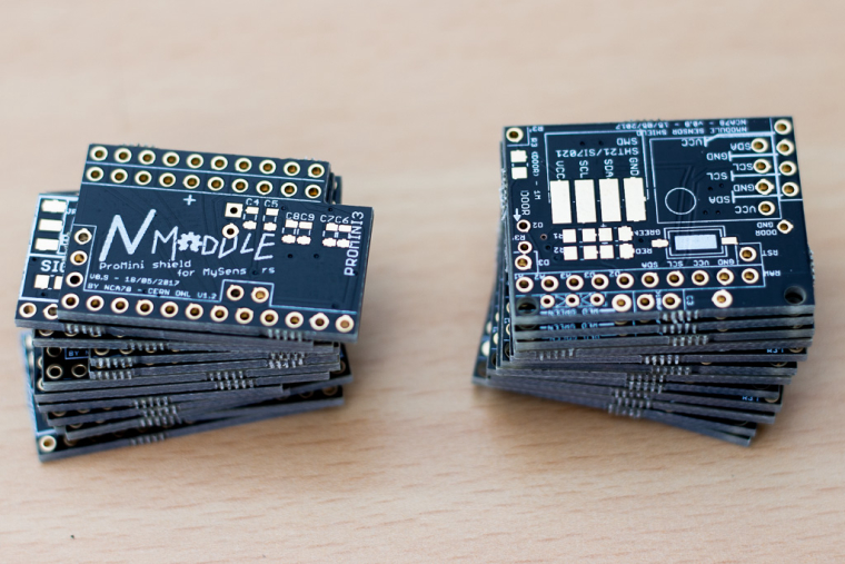
Looks as though the PA/LNA part of the silkscreen warning got largely obliterated by the solder pads.
-
Must I have a radio cap?
I connected the jumpers now quickly for a test (missed the part that I need them), but still same error49 TSF:WUR:MS=0
81 !TSM:INIT:TSP FAIL
98 TSM:FAIL:CNT=1
114 TSM:FAIL:PDT
10158 TSM:FAIL:RE-INIT
10174 TSM:INIT
10207 !TSM:INIT:TSP FAIL
10240 TSM:FAIL:CNT=2
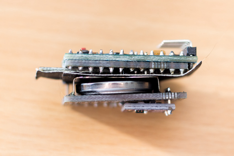
10256 TSM:FAIL:PDTHere is the photo of the board (a bit blurry, I can take it again if it helps)
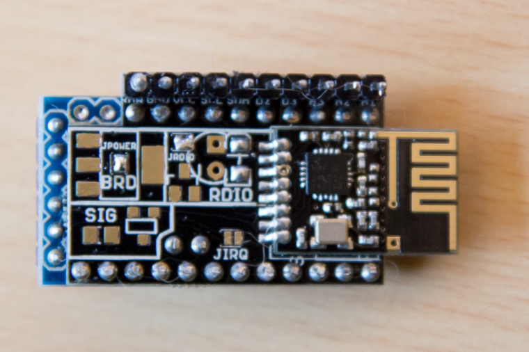
I am missing the radio cap as I was testing lest night without them, but I can solder them in a few hours and test again if you think it will help.
I connect power to the vcc pin of the "connection pins" right?
Radio is the one linked in the BOM from aliexpress
-
Must I have a radio cap?
I connected the jumpers now quickly for a test (missed the part that I need them), but still same error49 TSF:WUR:MS=0
81 !TSM:INIT:TSP FAIL
98 TSM:FAIL:CNT=1
114 TSM:FAIL:PDT
10158 TSM:FAIL:RE-INIT
10174 TSM:INIT
10207 !TSM:INIT:TSP FAIL
10240 TSM:FAIL:CNT=2
10256 TSM:FAIL:PDTHere is the photo of the board (a bit blurry, I can take it again if it helps)
I am missing the radio cap as I was testing lest night without them, but I can solder them in a few hours and test again if you think it will help.
I connect power to the vcc pin of the "connection pins" right?
Radio is the one linked in the BOM from aliexpress
-
checked between the pins, no radio pins are touching each other. Those hairs er most likely from the cat, got them cleaned after the photo.
I will try to make one more module in a few days and test.But to confirm, for the simplest module I need >4.7uF cap, pro mini and the radio, two jumpers (jpower and jrdio) and some mock sketch, and it should all work?
Have I missed some other jumper or resistor or some other component maybe?C: OpenHAB2 with node-red on linux laptop
GW: Arduino Nano - W5100 Ethernet, Nrf24l01+ 2,4Ghz mqtt
GW: Arduino Mega, RFLink 433Mhz -
checked between the pins, no radio pins are touching each other. Those hairs er most likely from the cat, got them cleaned after the photo.
I will try to make one more module in a few days and test.But to confirm, for the simplest module I need >4.7uF cap, pro mini and the radio, two jumpers (jpower and jrdio) and some mock sketch, and it should all work?
Have I missed some other jumper or resistor or some other component maybe?@dakipro no you're not missing anything now.
Cap is not even necessary at the moment don't worry about it.Problem is connection with radio so you have to make sure :
- VCC and GND pins of radio are correctly connected (seems it's done)
- SPI pins are correctly connected to the radio, check the "connecting the radio" page for the pinout on the pro mini, and radio module pinout. Then check continuity from radio connector to matching pin on radio side, you might have a soldering problem.
-
@dakipro you can also check the continuity between adjacents pins of the radio modules, it should be in MOmhs, if lower that could be a reason for failing communication too.
@dakipro you can also check the continuity between adjacents pins of the radio modules, it should be in MOmhs, if lower that could be a reason for failing communication too.
Just reading on computer instead of phone and I see you did it already, so except a connection problem with the SPI pins I don't see any reason for failure...
-
Thanks :)
Then I guess all that is left is to motivate you to start OTA and improve it (finetune) it to nmodule :)
I used it for regular modules and it is really practical, but I never had much luck with optimizing modules for battery performance. I would get a half year/year with 2 AA batteries, which is not that good comparing with your tweaks for CR battery.Keep us updated on other modules, people are waiting for your tests to start ordering :)
Thanks :)
Then I guess all that is left is to motivate you to start OTA and improve it (finetune) it to nmodule :)Just did OTA on a main powered NModule with MYSBootloader and it worked like a charm.
I will test with a battery (CR123) module at 1MHz now, and post a tutorial later. -
Thanks :)
Then I guess all that is left is to motivate you to start OTA and improve it (finetune) it to nmodule :)Just did OTA on a main powered NModule with MYSBootloader and it worked like a charm.
I will test with a battery (CR123) module at 1MHz now, and post a tutorial later. -
IT WORKS!! Life is worth living again...
I've assembled now fourth module and it works, only different thing I did is that I have soldered the radio and power jumpers before connecting the module together. It could be that without jumpers essential component of all electronics (white smoke) gets out of the radio, not sure what happened. But it works!I was struggling a bit to figure out all components needed and all the steps, it might be helpful to have a "short guide", this is for my own reference of what I did in order to get CR2032 module for using with TempHumDoor shield:
Components needed [nModule]: pro mini, radio, nmodule board, 1 capacitor for radio larger then 4.7uf (I har only 10uf, I have ordered 47uf for future modules).
Assembling process
- Burn 1mhz bootloader on pro mini
- solder two jumpers for jpower and jrdio
- solder the radio to the board
- Control that there is no connection between the radio pins, resistance is at least above 200Kohm (don't skip this part thinking it cannot happen to you, it will happen)
- Solder >4.7uf (f.eks. 10ud) smd.
- Solder all legs to arduino (except last two RXI and TX0, you will see them missing when you align nModule)
- Take off the plastic from the legs, before you solder it to the radio (do this BEFORE you solder it to the board)
- Solder arduino to nModule board
- Since the capacitor is very small, just check if there is no short between plus and minus (vcc and gnd) pins, as somehow I managed to short them on one module, it turned out that one of the caps was shorting it, probably by overhitting or something.
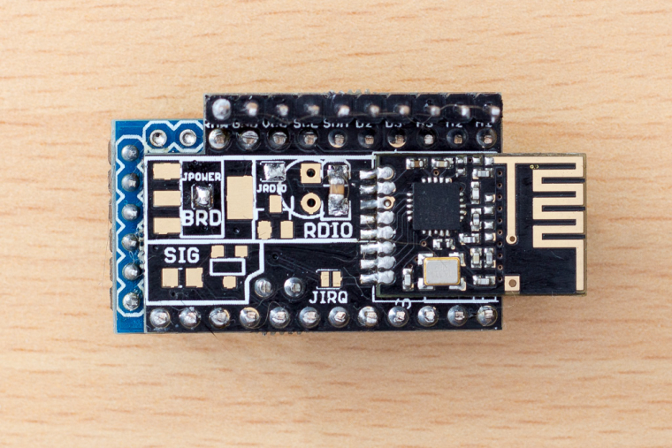
Upload mockMySensors sketch and check that node works properly (spare yourself a trouble, no point continuing further if this doesn't work) By this point you should have node looking like (better then) this:
TempHumidityLightDoor shield components: SMD SI7021 for temperature and humidity and a MAX44009 for light, two capacitors larger then 100uf (I used two of 100uf, waiting for 220 to come). And the work so far.
You basically solder these three/four components and the battery holder as described on the shield here https://www.openhardware.io/view/398/NModule-Temperature-Humidity-Light-Door-sensor-shield
I didn't yet solder LEDs, but they are accessible after assembling the module.
Then it looks like this: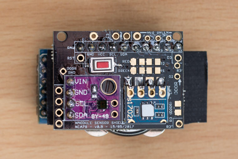
Now that nModule #1 is completed, you continue with other modules
-
If the "power" board is used, shall I keep the voltage regulator on Arduino? Without it, i think powering the board from RAW pin will not work.