nRF5 action!
-
@scalz hinted at it previously, but it looks like MyNewt OS might offer yet another way to do OTA updates. According to their posted information, it offers:
A open-source Bluetooth 5.0 stack (both Host & Controller), NimBLE, that completely replaces the proprietary SoftDevice on Nordic chipsets. (https://github.com/apache/mynewt-core/blob/master/README.md)
Apparentlly it runs on both the nRF52832 and the nRF52840.
@neverdie
1737 posts and counting
Spend hours reading this. Amazing journey so far. -
@toyman Micropython on the BBC micro:bit (which uses the nRF51822) has a Radio library that uses Nordic's proprietary radio modes and doesn't involve Bluetooth. I suppose the question is: what would be involved in getting it to run on the nRF52832 or the nRF52840. Seems like it would be substantially the same.
Faiing that, if I can directly manipulate the radio registers from miropython as I can from C, then it shouldn't be too hard to get at least minimal radio capability up and running from within micropython.
If I can get rudimentary radio communications working in micropython, then from there it should be easy to do OTA updates via REPL. I did some proof of concept to that effect on the micro:bit, but quickly ran out of memory--the micro:bit has only a total of 16K of RAM, so there's very little headroom to begin with. On the nRF52840, lack of RAM shouldn't be an issue.
@neverdie There are three ways to manipulate registers directly from Micropython:
-
Use machine.mem16
-
Use the decorator @micropython_viper
The Viper code emitter implements integer types and pointers, allowing to access memory and registers directly. -
Use the decorator @micropython.asm_thumb
Write your code in ARM assembler.
Problem: I don't know whether any of this is already implemented and works reliably in Micropython for nRF.
-
-
@neverdie
1737 posts and counting
Spend hours reading this. Amazing journey so far.@speechsupply this thread is golden. I was so empowered that was able to easily switch to nRF SDK and to start producing (semi) commercial BLE-ANT device
-
@speechsupply this thread is golden. I was so empowered that was able to easily switch to nRF SDK and to start producing (semi) commercial BLE-ANT device
@toyman
Yea, On monday I'll order a couple of nRF52840 EVAL boards. Any suggestion regarding what to get?
Looked at both the BMD-340-EVAL and ofcourse the NRF52840-DK -
@neverdie There are three ways to manipulate registers directly from Micropython:
-
Use machine.mem16
-
Use the decorator @micropython_viper
The Viper code emitter implements integer types and pointers, allowing to access memory and registers directly. -
Use the decorator @micropython.asm_thumb
Write your code in ARM assembler.
Problem: I don't know whether any of this is already implemented and works reliably in Micropython for nRF.
@uhrheber said in nRF5 action!:
@neverdie There are three ways to manipulate registers directly from Micropython:
-
Use machine.mem16
-
Use the decorator @micropython_viper
The Viper code emitter implements integer types and pointers, allowing to access memory and registers directly. -
Use the decorator @micropython.asm_thumb
Write your code in ARM assembler.
Problem: I don't know whether any of this is already implemented and works reliably in Micropython for nRF.
Thanks! We finally nailed it all the way down on this thread here: https://forum.micropython.org/viewtopic.php?f=12&t=5377
:smiley:
-
-
I see somewhat strange behaviour when using millis() for intervals.
I'm not sure it's my mistake, but one thing is that it seems that the millis rollover is around; 131.068.570 (36 hours)
When the rollover happens, it looks like it interrupts my sleep. Does that make sense?
sleep(digitalPinToInterrupt(PIR_Pin), CHANGE, LongSleep);Debug lines => (Temp / RH - Millis)
21.44 / 61.15 - 130977952
21.43 / 61.16 - 131008158
21.42 / 61.15 - 131038364
21.44 / 61.14 - 131068570
I woke up because I saw movement at: 26576
Sleep Duration : -131042000  Im going back to sleep for 150000
21.43 / 61.16 - 176822
20-10-2018 => its been ±36 hours laters, and he woke up again at the same moment.
18.57 / 56.88 - 131007553 18.56 / 56.86 - 131037759 18.58 / 56.85 - 131067965 I woke up because I saw movement at: 25971 Sleep duration : -131042000 => Rollover?? 18.55 / 56.89 - 206423 18.53 / 56.89 - 236628 18.54 / 56.90 - 266834 18.55 / 56.89 - 297040 18.54 / 56.90 - 327246 -
I have the same problem with brand news ebyte modeules.
Here are my openocd logs:
Open On-Chip Debugger 0.10.0-dev-gdc53227 (2016-04-09-13:45)
Licensed under GNU GPL v2
For bug reports, read
http://openocd.org/doc/doxygen/bugs.html
debug_level: 2
0x4000
Info : The selected transport took over low-level target control. The results might differ compared to plain JTAG/SWD
adapter speed: 10000 kHz
Info : Unable to match requested speed 10000 kHz, using 4000 kHz
Info : Unable to match requested speed 10000 kHz, using 4000 kHz
Info : clock speed 4000 kHz
Info : STLINK v2 JTAG v17 API v2 SWIM v4 VID 0x0483 PID 0x3748
Info : using stlink api v2
Info : Target voltage: 3.241270
Info : nrf52.cpu: hardware has 0 breakpoints, 2 watchpoints
Error: timed out while waiting for target halted
TARGET: nrf52.cpu - Not halted
in procedure 'program'
in procedure 'reset' called at file "embedded:startup.tcl", line 478
in procedure 'ocd_bouncer'embedded:startup.tcl:454: Error: ** Unable to reset target **
in procedure 'program'
in procedure 'program_error' called at file "embedded:startup.tcl", line 479
at file "embedded:startup.tcl", line 454
wybrany port szeregowy at file "embedded:startup.tcl", line 454
nie istnieje albo Twoja płytka nie jest podłączona@maciekczwa said in nRF5 action!:
Licensed under GNU GPL v2
For bug reports, read
http://openocd.org/doc/doxygen/bugs.html
debug_level: 2
0x4000
Info : The selected transport took over low-level target control. The results might differ compared to plain JTAG/SWD
adapter speed: 10000 kHz
Info : Unable to match requested speed 10000 kHz, using 4000 kHz
Info : Unable to match requested speed 10000 kHz, using 4000 kHz
Info : clock speed 4000 kHz
Info : STLINK v2 JTAG v17 API v2 SWIM v4 VID 0x0483 PID 0x3748
Info : using stlink api v2
Info : Target voltage: 3.241270
Info : nrf52.cpu: hardware has 0 breakpoints, 2 watchpoints
Error: timed out while waiting for target halted
TARGET: nrf52.cpu - Not halted
in procedure 'program'
in procedure 'reset' called at file "embedded:startup.tcl", line 478
in procedure 'ocd_bouncer'**embedded:startup.tcl:454: Error: ** Unable to reset target ****
in procedure 'program'
in procedure 'program_error' called at file "embedded:startup.tcl", line 479
at file "embedded:startup.tcl", line 454
wybrany port szeregowy at file "embedded:startup.tcl", line 454maybe someone else already found the solution, but it took me a while to figure it out for myself.
So for documentation sake:
Just had the exact same things with new Ebyte NRF52832 modules, ST-Link v2 couldn't erase it. (the old once did erase without a single problem )
After some digging, I found the following:
(I'm using my NRF52832-DK for it, maybe other devices work as well, just tested this one)DK => Ebyte module
GND(detect) => GND
SWDIO => SWDIO
SWDCLK => SWCLK
VTG => 3,3V
3,3V => 3,3V
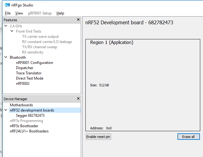
GND =>GNDyou can erase the protection using nRFgo Studio
- On the left, you can find a header named Segger, click on that.
- then it shows that it is locked, and you can click recover.
- after that you can erase it
- upload a new sketch using an ST-link V2 or the DK while you are still at it.
-
This looks like an Arduino-nano/pro-mini style device with an NRF51:
@alowhum said in nRF5 action!:
This looks like an Arduino-nano/pro-mini style device with an NRF51:
I tried uploading a simple blink sketch today. I found some code on github which suggested pin 23 and 24 are LED pins.
I got an error uploading via STM32 though.
debug_level: 2
0x4000
Info : The selected transport took over low-level target control. The results might differ compared to plain JTAG/SWD
adapter speed: 10000 kHz
Info : Unable to match requested speed 10000 kHz, using 4000 kHz
Info : Unable to match requested speed 10000 kHz, using 4000 kHz
Info : clock speed 4000 kHz
Info : STLINK v2 JTAG v17 API v2 SWIM v4 VID 0x0483 PID 0x3748
Info : using stlink api v2
Info : Target voltage: 3.233552
Warn : UNEXPECTED idcode: 0x0bb11477
Error: expected 1 of 1: 0x2ba01477
in procedure 'program'
in procedure 'init' called at file "embedded:startup.tcl", line 473
in procedure 'ocd_bouncer'
** OpenOCD init failed **
shutdown command invoked -
@maciekczwa said in nRF5 action!:
Licensed under GNU GPL v2
For bug reports, read
http://openocd.org/doc/doxygen/bugs.html
debug_level: 2
0x4000
Info : The selected transport took over low-level target control. The results might differ compared to plain JTAG/SWD
adapter speed: 10000 kHz
Info : Unable to match requested speed 10000 kHz, using 4000 kHz
Info : Unable to match requested speed 10000 kHz, using 4000 kHz
Info : clock speed 4000 kHz
Info : STLINK v2 JTAG v17 API v2 SWIM v4 VID 0x0483 PID 0x3748
Info : using stlink api v2
Info : Target voltage: 3.241270
Info : nrf52.cpu: hardware has 0 breakpoints, 2 watchpoints
Error: timed out while waiting for target halted
TARGET: nrf52.cpu - Not halted
in procedure 'program'
in procedure 'reset' called at file "embedded:startup.tcl", line 478
in procedure 'ocd_bouncer'**embedded:startup.tcl:454: Error: ** Unable to reset target ****
in procedure 'program'
in procedure 'program_error' called at file "embedded:startup.tcl", line 479
at file "embedded:startup.tcl", line 454
wybrany port szeregowy at file "embedded:startup.tcl", line 454maybe someone else already found the solution, but it took me a while to figure it out for myself.
So for documentation sake:
Just had the exact same things with new Ebyte NRF52832 modules, ST-Link v2 couldn't erase it. (the old once did erase without a single problem )
After some digging, I found the following:
(I'm using my NRF52832-DK for it, maybe other devices work as well, just tested this one)DK => Ebyte module
GND(detect) => GND
SWDIO => SWDIO
SWDCLK => SWCLK
VTG => 3,3V
3,3V => 3,3V
GND =>GNDyou can erase the protection using nRFgo Studio
- On the left, you can find a header named Segger, click on that.
- then it shows that it is locked, and you can click recover.
- after that you can erase it
- upload a new sketch using an ST-link V2 or the DK while you are still at it.
-
@toyman yup, I tried that one, but all it kept saying was something like; can't find programmer.. and this method, which has a GUI, worked without incident :)
@omemanti that's strange, I use the methos regularly and it worls fine.
Oh! Actually, sandeep's installation messes up Jlink drivers so they require reinstall for the method to work.
That's why I am using arduino nrf5 with BMP to completely separate Arduino from Jlink -
FYI, I'm switching from uPython over to uLisp. It already worked on the BBC:microbit, and I just now got uLisp working on the nRF52832. Because uLisp relies on Sandeep's library, it doesn't yet support the nRF52840. However, if/when Sandeep's library does support the nRF52840, the uLisp upgrade will be fairly easy.
-
FYI, I'm switching from uPython over to uLisp. It already worked on the BBC:microbit, and I just now got uLisp working on the nRF52832. Because uLisp relies on Sandeep's library, it doesn't yet support the nRF52840. However, if/when Sandeep's library does support the nRF52840, the uLisp upgrade will be fairly easy.
@neverdie said in nRF5 action!:
FYI, I'm switching from uPython over to uLisp.
What is the reason for this switch ?
-
@neverdie said in nRF5 action!:
FYI, I'm switching from uPython over to uLisp.
What is the reason for this switch ?
- uPython seemed to require an intimate understanding of a rather complicated build process. I kept running into build-related snags. Maybe in the future they will simplify it.
- Its garbage collector can't handle heap fragmentation, and it appears that it never will.
- Adding c-extensions is a rather arcane process.
In contrast, the uLisp build process is far simpler, and uLisp appears to have a proper garbage collector. Adding c-extensions is relatively easy.
-
For anyone interested, I posted a simple nRF52 Tx and Rx demo program written in Forth: https://github.com/rabbithat/nRF52_SimpleTxRxDemo
This code is a good starting point for beginners, because it is already working. You can easily modify the code to do whatever transmitting and receiving you want.
-
I just now posted a wireless Forth REPL for nRF52's on github:
https://github.com/rabbithat/nRF52_wireless_Forth_REPLThis allows you to wirelessly connect with a nRF52 remote node to update and/or interact with your code exactly the same as if the remote node was directly connected to your computer.
:grinning: :grinning: :grinning: -
I have recently installed an Ebyte E73 as my gateway with a DHT22. The problem is that I need to restart the gateway every 2 days and I can't figure out why. Can someone help me?
/** The MySensors Arduino library handles the wireless radio link and protocol between your home built sensors/actuators and HA controller of choice. The sensors forms a self healing radio network with optional repeaters. Each repeater and gateway builds a routing tables in EEPROM which keeps track of the network topology allowing messages to be routed to nodes. Created by Henrik Ekblad <henrik.ekblad@mysensors.org> Copyright (C) 2013-2017 Sensnology AB Full contributor list: https://github.com/mysensors/Arduino/graphs/contributors Documentation: http://www.mysensors.org Support Forum: http://forum.mysensors.org This program is free software; you can redistribute it and/or modify it under the terms of the GNU General Public License version 2 as published by the Free Software Foundation. ******************************* REVISION HISTORY */ // Enable debug prints #define MY_DEBUG // Enable serial gateway #define MY_GATEWAY_SERIAL // Set blinking period #define MY_DEFAULT_LED_BLINK_PERIOD 300 // Enable and select radio type attached //#define MY_RADIO_NRF24 #define MY_RADIO_NRF5_ESB //#define MY_RADIO_RFM69 //#define MY_RADIO_RFM95 #include <SPI.h> #include <MySensors.h> #include "DHT.h" int switch_led = 1; #define ledPin 11 // Set this to the pin you connected the DHT's data pin to #define DHT_DATA_PIN 02 #define DHTTYPE DHT22 // DHT 22 (AM2302), AM2321 // Set this offset if the sensor has a permanent small offset to the real temperatures. // In Celsius degrees (as measured by the device) #define SENSOR_TEMP_OFFSET 0 // Sleep time between sensor updates (in milliseconds) // Must be >1000ms for DHT22 and >2000ms for DHT11 static const uint64_t UPDATE_INTERVAL = 600000; // Force sending an update of the temperature after n sensor reads, so a controller showing the // timestamp of the last update doesn't show something like 3 hours in the unlikely case, that // the value didn't change since; // i.e. the sensor would force sending an update every UPDATE_INTERVAL*FORCE_UPDATE_N_READS [ms] static const uint8_t FORCE_UPDATE_N_READS = 10; #define CHILD_ID_HUM 1 #define CHILD_ID_TEMP 0 float lastTemp; float lastHum; uint8_t nNoUpdatesTemp; uint8_t nNoUpdatesHum; bool metric = true; MyMessage msgHum(CHILD_ID_HUM, V_HUM); MyMessage msgTemp(CHILD_ID_TEMP, V_TEMP); DHT dht(DHT_DATA_PIN, DHTTYPE); void setup() { hwPinMode(LED_BUILTIN,OUTPUT_D0H1); NRF_CLOCK->INTENSET=B11; //enable interrupts for EVENTS_HFCLKSTARTED and EVENTS_LFCLKSTARTED NRF_CLOCK->TASKS_HFCLKSTART=1; //start the high frequency crystal oscillator clock while (!(NRF_CLOCK->EVENTS_HFCLKSTARTED)) {} //wait until high frequency crystal oscillator clock is up to speed and working pinMode(PIN_LED1, OUTPUT); digitalWrite(PIN_LED1, HIGH); dht.begin(); // set data pin of DHT sensor } void presentation() { // Send the sketch version information to the gateway and controller sendSketchInfo("Serial Gateway nrf52", "1.0"); wait(500); // Register all sensors to gw (they will be created as child devices) present(CHILD_ID_TEMP, S_TEMP); present(CHILD_ID_HUM, S_HUM); } void loop() { // Reading temperature or humidity takes about 250 milliseconds! // Sensor readings may also be up to 2 seconds 'old' (its a very slow sensor) float h = dht.readHumidity(); // Read temperature as Celsius (the default) float t = dht.readTemperature(); // Read temperature as Fahrenheit (isFahrenheit = true) float f = dht.readTemperature(true); Serial.print("Test print"); // Check if any reads failed and exit early (to try again). if (isnan(h) || isnan(t) || isnan(f)) { //Serial.println("Failed to read from DHT sensor!"); return; } else { send(msgHum.set(h, 1)); send(msgTemp.set(t, 1)); } wait(UPDATE_INTERVAL); } -
Hi every one. I'm very new in mysensors (I use bad English)
in my sketch how to setup sleep,interrupt for 3 button (์NRF51822)
thank you#define MY_DEBUG #define MY_NODE_ID 4 //#define MY_RADIO_NRF24 #define MY_RADIO_NRF5_ESB #include <SPI.h> #include <MySensors.h> #define CHILD_ID_SW1 1 #define CHILD_ID_SW2 2 #define CHILD_ID_SW3 3 #define BUTTON1_PIN 3 #define BUTTON2_PIN 4 #define BUTTON3_PIN 5 boolean sw1State; boolean lastState1; boolean tripped1 = HIGH; boolean sw2State; boolean lastState2; boolean tripped2 = HIGH; boolean sw3State; boolean lastState3; boolean tripped3 = HIGH; MyMessage msg1(CHILD_ID_SW1, V_TRIPPED); MyMessage msg2(CHILD_ID_SW2, V_TRIPPED); MyMessage msg3(CHILD_ID_SW3, V_TRIPPED); void presentation() { sendSketchInfo("Push Button 1", "1.0"); present(CHILD_ID_SW1, S_DOOR); present(CHILD_ID_SW2, S_DOOR); present(CHILD_ID_SW3, S_DOOR); } void setup() { pinMode (BUTTON1_PIN,INPUT_PULLUP); pinMode (BUTTON2_PIN,INPUT_PULLUP); pinMode (BUTTON3_PIN,INPUT_PULLUP); } void loop() { sw1State = digitalRead(BUTTON1_PIN); if ( ( sw1State == LOW) && (lastState1 == HIGH) ) tripped1 = !tripped1; send(msg1.set(tripped1==HIGH ? "1" : "0")); lastState1 = sw1State; sw2State = digitalRead(BUTTON2_PIN); if ( ( sw2State == LOW) && (lastState2 == HIGH) ) tripped2 = !tripped2; send(msg2.set(tripped2==HIGH ? "1" : "0")); lastState2 = sw2State; sw3State = digitalRead(BUTTON3_PIN); if ( ( sw3State == LOW) && (lastState3 == HIGH) ) tripped3 = !tripped3; send(msg3.set(tripped3==HIGH ? "1" : "0")); lastState3 = sw3State; //sleep(digitalPinToInterrupt(BUTTON1_PIN), CHANGE, 0); //sleep(INTERRUPT, CHANGE, 0); } -
I have recently installed an Ebyte E73 as my gateway with a DHT22. The problem is that I need to restart the gateway every 2 days and I can't figure out why. Can someone help me?
/** The MySensors Arduino library handles the wireless radio link and protocol between your home built sensors/actuators and HA controller of choice. The sensors forms a self healing radio network with optional repeaters. Each repeater and gateway builds a routing tables in EEPROM which keeps track of the network topology allowing messages to be routed to nodes. Created by Henrik Ekblad <henrik.ekblad@mysensors.org> Copyright (C) 2013-2017 Sensnology AB Full contributor list: https://github.com/mysensors/Arduino/graphs/contributors Documentation: http://www.mysensors.org Support Forum: http://forum.mysensors.org This program is free software; you can redistribute it and/or modify it under the terms of the GNU General Public License version 2 as published by the Free Software Foundation. ******************************* REVISION HISTORY */ // Enable debug prints #define MY_DEBUG // Enable serial gateway #define MY_GATEWAY_SERIAL // Set blinking period #define MY_DEFAULT_LED_BLINK_PERIOD 300 // Enable and select radio type attached //#define MY_RADIO_NRF24 #define MY_RADIO_NRF5_ESB //#define MY_RADIO_RFM69 //#define MY_RADIO_RFM95 #include <SPI.h> #include <MySensors.h> #include "DHT.h" int switch_led = 1; #define ledPin 11 // Set this to the pin you connected the DHT's data pin to #define DHT_DATA_PIN 02 #define DHTTYPE DHT22 // DHT 22 (AM2302), AM2321 // Set this offset if the sensor has a permanent small offset to the real temperatures. // In Celsius degrees (as measured by the device) #define SENSOR_TEMP_OFFSET 0 // Sleep time between sensor updates (in milliseconds) // Must be >1000ms for DHT22 and >2000ms for DHT11 static const uint64_t UPDATE_INTERVAL = 600000; // Force sending an update of the temperature after n sensor reads, so a controller showing the // timestamp of the last update doesn't show something like 3 hours in the unlikely case, that // the value didn't change since; // i.e. the sensor would force sending an update every UPDATE_INTERVAL*FORCE_UPDATE_N_READS [ms] static const uint8_t FORCE_UPDATE_N_READS = 10; #define CHILD_ID_HUM 1 #define CHILD_ID_TEMP 0 float lastTemp; float lastHum; uint8_t nNoUpdatesTemp; uint8_t nNoUpdatesHum; bool metric = true; MyMessage msgHum(CHILD_ID_HUM, V_HUM); MyMessage msgTemp(CHILD_ID_TEMP, V_TEMP); DHT dht(DHT_DATA_PIN, DHTTYPE); void setup() { hwPinMode(LED_BUILTIN,OUTPUT_D0H1); NRF_CLOCK->INTENSET=B11; //enable interrupts for EVENTS_HFCLKSTARTED and EVENTS_LFCLKSTARTED NRF_CLOCK->TASKS_HFCLKSTART=1; //start the high frequency crystal oscillator clock while (!(NRF_CLOCK->EVENTS_HFCLKSTARTED)) {} //wait until high frequency crystal oscillator clock is up to speed and working pinMode(PIN_LED1, OUTPUT); digitalWrite(PIN_LED1, HIGH); dht.begin(); // set data pin of DHT sensor } void presentation() { // Send the sketch version information to the gateway and controller sendSketchInfo("Serial Gateway nrf52", "1.0"); wait(500); // Register all sensors to gw (they will be created as child devices) present(CHILD_ID_TEMP, S_TEMP); present(CHILD_ID_HUM, S_HUM); } void loop() { // Reading temperature or humidity takes about 250 milliseconds! // Sensor readings may also be up to 2 seconds 'old' (its a very slow sensor) float h = dht.readHumidity(); // Read temperature as Celsius (the default) float t = dht.readTemperature(); // Read temperature as Fahrenheit (isFahrenheit = true) float f = dht.readTemperature(true); Serial.print("Test print"); // Check if any reads failed and exit early (to try again). if (isnan(h) || isnan(t) || isnan(f)) { //Serial.println("Failed to read from DHT sensor!"); return; } else { send(msgHum.set(h, 1)); send(msgTemp.set(t, 1)); } wait(UPDATE_INTERVAL); }@smilvert do you have some more information? like some serial output?
I had some issues with statements that uses millis(), in about 1,5 up to 2 days (much shorter the normaly I suppose) it did its rollover back to 0. This messed some waiting times for me.
-
Hi every one. I'm very new in mysensors (I use bad English)
in my sketch how to setup sleep,interrupt for 3 button (์NRF51822)
thank you#define MY_DEBUG #define MY_NODE_ID 4 //#define MY_RADIO_NRF24 #define MY_RADIO_NRF5_ESB #include <SPI.h> #include <MySensors.h> #define CHILD_ID_SW1 1 #define CHILD_ID_SW2 2 #define CHILD_ID_SW3 3 #define BUTTON1_PIN 3 #define BUTTON2_PIN 4 #define BUTTON3_PIN 5 boolean sw1State; boolean lastState1; boolean tripped1 = HIGH; boolean sw2State; boolean lastState2; boolean tripped2 = HIGH; boolean sw3State; boolean lastState3; boolean tripped3 = HIGH; MyMessage msg1(CHILD_ID_SW1, V_TRIPPED); MyMessage msg2(CHILD_ID_SW2, V_TRIPPED); MyMessage msg3(CHILD_ID_SW3, V_TRIPPED); void presentation() { sendSketchInfo("Push Button 1", "1.0"); present(CHILD_ID_SW1, S_DOOR); present(CHILD_ID_SW2, S_DOOR); present(CHILD_ID_SW3, S_DOOR); } void setup() { pinMode (BUTTON1_PIN,INPUT_PULLUP); pinMode (BUTTON2_PIN,INPUT_PULLUP); pinMode (BUTTON3_PIN,INPUT_PULLUP); } void loop() { sw1State = digitalRead(BUTTON1_PIN); if ( ( sw1State == LOW) && (lastState1 == HIGH) ) tripped1 = !tripped1; send(msg1.set(tripped1==HIGH ? "1" : "0")); lastState1 = sw1State; sw2State = digitalRead(BUTTON2_PIN); if ( ( sw2State == LOW) && (lastState2 == HIGH) ) tripped2 = !tripped2; send(msg2.set(tripped2==HIGH ? "1" : "0")); lastState2 = sw2State; sw3State = digitalRead(BUTTON3_PIN); if ( ( sw3State == LOW) && (lastState3 == HIGH) ) tripped3 = !tripped3; send(msg3.set(tripped3==HIGH ? "1" : "0")); lastState3 = sw3State; //sleep(digitalPinToInterrupt(BUTTON1_PIN), CHANGE, 0); //sleep(INTERRUPT, CHANGE, 0); }@magkudjee
MySensors will support 2 interrupts using sleep. I do not think it will support 3.
Use this format for the sleep call:
sleep(interrupt1, mode1, interrupt2, mode2, ms=0);
In your case: sleep(BUTTON1_PIN, CHANGE, BUTTON2_PIN, CHANGE, 0);I don't know how to handle the 3rd interrupt.
Check the MySensors API document here: https://www.mysensors.org/download/sensor_api_20#sleeping