Cant even get my first node working...
-
Controller is OpenHABian on Rpi3
Gateway is Arduino Mega w/ W5100 Shield & NRF24l01
Node is Arduino Nano w/ NRF24l01As far as I am aware, the gateway is working fine, running the Gateway5100mqtt example I can send and receive messages through MQTT, tested inside Pi terminal.
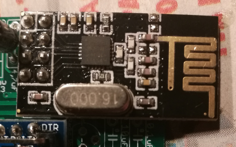
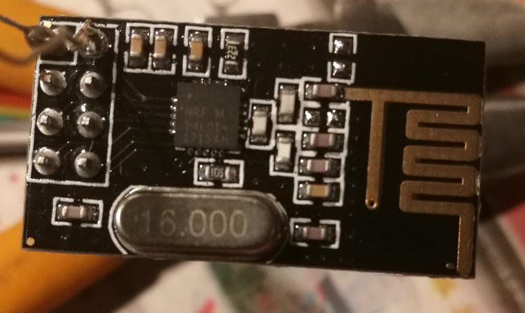
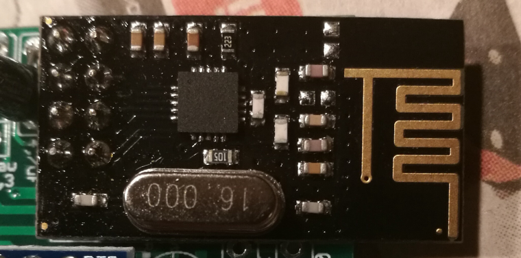
BUT, my node just wont work, I've tried two different NRF modules, both work on the gateway, I've tested all the pins on the nano with an led and they are working.
Running the Temp/Humidity example on the nano this is the error I am getting:
0 MCO:BGN:INIT NODE,CP=RNNNA--,VER=2.1.1
3 TSM:INIT
4 TSF:WUR:MS=0
11 !TSM:INIT:TSP FAIL
12 TSM:FAIL:CNT=1
14 TSM:FAIL:PDT
10016 TSM:FAIL:RE-INIT
10018 TSM:INIT
10024 !TSM:INIT:TSP FAILI have also tried clearing EEPROM with that sketch.
Please any help at all, this is driving me insane!
update: have also tried in an arduino uno now with the same error
-
No one knows how to fix this? I'm using known working components, I've followed the getting started guide, beginning to feel like mysensors is alot more trouble than its worth...
@AndyRoo - Hi!
It seems like the radio cant be initialised.
You should re-check all your wirings and power to the radio. -
@AndyRoo - Hi!
It seems like the radio cant be initialised.
You should re-check all your wirings and power to the radio.@sundberg84 Hi,
Thanks for your reply, unless the wiring on the website is wrong, then everything is correct, I've tripled checked.
Could you confirm the wiring for a nano and uno are the same and if what's on the website matches what you are using?
-
@sundberg84 Hi,
Thanks for your reply, unless the wiring on the website is wrong, then everything is correct, I've tripled checked.
Could you confirm the wiring for a nano and uno are the same and if what's on the website matches what you are using?
-
Try swapping radios between the gateway and node just to make sure radio is not fried. It could be a wiring problem like said before or a power problem.
-
Any solution to this? I have the same problem atm. Tried 3 or 4 different nrf24l01+ but with the same failures. I'm suspecting it's related to my sketches or something. Can't wire that many radios wrong, and they are from different vendors. My gateway is an Uno running with an W5100 and latest MySensors dev. Seems to be connecting just fine to both my Vera and when I tried it in Domoticz. The GW debug shows no fails.
-
try with just some example sketches to see if the radios are correctly communicating. Did you put a capacitor on the radio module?
@gohan I made a serial gateway with an Nano+Nrf24L01+ and hooked it up to my computer. Just to bypass the possibility that my regular gateway have radio problems. But even with that simple setup I get "11 !TSM:INIT:TSP FAIL" from the Nano. I have tried with 4.7, 47 and 100uF on the radio.
-
-
Im banging my head against the wall here. Uninstalled IDE and reinstalled version 1.6.4 and added Mysensors lib from the menus. Uploaded the GatewaySerial to a new Uno with attached radio+cap. No luck.
Uninstalled IDE and installed latest version which has Mysensors preinstalled. Same sketch. No luck. Gonna try with yet another radio. But I cant see how the 3 i've already tried could be broken.
-
@gohan http://www.ebay.com/itm/400594940658?rmvSB=true
Its the radios linked in mysensors store...https://www.m.nu/breakout-boards/nrf24l01
"swedish" one. -
@gohan http://www.ebay.com/itm/400594940658?rmvSB=true
Its the radios linked in mysensors store...https://www.m.nu/breakout-boards/nrf24l01
"swedish" one. -
@gohan http://www.ebay.com/itm/400594940658?rmvSB=true
Its the radios linked in mysensors store...https://www.m.nu/breakout-boards/nrf24l01
"swedish" one.@royson84 - do yo have a multimeter and can comfirm there are power to the radio? If you are using the PCB you need to have atleast one jumper connected (as we spoke about - so I suspect that is ok). Could you post a picture of the complete setup?
I live pretty near you (1.5h) in worst case scenario ;)


