RFM69 ATC not working?
-
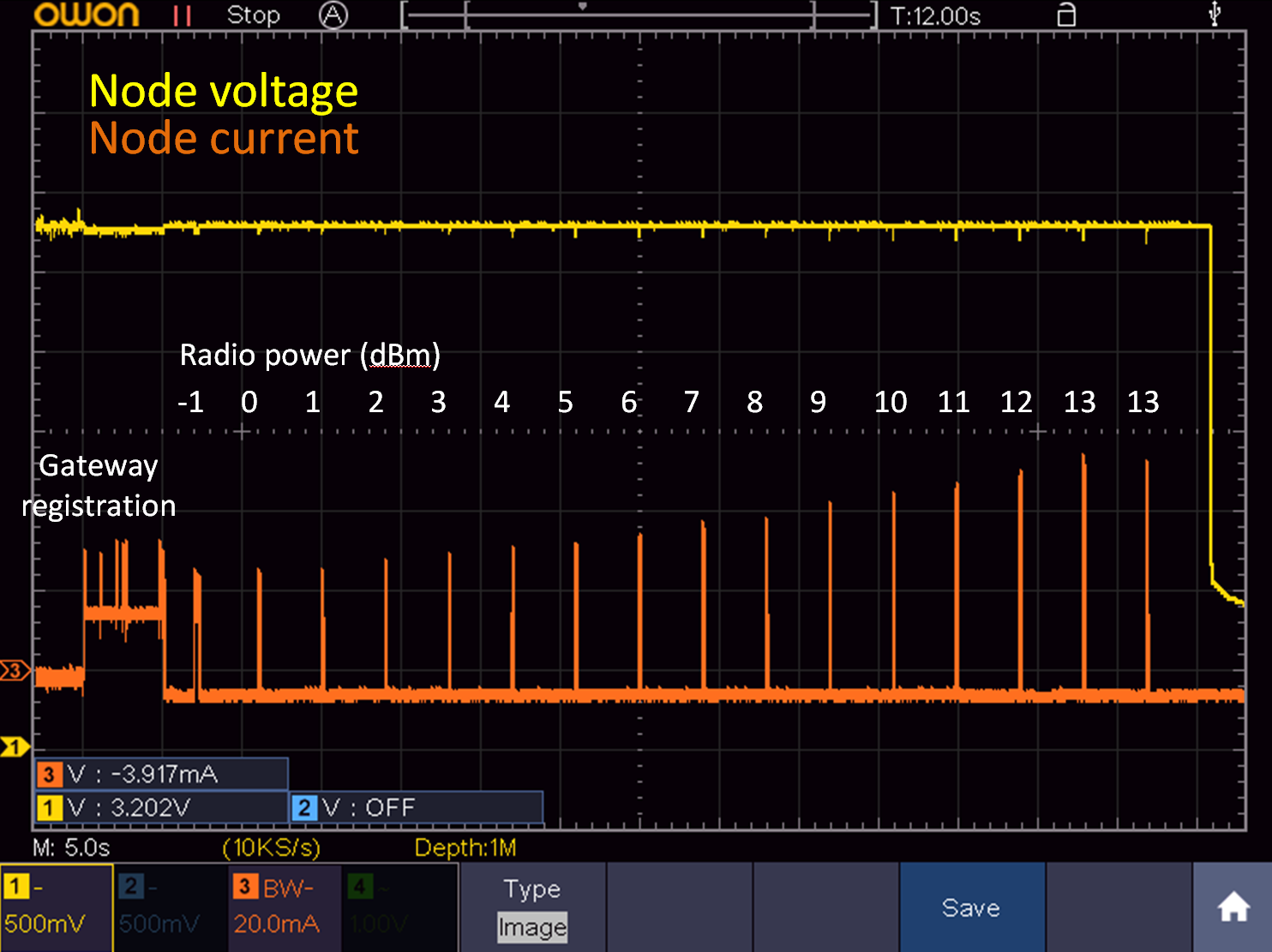
I want to use my MySensors/RFM69HW node with the lowest power possible. However, with ATC enabled, I noticed that the power is always adjusted to the maximum level possible. To investigate, I did an experiment in which I disabled ATC and increased the radio power from -2dBm to 13dBm and have the node send the receiving RSSI and sending RSSI. I recorded both the node voltage and current, as shown in the image below.
It is clear that the radio power is linearly increased, which is good. However, the reported receiving/sending RSSIs do not change, as shown by the following gateway log (format: TX power, receiving RSSI, sending RSSI):
TSF:MSG:READ,12-12-0,s=3,c=1,t=24,pt=7,l=5,sg=0:-2.00
TSF:MSG:READ,12-12-0,s=3,c=1,t=24,pt=7,l=5,sg=0:-98.000
TSF:MSG:READ,12-12-0,s=3,c=1,t=24,pt=7,l=5,sg=0:-66.000

TSF:MSG:READ,12-12-0,s=3,c=1,t=24,pt=7,l=5,sg=0:-1.00
TSF:MSG:READ,12-12-0,s=3,c=1,t=24,pt=7,l=5,sg=0:-96.000
TSF:MSG:READ,12-12-0,s=3,c=1,t=24,pt=7,l=5,sg=0:-67.000

TSF:MSG:READ,12-12-0,s=3,c=1,t=24,pt=7,l=5,sg=0:0.00
TSF:MSG:READ,12-12-0,s=3,c=1,t=24,pt=7,l=5,sg=0:-99.000
TSF:MSG:READ,12-12-0,s=3,c=1,t=24,pt=7,l=5,sg=0:-66.000

TSF:MSG:READ,12-12-0,s=3,c=1,t=24,pt=7,l=5,sg=0:1.00
TSF:MSG:READ,12-12-0,s=3,c=1,t=24,pt=7,l=5,sg=0:-102.000
TSF:MSG:READ,12-12-0,s=3,c=1,t=24,pt=7,l=5,sg=0:-64.000

TSF:MSG:READ,12-12-0,s=3,c=1,t=24,pt=7,l=5,sg=0:2.00
TSF:MSG:READ,12-12-0,s=3,c=1,t=24,pt=7,l=5,sg=0:-100.000
TSF:MSG:READ,12-12-0,s=3,c=1,t=24,pt=7,l=5,sg=0:-62.000

TSF:MSG:READ,12-12-0,s=3,c=1,t=24,pt=7,l=5,sg=0:3.00
TSF:MSG:READ,12-12-0,s=3,c=1,t=24,pt=7,l=5,sg=0:-96.000
TSF:MSG:READ,12-12-0,s=3,c=1,t=24,pt=7,l=5,sg=0:-61.000

TSF:MSG:READ,12-12-0,s=3,c=1,t=24,pt=7,l=5,sg=0:4.00
TSF:MSG:READ,12-12-0,s=3,c=1,t=24,pt=7,l=5,sg=0:-100.000
TSF:MSG:READ,12-12-0,s=3,c=1,t=24,pt=7,l=5,sg=0:-61.000

TSF:MSG:READ,12-12-0,s=3,c=1,t=24,pt=7,l=5,sg=0:5.00
TSF:MSG:READ,12-12-0,s=3,c=1,t=24,pt=7,l=5,sg=0:-96.000
TSF:MSG:READ,12-12-0,s=3,c=1,t=24,pt=7,l=5,sg=0:-60.000

TSF:MSG:READ,12-12-0,s=3,c=1,t=24,pt=7,l=5,sg=0:6.00
TSF:MSG:READ,12-12-0,s=3,c=1,t=24,pt=7,l=5,sg=0:-92.000
TSF:MSG:READ,12-12-0,s=3,c=1,t=24,pt=7,l=5,sg=0:-60.000

TSF:MSG:READ,12-12-0,s=3,c=1,t=24,pt=7,l=5,sg=0:7.00
TSF:MSG:READ,12-12-0,s=3,c=1,t=24,pt=7,l=5,sg=0:-97.000
TSF:MSG:READ,12-12-0,s=3,c=1,t=24,pt=7,l=5,sg=0:-59.000

TSF:MSG:READ,12-12-0,s=3,c=1,t=24,pt=7,l=5,sg=0:8.00
TSF:MSG:READ,12-12-0,s=3,c=1,t=24,pt=7,l=5,sg=0:-97.000
TSF:MSG:READ,12-12-0,s=3,c=1,t=24,pt=7,l=5,sg=0:-66.000

TSF:MSG:READ,12-12-0,s=3,c=1,t=24,pt=7,l=5,sg=0:9.00
TSF:MSG:READ,12-12-0,s=3,c=1,t=24,pt=7,l=5,sg=0:-100.000
TSF:MSG:READ,12-12-0,s=3,c=1,t=24,pt=7,l=5,sg=0:-60.000

TSF:MSG:READ,12-12-0,s=3,c=1,t=24,pt=7,l=5,sg=0:10.00
TSF:MSG:READ,12-12-0,s=3,c=1,t=24,pt=7,l=5,sg=0:-97.000
TSF:MSG:READ,12-12-0,s=3,c=1,t=24,pt=7,l=5,sg=0:-59.000

TSF:MSG:READ,12-12-0,s=3,c=1,t=24,pt=7,l=5,sg=0:11.00
TSF:MSG:READ,12-12-0,s=3,c=1,t=24,pt=7,l=5,sg=0:-100.000
TSF:MSG:READ,12-12-0,s=3,c=1,t=24,pt=7,l=5,sg=0:-64.000

TSF:MSG:READ,12-12-0,s=3,c=1,t=24,pt=7,l=5,sg=0:12.00
TSF:MSG:READ,12-12-0,s=3,c=1,t=24,pt=7,l=5,sg=0:-102.000
TSF:MSG:READ,12-12-0,s=3,c=1,t=24,pt=7,l=5,sg=0:-58.000

TSF:MSG:READ,12-12-0,s=3,c=1,t=24,pt=7,l=5,sg=0:13.00
TSF:MSG:READ,12-12-0,s=3,c=1,t=24,pt=7,l=5,sg=0:-100.000
TSF:MSG:READ,12-12-0,s=3,c=1,t=24,pt=7,l=5,sg=0:-66.000
The receiving RSSI is always about -100dBm and the sending RSSI is always around -60/-70 dBm.
The RFM69HW has a 22uF ceramic capacitor and a 480uF elcap to decouple its power supply.
I used MySensors 2.2.0 for this measurement, but I get the same result with 2.3.0.
Does anyone have a clue what may be causing the RSSI to be independent of the transmit power?
-
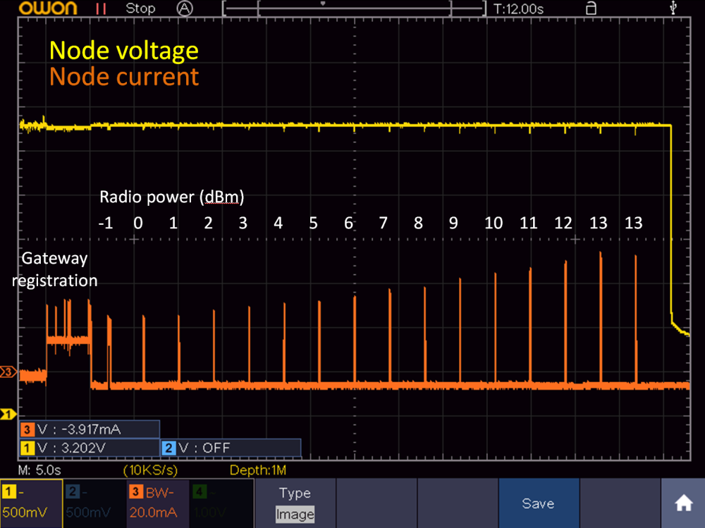
I want to use my MySensors/RFM69HW node with the lowest power possible. However, with ATC enabled, I noticed that the power is always adjusted to the maximum level possible. To investigate, I did an experiment in which I disabled ATC and increased the radio power from -2dBm to 13dBm and have the node send the receiving RSSI and sending RSSI. I recorded both the node voltage and current, as shown in the image below.
It is clear that the radio power is linearly increased, which is good. However, the reported receiving/sending RSSIs do not change, as shown by the following gateway log (format: TX power, receiving RSSI, sending RSSI):
TSF:MSG:READ,12-12-0,s=3,c=1,t=24,pt=7,l=5,sg=0:-2.00
TSF:MSG:READ,12-12-0,s=3,c=1,t=24,pt=7,l=5,sg=0:-98.000
TSF:MSG:READ,12-12-0,s=3,c=1,t=24,pt=7,l=5,sg=0:-66.000

TSF:MSG:READ,12-12-0,s=3,c=1,t=24,pt=7,l=5,sg=0:-1.00
TSF:MSG:READ,12-12-0,s=3,c=1,t=24,pt=7,l=5,sg=0:-96.000
TSF:MSG:READ,12-12-0,s=3,c=1,t=24,pt=7,l=5,sg=0:-67.000

TSF:MSG:READ,12-12-0,s=3,c=1,t=24,pt=7,l=5,sg=0:0.00
TSF:MSG:READ,12-12-0,s=3,c=1,t=24,pt=7,l=5,sg=0:-99.000
TSF:MSG:READ,12-12-0,s=3,c=1,t=24,pt=7,l=5,sg=0:-66.000

TSF:MSG:READ,12-12-0,s=3,c=1,t=24,pt=7,l=5,sg=0:1.00
TSF:MSG:READ,12-12-0,s=3,c=1,t=24,pt=7,l=5,sg=0:-102.000
TSF:MSG:READ,12-12-0,s=3,c=1,t=24,pt=7,l=5,sg=0:-64.000

TSF:MSG:READ,12-12-0,s=3,c=1,t=24,pt=7,l=5,sg=0:2.00
TSF:MSG:READ,12-12-0,s=3,c=1,t=24,pt=7,l=5,sg=0:-100.000
TSF:MSG:READ,12-12-0,s=3,c=1,t=24,pt=7,l=5,sg=0:-62.000

TSF:MSG:READ,12-12-0,s=3,c=1,t=24,pt=7,l=5,sg=0:3.00
TSF:MSG:READ,12-12-0,s=3,c=1,t=24,pt=7,l=5,sg=0:-96.000
TSF:MSG:READ,12-12-0,s=3,c=1,t=24,pt=7,l=5,sg=0:-61.000

TSF:MSG:READ,12-12-0,s=3,c=1,t=24,pt=7,l=5,sg=0:4.00
TSF:MSG:READ,12-12-0,s=3,c=1,t=24,pt=7,l=5,sg=0:-100.000
TSF:MSG:READ,12-12-0,s=3,c=1,t=24,pt=7,l=5,sg=0:-61.000

TSF:MSG:READ,12-12-0,s=3,c=1,t=24,pt=7,l=5,sg=0:5.00
TSF:MSG:READ,12-12-0,s=3,c=1,t=24,pt=7,l=5,sg=0:-96.000
TSF:MSG:READ,12-12-0,s=3,c=1,t=24,pt=7,l=5,sg=0:-60.000

TSF:MSG:READ,12-12-0,s=3,c=1,t=24,pt=7,l=5,sg=0:6.00
TSF:MSG:READ,12-12-0,s=3,c=1,t=24,pt=7,l=5,sg=0:-92.000
TSF:MSG:READ,12-12-0,s=3,c=1,t=24,pt=7,l=5,sg=0:-60.000

TSF:MSG:READ,12-12-0,s=3,c=1,t=24,pt=7,l=5,sg=0:7.00
TSF:MSG:READ,12-12-0,s=3,c=1,t=24,pt=7,l=5,sg=0:-97.000
TSF:MSG:READ,12-12-0,s=3,c=1,t=24,pt=7,l=5,sg=0:-59.000

TSF:MSG:READ,12-12-0,s=3,c=1,t=24,pt=7,l=5,sg=0:8.00
TSF:MSG:READ,12-12-0,s=3,c=1,t=24,pt=7,l=5,sg=0:-97.000
TSF:MSG:READ,12-12-0,s=3,c=1,t=24,pt=7,l=5,sg=0:-66.000

TSF:MSG:READ,12-12-0,s=3,c=1,t=24,pt=7,l=5,sg=0:9.00
TSF:MSG:READ,12-12-0,s=3,c=1,t=24,pt=7,l=5,sg=0:-100.000
TSF:MSG:READ,12-12-0,s=3,c=1,t=24,pt=7,l=5,sg=0:-60.000

TSF:MSG:READ,12-12-0,s=3,c=1,t=24,pt=7,l=5,sg=0:10.00
TSF:MSG:READ,12-12-0,s=3,c=1,t=24,pt=7,l=5,sg=0:-97.000
TSF:MSG:READ,12-12-0,s=3,c=1,t=24,pt=7,l=5,sg=0:-59.000

TSF:MSG:READ,12-12-0,s=3,c=1,t=24,pt=7,l=5,sg=0:11.00
TSF:MSG:READ,12-12-0,s=3,c=1,t=24,pt=7,l=5,sg=0:-100.000
TSF:MSG:READ,12-12-0,s=3,c=1,t=24,pt=7,l=5,sg=0:-64.000

TSF:MSG:READ,12-12-0,s=3,c=1,t=24,pt=7,l=5,sg=0:12.00
TSF:MSG:READ,12-12-0,s=3,c=1,t=24,pt=7,l=5,sg=0:-102.000
TSF:MSG:READ,12-12-0,s=3,c=1,t=24,pt=7,l=5,sg=0:-58.000

TSF:MSG:READ,12-12-0,s=3,c=1,t=24,pt=7,l=5,sg=0:13.00
TSF:MSG:READ,12-12-0,s=3,c=1,t=24,pt=7,l=5,sg=0:-100.000
TSF:MSG:READ,12-12-0,s=3,c=1,t=24,pt=7,l=5,sg=0:-66.000
The receiving RSSI is always about -100dBm and the sending RSSI is always around -60/-70 dBm.
The RFM69HW has a 22uF ceramic capacitor and a 480uF elcap to decouple its power supply.
I used MySensors 2.2.0 for this measurement, but I get the same result with 2.3.0.
Does anyone have a clue what may be causing the RSSI to be independent of the transmit power?
-
@tsd are these numbers from the node’s own point of view, or the gateway’s? When (in the send/receive cycle) where they taken? How du you measure sending rssi?
@mfalkvidd
These numbers are from the node point of view.In the main loop, there's a piece of code that contains the RSSI measurements:
RFM69_setTxPowerLevel(i);

txPower     = RFM69_getTxPowerLevel();
rssiReceive = RFM69_getReceivingRSSI();
rssiSend    = RFM69_getSendingRSSI();

send(msgRSSI.set(txPower,2));		// Send receiving RSSI
send(msgRSSI.set(rssiSend,3));		// Send sending RSSI
send(msgRSSI.set(rssiReceive,3));		// Send sending RSSI
Should I use these functions differently?
-
also, getReceivingRSSI will return the RSSI from the last received message. It shouldn't be affected by the TX power of the node, and it is probably only updated when a message is sent to the node.
@mfalkvidd
I added a sending a temperature measurement before RFM69_getReceivingRSSI and enabled ATC, but get a similar result. The code is now as follows (I cleaned up the comments):txPower = RFM69_getTxPowerLevel(); // Get TX power float temperature = readTemp705x(); // Read temperature send(msgTemp.set(temperature, 1),0); // Send temperature rssiSend = RFM69_getSendingRSSI(); rssiReceive = RFM69_getReceivingRSSI(); send(msgRSSI.set(txPower,2)); // Send TX power send(msgRSSI.set(rssiSend,3)); // Send sending RSSI send(msgRSSI.set(rssiReceive,3)); // Send receiving RSSIThe gateway log shows that the power is increased until the maximum allowed (20 dBm), but no change in RSSI.
TSF:MSG:READ,12-12-0,s=1,c=1,t=0,pt=7,l=5,sg=0:23.8
TSF:MSG:READ,12-12-0,s=3,c=1,t=24,pt=7,l=5,sg=0:11.00
TSF:MSG:READ,12-12-0,s=3,c=1,t=24,pt=7,l=5,sg=0:-79.000
TSF:MSG:READ,12-12-0,s=3,c=1,t=24,pt=7,l=5,sg=0:-42.000

TSF:MSG:READ,12-12-0,s=1,c=1,t=0,pt=7,l=5,sg=0:23.8
TSF:MSG:READ,12-12-0,s=3,c=1,t=24,pt=7,l=5,sg=0:13.00
TSF:MSG:READ,12-12-0,s=3,c=1,t=24,pt=7,l=5,sg=0:-96.000
TSF:MSG:READ,12-12-0,s=3,c=1,t=24,pt=7,l=5,sg=0:-42.000

TSF:MSG:READ,12-12-0,s=1,c=1,t=0,pt=7,l=5,sg=0:23.8
TSF:MSG:READ,12-12-0,s=3,c=1,t=24,pt=7,l=5,sg=0:17.00
TSF:MSG:READ,12-12-0,s=3,c=1,t=24,pt=7,l=5,sg=0:-97.000
TSF:MSG:READ,12-12-0,s=3,c=1,t=24,pt=7,l=5,sg=0:-42.000

TSF:MSG:READ,12-12-0,s=1,c=1,t=0,pt=7,l=5,sg=0:23.8
TSF:MSG:READ,12-12-0,s=3,c=1,t=24,pt=7,l=5,sg=0:20.00
TSF:MSG:READ,12-12-0,s=3,c=1,t=24,pt=7,l=5,sg=0:-96.000
TSF:MSG:READ,12-12-0,s=3,c=1,t=24,pt=7,l=5,sg=0:-43.000
Any idea why this doesn't work?
I'm using a Raspberry Pi gateway now, is it easy to measure RSSI on that as well? I can switch to an Arduino gateway if required.
-
@tsd sorry, no idea at the moment.
For the rpi gw, just edit https://github.com/mysensors/MySensors/blob/development/examples_linux/mysgw.cpp (add the receive function from my sketch and start from the make step)
@mfalkvidd
OK, tnx for now. I'll look at gateway rssi tomorrow evening -
@tsd sorry, no idea at the moment.
For the rpi gw, just edit https://github.com/mysensors/MySensors/blob/development/examples_linux/mysgw.cpp (add the receive function from my sketch and start from the make step)
@mfalkvidd
I modified my code to include your receive function, but I wasn't sure how to use it in the main loop.#include <MySensors.h> MyMessage msgTemp(1,V_TEMP); MyMessage msgRSSI(2,V_LEVEL); #define ARDUINO 100 // This space is intended to be used to include arduino libraries #undef ARDUINO void setup() { // Setup locally attached sensors } void presentation() { // Present locally attached sensors here present(1,S_SOUND); } void loop() { // Send locally attached sensors data here receive(msgTemp); } void receive(const MyMessage &message) { int16_t rssiReceive = RFM69_getReceivingRSSI(); if (message.sender == 1 ) { send(msgRSSI.set(rssiReceive,0)); } }I figured that you have to use your receive function to capture a message from the node and then do an RSSI measurement. Since I have a msgTemp coming from the node, I used that.
After compiling the code and running the SGW, I get the following error in the logs:
Serial - write failed: Resource temporarily unavailableDo you know what I did wrong?
-
present(1,S_SOUND);should be
present(2,S_SOUND);and you don’t need MyMessage msgTemp(1,V_TEMP);
I am not sure about the error. Are you using the rpi gw as serial, mqtt or ethernet gw? (What was your configure command?)
@mfalkvidd
I improved the power supply of the RFM (added linear regulator) on the gateway and the error is gone.The code doesn't compile if I don't declare msgTemp, as I use msgTemp in the main loop.
Where should I see the message the GW is sending? On the node? I'm using a custom node without a serial connection, so I can't see incoming messages on the node. Is there a way to have the GW send the RSSI to its own log?
-
present(1,S_SOUND);should be
present(2,S_SOUND);and you don’t need MyMessage msgTemp(1,V_TEMP);
I am not sure about the error. Are you using the rpi gw as serial, mqtt or ethernet gw? (What was your configure command?)
@mfalkvidd
I was using serial gateway by the way. -
@mfalkvidd
I improved the power supply of the RFM (added linear regulator) on the gateway and the error is gone.The code doesn't compile if I don't declare msgTemp, as I use msgTemp in the main loop.
Where should I see the message the GW is sending? On the node? I'm using a custom node without a serial connection, so I can't see incoming messages on the node. Is there a way to have the GW send the RSSI to its own log?
-
@tsd I don’t know. I've always connected the gateways to my controller where I get logs and graphs.
Maybe you can use GATEWAY_DEBUG(text)
#define GATEWAY_DEBUG(text)or
#define MY_DEBUGdoesn't show any additional messages in the log, besides the node messages.
In the mean time I installed Domoticz to try it your way, but don't see the USB port that I tried to make by installing the serial gateway (ttyUSB020, which is not in /dev yet, so should be free).
This command should take care of that, right?
./configure --my-gateway=serial --my-serial-is-pty --my-serial-pty=/dev/ttyUSB020Sorry to be such a pain, but I would really like to get this sorted out.
-
#define GATEWAY_DEBUG(text)or
#define MY_DEBUGdoesn't show any additional messages in the log, besides the node messages.
In the mean time I installed Domoticz to try it your way, but don't see the USB port that I tried to make by installing the serial gateway (ttyUSB020, which is not in /dev yet, so should be free).
This command should take care of that, right?
./configure --my-gateway=serial --my-serial-is-pty --my-serial-pty=/dev/ttyUSB020Sorry to be such a pain, but I would really like to get this sorted out.
@tsd sorry for being unclear. This is how to use GATEWAY_DEBUG:
GATEWAY_DEBUG("This message will be sent to the debug log")But I am not sure it is available in sketches and I don't have access to a computer at the moment.
The configure command looks good. After running configure, did you continue with make, etc?
-
@tsd sorry for being unclear. This is how to use GATEWAY_DEBUG:
GATEWAY_DEBUG("This message will be sent to the debug log")But I am not sure it is available in sketches and I don't have access to a computer at the moment.
The configure command looks good. After running configure, did you continue with make, etc?
@mfalkvidd
Do you mean#define MY_DEBUG_VERBOSE_GATEWAYThat uses the GATEWAY_DEBUG("text") macro that you are referring to. I tried that, but it doesn't give any additional output in the log.
Yes, this is the complete code I run:
sudo ./configure --my-transport=rfm69 --my-rfm69-frequency=868 --my-is-rfm69hw --my-gateway=serial --my-serial-is-pty --my-serial-pty=/dev/ttyUSB020
sudo make install
sudo systemctl start mysgw.service
But ttyUSB020 doesn't appear in /dev afterwards, nor does Domoticz list it.
-
@mfalkvidd
Do you mean#define MY_DEBUG_VERBOSE_GATEWAYThat uses the GATEWAY_DEBUG("text") macro that you are referring to. I tried that, but it doesn't give any additional output in the log.
Yes, this is the complete code I run:
sudo ./configure --my-transport=rfm69 --my-rfm69-frequency=868 --my-is-rfm69hw --my-gateway=serial --my-serial-is-pty --my-serial-pty=/dev/ttyUSB020
sudo make install
sudo systemctl start mysgw.service
But ttyUSB020 doesn't appear in /dev afterwards, nor does Domoticz list it.
@tsd I think you'll need to run make before make install.
configure prepares the settings for make
make compiles the code into an executable file called mysgw, including changes to the cpp file and the settings from the configure command
make install copies the mysgw executable to /etc/init.d/ -
If I run "make install" while the code has not compiled yet, it will compile before installing. If you first run "make" seperately, "make install" will only install.
I'm almost there. I configured an Ethernet gateway (couldn't get serial gateway to work) and can now see the temperature, receive RSSI and sending RSSI from the node in Domoticz.
The gateway receive function shows up as "S_ARDUINO_REPEATER_NODE", but there's no data yet.
What data should I pass on to your receive function? My gateway code is now as follows:
#define MY_DEBUG_VERBOSE_GATEWAY #include <MySensors.h> MyMessage msgTemp(1,V_TEMP); MyMessage msgRSSI(2,V_LEVEL); #define ARDUINO 100 // This space is intended to be used to include arduino libraries #undef ARDUINO void setup() { // Setup locally attached sensors } void presentation() { // Present locally attached sensors here present(2,S_SOUND); } void loop() { // Send locally attached sensors data here receive(msgTemp); } void receive(const MyMessage &message) { int16_t rssiReceive = RFM69_getReceivingRSSI(); if (message.sender == 1 ) { send(msgRSSI.set(rssiReceive,0)); } } -
If I run "make install" while the code has not compiled yet, it will compile before installing. If you first run "make" seperately, "make install" will only install.
I'm almost there. I configured an Ethernet gateway (couldn't get serial gateway to work) and can now see the temperature, receive RSSI and sending RSSI from the node in Domoticz.
The gateway receive function shows up as "S_ARDUINO_REPEATER_NODE", but there's no data yet.
What data should I pass on to your receive function? My gateway code is now as follows:
#define MY_DEBUG_VERBOSE_GATEWAY
#include <MySensors.h>


MyMessage msgTemp(1,V_TEMP);
MyMessage msgRSSI(2,V_LEVEL);

#define ARDUINO 100
// This space is intended to be used to include arduino libraries

#undef ARDUINO

void setup()
{
        // Setup locally attached sensors
}

void presentation()
{
        // Present locally attached sensors here
present(2,S_SOUND);
}

void loop()
{
        // Send locally attached sensors data here
receive(msgTemp);
}

void receive(const MyMessage &message)
{
  int16_t rssiReceive = RFM69_getReceivingRSSI();
  if (message.sender == 1 ) {
    send(msgRSSI.set(rssiReceive,0));
  }
}