Skip to content
  • MySensors
  • OpenHardware.io
  • Categories
  • Recent
  • Tags
  • Popular
Skins
  • Light
  • Brite
  • Cerulean
  • Cosmo
  • Flatly
  • Journal
  • Litera
  • Lumen
  • Lux
  • Materia
  • Minty
  • Morph
  • Pulse
  • Sandstone
  • Simplex
  • Sketchy
  • Spacelab
  • United
  • Yeti
  • Zephyr
  • Dark
  • Cyborg
  • Darkly
  • Quartz
  • Slate
  • Solar
  • Superhero
  • Vapor

  • Default (No Skin)
  • No Skin
Collapse
Brand Logo
A

abrasha

@abrasha
About
Posts
61
Topics
16
Shares
0
Groups
0
Followers
0
Following
1

Posts

Recent Best Controversial

  • [SOLVED] ADAFRUIT rfm69hcw breakout - doesnt respond
    A abrasha

    ok. case solved. my mistake from the beginning...

    i ran the adafruit test sketch without the reset lines, and after the guy in their forum reminded me, i tried this inside void setup, and than i realized that the rfm69 initializes before void setup, so i inserted these lines inside MyTransport.cpp:

    void stInitTransition(void)
    {
    	pinMode(9, OUTPUT); //adafruit rfm69hcw board fix
         digitalWrite(9, HIGH);
         delay(100);
         digitalWrite(9, LOW);
         delay(100);
         TRANSPORT_DEBUG(PSTR("TSM:INIT\n"));
    	// initialise status variables
    	_transportSM.pingActive = false;
    	_transportSM.transportActive = false;
    	_transportSM.lastUplinkCheck = 0ul;
    

    and everything is fine.
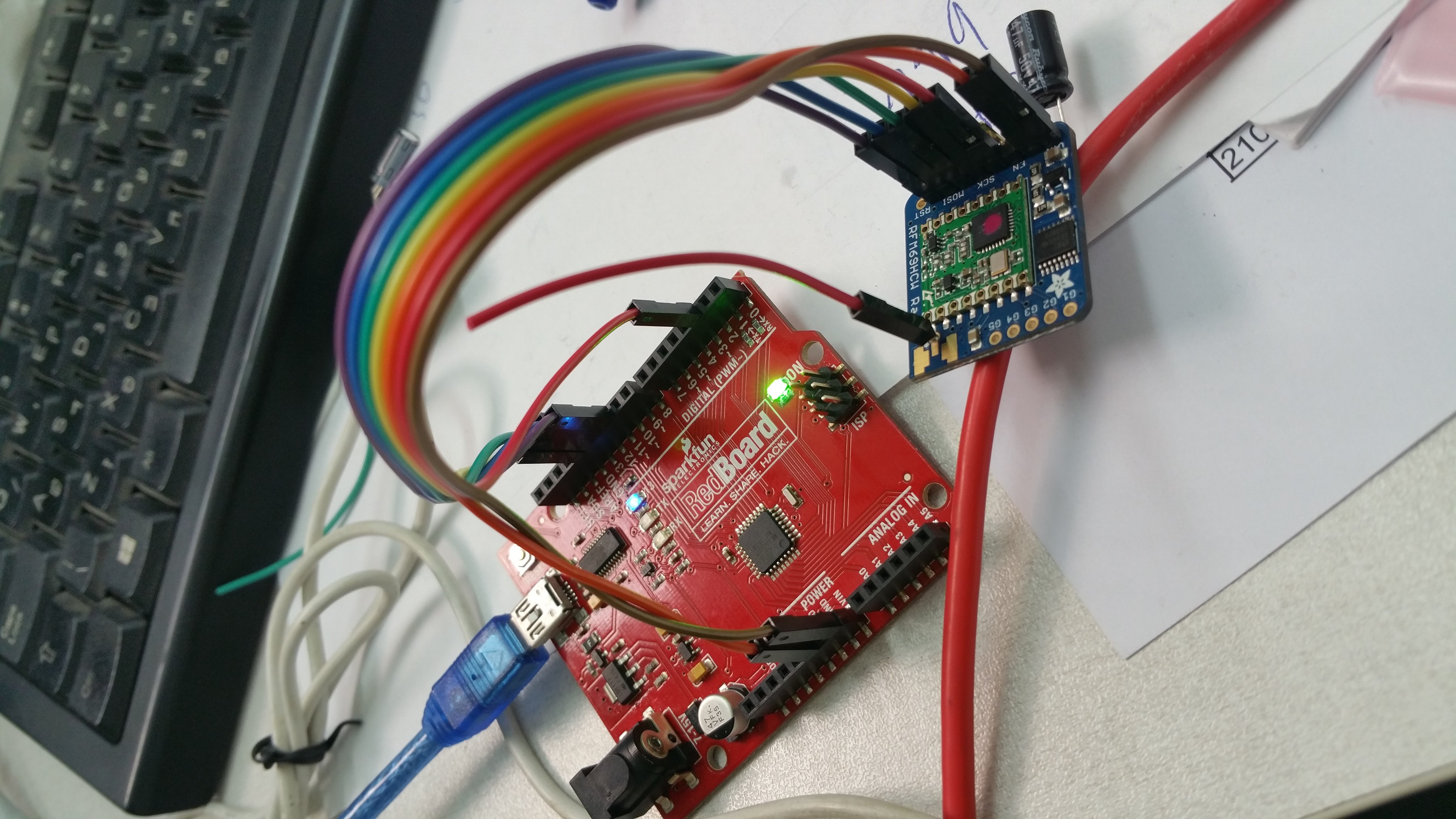
    now i have a running serial-gw and 3 nodes that one of them talks to the gateway directly from a distance which a similar nrf node needed 2 repeaters to do so. exciting! its about 117 meters of direct line, with one plastic transperant door between and only simple standing wire antenna without dipole.

    thanks everyone,

    and a letter to the honorable @Admin (s):
    may i propose a sticky thread dedicated to all compatible hardwares which need special configuration in order to work with mysensors. some examples:
    this thread :blush:
    adafruit feather
    w5100 with rfm69

    i think many members will benefit from such thread for saving time sweat and unnecessary effort for something that should be written somewhere in some dust covered manual

    Troubleshooting

  • [SOLVED] W5100 Ethernet gateway with RFM69 Radio fails at init
    A abrasha

    @Tris
    ok it didnt work with the w5100.h amendment, so i reverted to the original config.
    now im on your new pinout with the a0-a2 thing, and i got identification on domoticz log and ping throught win7 command line. everything looks fine, but when i try mockmysensors to see if it recieves any comminication i dont see anything.
    also the serial log looks wierd:

    IP: 192.168.254.204
    0;255;3;0;9;MCO:BGN:STP
    0;255;3;0;9;MCO:BGN:INIT OK,TSP=1
    0;255;3;0;9;Eth: connect
    0;255;3;0;9;Eth: 0;0;3;0;2;
    0;255;3;0;9;Eth: 0;0;3;0;2;Get Version
    0;255;3;0;9;Eth: 0;0;3;0;18;PING
    0;255;3;0;9;Eth: 0;0;3;0;18;PING
    0;255;3;0;9;Eth: 0;0;3;0;18;PING
    0;255;3;0;9;Eth: 0;0;3;0;18;PING
    0;255;3;0;9;Eth: 0;0;3;0;18;PING
    

    and it goes on and on...
    of course both nodes have gone eeprom clearing

    Troubleshooting

  • [SOLVED] W5100 Ethernet gateway with RFM69 Radio fails at init
    A abrasha

    @Tris thanks a lot. I'll check it on Sunday.

    Btw i use adafruit rfm69hw breakout so no level shifter needed, but i need to post my fix for it because it needs my transport.h mod

    Troubleshooting

  • [SOLVED] W5100 Ethernet gateway with RFM69 Radio fails at init
    A abrasha

    @Tris with or without w5100. H mod?

    Troubleshooting

  • [SOLVED] W5100 Ethernet gateway with RFM69 Radio fails at init
    A abrasha

    @Jonathan-Caes @Frédéric-Grandjean
    if i use w5100 shield on uno - so i cant connect the pins how i want - means w5100 cs stays on pin 10.
    what should i do?

    Troubleshooting

  • [SOLVED] ADAFRUIT rfm69hcw breakout - doesnt respond
    A abrasha

    @tekka

    Tried this on d9 inside the void setup:

    pinMode(9, OUTPUT);
      digitalWrite(9, HIGH);
      delay(100);
      digitalWrite(9, LOW);
      delay(100);


    The adafruit test sketch put this in order to reset the board in the setup phase.
    Didn't work

    Troubleshooting

  • [SOLVED] ADAFRUIT rfm69hcw breakout - doesnt respond
    A abrasha

    @tboha
    Maybe library issue.?
    I checked the same sketch with nrf24 and it was fine

    Troubleshooting

  • [SOLVED] ADAFRUIT rfm69hcw breakout - doesnt respond
    A abrasha

    @tboha
    checked now.
    D13 shows 0v (measuring on the uno itself) and after some seconds, when it lits up forever it shows 0.3v and the serial output prints these two new lines:

    0;255;3;0;9;TSM:FAIL:RE-INIT
    0;255;3;0;9;TSM:INIT

    also , about the VIN discussion, why does mysensors advice to connect 5v to 3,3v regulator to VIN? on the connect the radio page

    about more boards - i only have these 5 adafruit breakouts. all other nodes and GW are working on nrf24. so nothing to compare. and all 5 do the same error

    Troubleshooting

  • [SOLVED] ADAFRUIT rfm69hcw breakout - doesnt respond
    A abrasha

    @tboha
    stripped the CAP
    tried this with EN pin: (connected to D7)

    void setup()
    {
      pinMode(7, OUTPUT);
      digitalWrite(7, LOW);
      delay(500);
      digitalWrite(7, HIGH);
    	// Setup locally attached sensors
    }
    

    nothing..
    and ther is a steady 4.4v on EN (checking from EN to GND

    what does the steady 13 led light means?

    Troubleshooting

  • [SOLVED] ADAFRUIT rfm69hcw breakout - doesnt respond
    A abrasha

    @tboha
    The picture you referred to shows the rfm69HW from my sensors page and the adafruit is rfm69Hcw that's why they're don't identical.

    And I've tried also without capacitor.
    Tomorrow I'll check the EN. Maybe I'll wire it and write it high or whatever needed.
    Thanks a lot

    Troubleshooting

  • [SOLVED] ADAFRUIT rfm69hcw breakout - doesnt respond
    A abrasha

    @tboha
    on uno:
    VIN on uno gives 4.55v
    5v gives 4.99v

    on adafruit:
    vin to gnd gives 4.99v
    cs and mosi gets 4.99v
    miso and sck gets 0v

    now checking on the green rfm69 original board in the middle:
    mosi and nss(cs) recieves 3.2v but after some seconds the d13 led lights on and stays on and then mosi gets 2.87v and nss 1.54v
    sck shows 0v and afterwards (d13 led lighting) 0.2v
    miso shows 0v all the time.

    did you meant current measuring? because i didnt succed measuring it by touching with multimeter between the vin on adafruit and 5v on uno (i read somewhere that the MM should be inside the circuit )

    Troubleshooting

  • Sparkfun nrf24 on my sensors
    A abrasha

    @mfalkvidd plus a voltage regulator so i can plug the vcc directly into VIN for more current.

    Hardware

  • Sparkfun nrf24 on my sensors
    A abrasha

    Does anyone knows if this board is compatible with mysensors?

    Sparkfun nrf24

    I think it's a nice board without the power demands of the pa+lna version but more power than the simple nrf. And it's a reliable source to buy from.

    Im looking to improve my network through 433mhz checking and also the option to replace my nrf's to more reliable units

    Hardware

  • [SOLVED] ADAFRUIT rfm69hcw breakout - doesnt respond
    A abrasha

    @tboha
    Well, no, the Vin on the adafruit (brown wire) is connected to the vin pin on the uno. I've tried also connecting it to the 5v pin with no success. Also tried switching gnd sockets on the uno.
    Im close to sign this issue with recall to adafruit - i ordered 4 boards and they're all with the same behavior. Or maybe i shorted out the ground when i soldered the antenna?

    Troubleshooting

  • [SOLVED] ADAFRUIT rfm69hcw breakout - doesnt respond
    A abrasha

    @scalz @Fabien

    ok, after trying ide 1.8.1 and mysensors 2.0, and adafruit reciever\sender example sketch on this specific board web page, i found something strange...

    this is the output from the node(currently gatewayserial sketch) when i open serial monitor:

    0;255;3;0;9;MCO:BGN:INIT GW,CP=RRNGA--,VER=2.1.0
    0;255;3;0;9;TSM:INIT
    0;255;3;0;9;TSF:WUR:MS=0
    0;255;3;0;9;!TSM:INIT:TSP FAIL
    0;255;3;0;9;TSM:FAIL:CNT=1
    0;255;3;0;9;TSM:FAIL:PDT
    

    now, when i pull the GND dupont cable from the uno i see this:

    0;255;3;0;9;TSM:FAIL:RE-INIT
    0;255;3;0;9;TSM:INIT
    0;255;3;0;9;MCO:BGN:INIT GW,CP=RRNGA--,VER=2.1.0
    0;255;3;0;9;TSM:INIT
    0;255;3;0;9;TSF:WUR:MS=0
    0;255;3;0;9;TSM:INIT:TSP OK
    0;255;3;0;9;TSM:INIT:GW MODE
    0;255;3;0;9;TSM:READY:ID=0,PAR=0,DIS=0
    0;255;3;0;9;MCO:REG:NOT NEEDED
    0;255;3;0;14;Gateway startup complete.
    0;255;0;0;18;2.1.0
    0;255;3;0;9;MCO:BGN:STP
    0;255;3;0;9;MCO:BGN:INIT OK,TSP=1
    

    looks promising to see "gateway startup complete" so i checked domoticz log and it showed

    2017-01-17 13:08:05.102 MySensors: Gateway Ready...
    2017-01-17 13:08:05.194 MySensors: Gateway Version: 2.1.0

    yeah!! an electric circuit running with no ground output!! i should get a nobbel for this...

    so i took another arduino and uploaded it with mock-mysensors sketch, and again the same outpt until i pull the GND out and then it keeps sending msg's and FPAR but without success, and of course domoticz log shows no incoming transmission.

    domoticz log shows no connection to the s-GW until GND is pulled out, and alos the other node doesnt send until GND is out.
    now i noticed that if i plug GND again without resetting the arduino, the on board led(pin13) lights up steady and of course the serial monitor freezes. some sort of electric short?

    :rage:

    Troubleshooting

  • [SOLVED] ADAFRUIT rfm69hcw breakout - doesnt respond
    A abrasha

    @scalz
    What do you Mean reinstall?

    Troubleshooting

  • [SOLVED] ADAFRUIT rfm69hcw breakout - doesnt respond
    A abrasha

    @Fabien @scalz

    Fixed the antenna with correct length and single core wire.
    Tried also with nano.

    Nothing. Tried even downgrading avr boards to 1.6.9.
    Still nothing.
    Is it something with 2.1 or this adafruit board?

    Tomorrow I'll try 1.5 or 2

    Maybe it's how I upgraded the library - i just deleted the mysensors folder and copied the new one.

    Also I have some strange error since then - something like " spurious mystools in mysensors folder"

    Troubleshooting

  • [SOLVED] ADAFRUIT rfm69hcw breakout - doesnt respond
    A abrasha

    @scalz
    I only have nano and uno so no 3.3v to test. But I think this adafruit board is meant to receive 5v on all pins.
    What do you mean one core on the antenna wire? Solid wire instead of couple of tiny wires inside? Can it make this error happen?

    Troubleshooting

  • [SOLVED] ADAFRUIT rfm69hcw breakout - doesnt respond
    A abrasha

    im starting my movement toward replacing my nrf24 to rfm69-433mhz, and on the same time upgrade to 2.1 library,

    i have adafruit rfm69hcw conneced to arduino uno: 0_1484485217885_20170115_145327.jpg

    by this pinout:

    0_1484485252441_תרשים חיבורים - rfm69.png
    **the word אנטנה!! in the right side of the pcb means antenna...

    now i uploaded the serial gateway sketch and added all the neccesarry rows:

    #define MY_RADIO_RFM69
    #define MY_RFM69_FREQUENCY RF69_433MHZ
    #define MY_IS_RFM69HW
    #define MY_RFM69_NETWORKID 100

    now all i got is this serial output:

    0;255;3;0;9;MCO:BGN:INIT GW,CP=RRNGA--,VER=2.1.0
    0;255;3;0;9;TSM:INIT
    0;255;3;0;9;TSF:WUR:MS=0
    0;255;3;0;9;!TSM:INIT:TSP FAIL
    0;255;3;0;9;TSM:FAIL:CNT=1
    0;255;3;0;9;TSM:FAIL:PDT
    0;255;3;0;9;TSM:FAIL:RE-INIT
    0;255;3;0;9;TSM:INIT
    

    both happens with serial gateway sketch and ethernet gateway sketch.

    maybe my antenna isnt good? its an ordinary dupont cable with the male connector soldered inside the ANT hole
    uno powered by PC usb, and the rfm69 vin connected to VIN (5V also didnt do anything)

    Troubleshooting

  • Blinds control
    A abrasha

    Hi. I'm about to build a double relay node for Controlling motorized blind - by simply connecting the relay wire to the wall button (inside the wall of course).
    Now, the easy way is to create 2 switch devices - one for up and one for down.

    So my question is, can I define the switch to be some "blind" type and use it for both up and down? That's more nice looking. And if i can do some percentage closing/opening it would be cooler indeed.

    Domoticz
  • Login

  • Don't have an account? Register

  • Login or register to search.
  • First post
    Last post
0
  • MySensors
  • OpenHardware.io
  • Categories
  • Recent
  • Tags
  • Popular