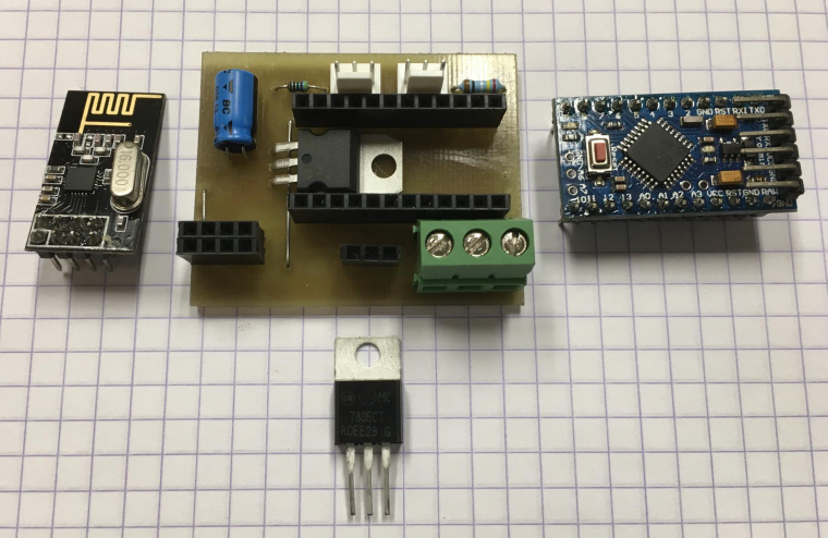
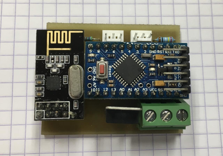
Today I build a basic node for temperature (DS18B20) and analog input. Most of my nodes feature a DS18B20 connection as it only 'costs' a 4k7 resistor and a connector.
PCB is etched.
B
boozz
@boozz
Posts
-
What did you build today (Pictures) ? -
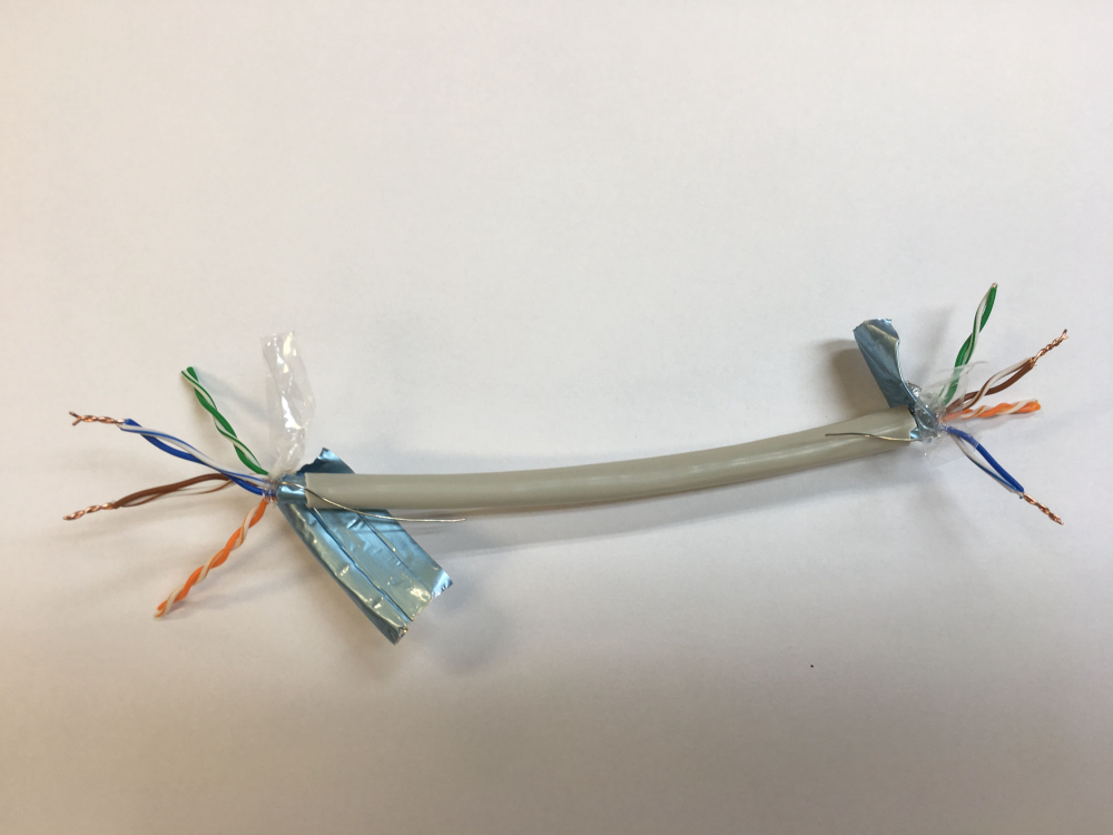
5v cableand a simple 'trick' to allow higher currents if necessary:
A network cable has 8 leads in it. Any spare pair of leads not used for something else (e.g. data....) can be used to increase the current strength of the 5V and return (GND) line.
-
What did you build today (Pictures) ?Today I finally found some time to put a few modules together.
A cheap solar cell (€1.35 a piece) with recharcheable battery which feeds via a step-up converter (€0.70 /pc) a pro-mini (5VDC). The DS18B20 is read every 5 minutes.
Now I’m Interested how long this sensor will do its job.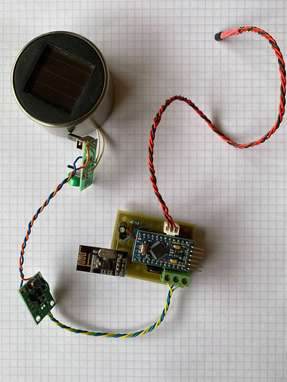
-
[solved]Capacitor for radio moduleThe purpose of the capacitor (use an elco for this) is to make sure that the voltage remains smooth (no ripple or sudden drops) by buffering a small amount of energy (capacity). From that point of view: the larger the value, the better.
The next question would be if your source is able to supply the current to keep the capacitor filled. From that point of view a small capacitor would be the better choice, but too small would give you too less buffered capacity....The practicial approach is to test it; I've done that and I found out that a 4.7 uF was good enough. Up to values of 100 uF (never tested with higher values of elco's) worked as well, but these are larger....
Better is worse than 'good enough'
Have fun!
BR,
Boozz
-
some problem in sensor + repeater !@Reza
just try it and see what happens -
Dallas sensors puzzle - sensors.begin()@zboblamont
Although I didn't completely analyse your sketsch I remember from some time ago that I ran into problems once I moved the one-wire- pin from 3 to another pin. No idea why, and never actually took the time to troubleshoot this, but when I brought it back to pin 3 all my problems disappeared with the dallas sensors.Hope it helps.
BR,
Boozz
-
💬 Arduino UNO NRF24L01+ Shield@mfalkvidd
I think you’re right. I only had a look at the first image and there the C1 location was not visible as the nrf-module was in front of it.
My bad 😬 -
to debug or not to debugThank you both for the contributions.
@mfalkvidd: Thanks a lot for pointing me towards the technique to turn it on /off. This will become very handy in the future for sure.
BR,
Boozz
-
Creating Wireless Sensor Network@codergirl56
Reading your question, I think your starting point is to have a look at the pingpong example (see below for the direct link) which comes with the mysensors library and try to modify it such that it starts sending the RFID data.direct link to pingpong example
First you'd need to install the mysensors library of course, see the download page. How to do that is in the "Getting Started" as mentioned by @AWI. Just start reading and you'll be guided to it.
good luck
Boozz
-
Ultra low temperature (-80ºC) monitoring probes@emc2
According to some datasheets a K-type thermocouple would be my first choice. Look here for a table on K-typesa MAX31855 can be used to interface to the arduino. See some explanations here and here.
I haven't read all of the information above, but the datasheet for the MAX31855 tells us that it can be used from -270º up to 700º.
Could be a starting point I think.
Good luck,
Boozz
-
How to find out if message was successfully delivered?You could also use code like this:
bool delivered = gw.send(kwhMsg.set(kwh, 4)),true);
if !(delivered){
// put code here to take corrective actions, ...
}
BR,
Boozz
-
connection problem between node and serial gateway@Reza
Maybe it's worth going through the "Getting Started" section which can be found on top of the homepage for MySensors. If you read your way through all the info given, and a lot is explained in detail in those sections, then you come across the section where the network topology is explained.I made it somewhat simpler for you: just click here to reveal a nice picture showing the network topology
BR,
Boozz
-
Uno stops sendingI agree that powering the nrf via the uno's onboard 3.3V can be problematic. Unfortunately I experience the same issues with my pro-mini's and here the nrf's are powered via an external 3.3V LDO voltage regulator (MCP1700, TO-92). Now and then a sensor or repeater simply stops.
Cut and paste from Jim Danforth: :smiley: Hitting reset button makes it reconnect and instantly update.I've never tested my nrf's (china, ebay) but I guess this could be the source of the problems we're experiencing.
I think it's worth trying the quality meter as discussed in this tread
BR,
Boozz
-
some problem in sensor + repeater !@Reza
You can change your code yourself: replace gw.sleep(sleep_time) by gw.wait(sleep_time).Given the posted code I think you use the MySensors 1.5 libraries.
BR,
Boozz
-
connection problem between node and serial gatewayYou'll find that info here.
A sensor can act as a repeater, but it doesn't have to do so. I have to use some repeaters around my house as I've got to get the signal going through very thick glass (with a coating on it) and through walls of stone. It's a bit of a faraday's cage I live in :-).
Most of the repeaters have a DS18B20 sensor on it so I can log the temperature at that point as well. This makes them a little bit more functional than 'just being a repeater'.
If your nodes function for some time, the capacitor is Ok. Occasionally I use 10uF, but 4.7 uF should be Ok. I think the problem is your walls. Use an amplified nrf24L01+ version or place an repeater at one or both sides of the wall.
Try what happens if you place your node at lets say 5 mtrs. from the repeater. Does it still disconnect after some time?Succes!!
BR,
Boozz
-
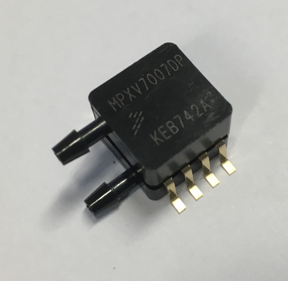
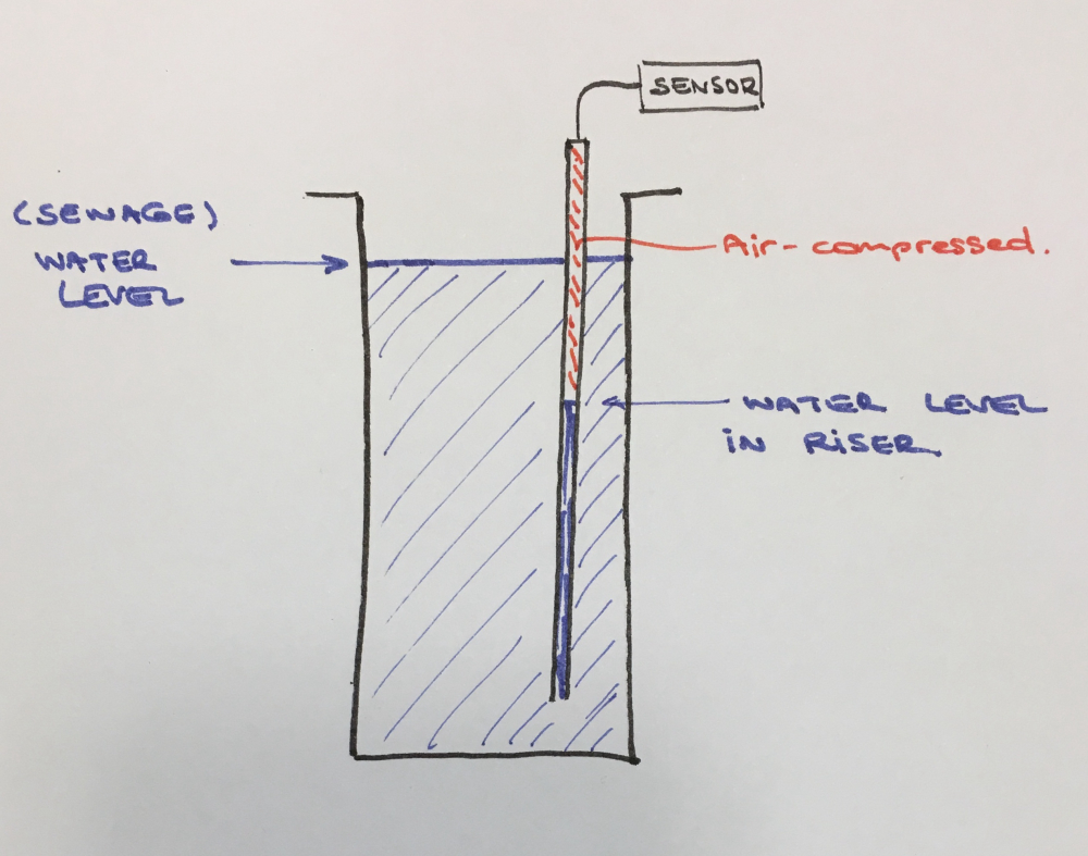
Water pressure sensors?Have a look at freescale sensors. i.e. MXP-type sensors. You could ask for samples (they will provide up to 5 pcs. for free). Cost around $15 pcs. normally.
You'd mount such a sensor on top of a riser (air-tight) and when the (sewage) water rises, the air-pocket is compressed proportionally. This is how I measure the ground-water level at my location and it helps me to keep my basement free of water. Works flawlessly!
BR,
Boozz
-
some problem in sensor + repeater !@Reza
Instead of asking people in the forum at every step you take, you could use the trial and error method.BR,
Boozz
-
Unknown battery drain@richard-van-der-plas
get yourself a boost converter. Something like this:DC-DC 0.9V -> 5V
I remove the USB connector, disable the LED's and it increases the battery voltage to 5VDC.You need an extra cap on the 5VDC output as it will otherwise compromise the working of the nrf24L01+.I use 5V pro-mini's as well on batteries and my NiMH batteries last at least one month, doing a somewhat similar thing as what you have in mind.
I have to power a pressure sensor which is used to monitor the ground-water level around my house. This sensor takes slightly less power than your water sensor.I do agree with @mfalkvidd a 3.3V pro-mini would be better for this as you do not have to get the 5VDC down to 3.3VDC for the nrf24L01+, but the 5V version is the next best option in my opinion.
-
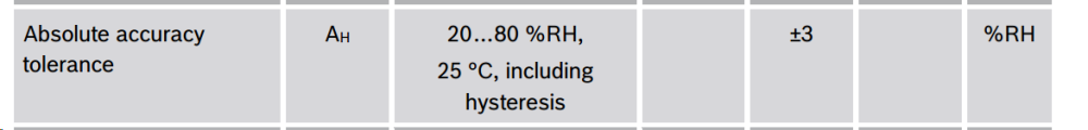
BME280 sensor variabilityLooks to me as if the sensors perform as specified (acc. to the datasheet etc.):
Relative Humidity: absolute accuracy tolerance of the RH: +/- 3
Temperature: in the range 0-65ºC: +/- 1.0 ºC
BTW: The datasheet says the following about the temperature:

BR,
Boozz