Posts made by boozz
-
RE: What did you build today (Pictures) ?
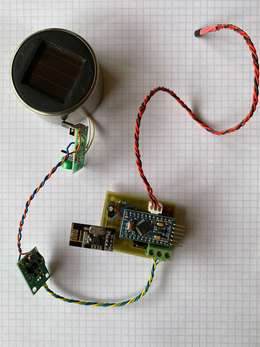
Today I finally found some time to put a few modules together.
A cheap solar cell (€1.35 a piece) with recharcheable battery which feeds via a step-up converter (€0.70 /pc) a pro-mini (5VDC). The DS18B20 is read every 5 minutes.
Now I’m Interested how long this sensor will do its job. -
RE: Battery powered latching relay node
@Yveaux
May I ask why you use the IR4427S driver instead of two transistors or (N-Channel)mosfets? Is this because of PCB space, or any other (power) reason?BR,
Boozz
-
RE: Modular sketch to be configured with JSON (idea)
@kimot @monte
It appears to me as what has been described by @monte is almost completely covered by the Tasmota project: https://github.com/arendst/Tasmota -

RE: New enclosures
@alexno Is this (high pressure) injection moulded? What's the material?
-
RE: Dallas sensors puzzle - sensors.begin()
@zboblamont
Although I didn't completely analyse your sketsch I remember from some time ago that I ran into problems once I moved the one-wire- pin from 3 to another pin. No idea why, and never actually took the time to troubleshoot this, but when I brought it back to pin 3 all my problems disappeared with the dallas sensors.Hope it helps.
BR,
Boozz
-
RE: My experiences with MySensors
@kimot said in My experiences with MySensors:
And for "MESH" topology.
Arduino "painlessMesh" library for ESPs existsWIll have a look at that too in the near future. Thanks for hinting me towards this.
Boozz
-
RE: My experiences with MySensors
@kimot said in My experiences with MySensors:
MySensors is goot for nodes a far away in my garden and for nodes with low energy consumption and fast reaction when wake up.
When MySensors node is sleeping and then wake up, it immediately continues in program flow immediately from the place of "sleep" command.
Wemos, when sleeping an wake ups, reboots and must connect to AP, which takes 8s to 2s when we do some tweakings.Ok, so if I do not misinterpret your words, it's better / easier to use mySensors for the tasks as specified above and use WEMOS / 8266 for other tasks. Some pretty distinct way of where and how to use it.
Thanks a lot for the info provided. I appreciate that. I will give this a try sooner or later for sure.
Up to now my experience with mySensors is positive. Yes, now and then the radio's give me some troubles, but that's part of it. Still a very inexpensive way to collect data and switch on the lights in my garden house, dim some LED's all over the house and get alarmed once the ground-water reaches a level so I have to watch out my basement isn't flooded.Thanks
Booz
-
RE: My experiences with MySensors
@rodaman: May I remind you of my questions:
@rodaman
...
However, I'm interested in your Wemos setup.
I've got some questions from which I'm sure you can give me the right quidance:
I guess it used some bandwith in your Wifi network? can I use it similar as mySensors topology or even with mySensors libraries?
Can it be used with batteries (sleep modes and so on) for a long time?thank you in advance for your values answers,
BR, Boozz
Unfortunately no reaction from your side till today. In the meanwhile I've searched the internet for a ESP8266 or ESP32 mesh network as an alternative for the mySensors network. I cannot find a good working open source (read Arduino based) startpoint, so I'm wondering if you could direct me to a good starting point.
Thanks,
Boozz
-
RE: My experiences with MySensors
@rodaman
Although fully agree with @mickecarlsson and @tbowmo (I have been lucky with really cheap nrf24L01+ modules I think) and have a similar experience as @TheoL (MySensors works fine with nr24L01+ modules) I can state that mySensors is very much alive.However, I'm interested in your Wemos setup.
I've got some questions from which I'm sure you can give me the right quidance:
I guess it used some bandwith in your Wifi network? can I use it similar as mySensors topology or even with mySensors libraries?
Can it be used with batteries (sleep modes and so on) for a long time?thank you in advance for your values answers,
BR, Boozz
-
RE: How to get 5v pulse from a water meter
@pelle84 said in How to get 5v pulse from a water meter:
someone that can help?
i add the sensor manual
its the PR7 version.I think you need to be a little bit more specific about what PR7 type you bought. I see a multiple of schematics in the manual, and only you know which one to use as you know what device you've bought.
Suggestion: publish the schematic from the manual that corresponds with your device.Another question: How dit you connect the device to the arduino, and how is it powered (internal battery or via the arduino or via an external power supply). Again, as you're not specific about the device you have, we can't be of help I'm afraid.
Suggestion: draw the schematic or make an image, and publish that.
BR, Boozz
-
RE: Question: FL5150 LED Dimmer - replace a analog potentiometer with a digital one
@jimmyjames said in Question: FL5150 LED Dimmer - replace a analog potentiometer with a digital one:
..., the only downside is then you need a power supply for the ESP32 and isolated one and another power supply for the I2C isolator on the FL5150dimmer side as it uses upto 6mA 5vdc and the DAC use 1mA so that is inconvenient.
Have you considered using isolated DC-DC converters? Then you may be able to keep all in the concept of "only 240v wires go in and out".
Will take a look at the video within short
BR, boozz
-
RE: Question: FL5150 LED Dimmer - replace a analog potentiometer with a digital one
@jimmyjames said in [Question:
I intend on improving it to a more usable and safer point.
Could you elaborate a bit on the last part, the safety issue; I think you mean that it is not a very safe circuit at the moment: No isolation between 230VAC and the microprocessor part or am I missing something?
BR, boozz
-
RE: Mini lightshow project ideas
@mrhutchinsonmn
I really like the idea! Would be great to see a video once you've got it working.To get some idea about the scale of the project: How many instruments are involved?
-
RE: BME 680 SPECIFIC INFORMATION SEARCHED
@maartend
See for the link below. It's one of the first hits when searching on google with the words "BME680 raspberry pi":Reading a sensor on a raspberry pi 4B can't be much different from older raspberry versions I guess. The OS might have changed with the new version. Python hasn't.
-
RE: 1.2 MPa pressure transducer
- could be some noise (EMC). What's your sample rate?
- could be the change in pressure in the water pipe due to some users upstream and your own usage (downstream).
agree with @zboblamont: if possible have a look at what your real pressure fluctuation is.
-
RE: 1.2 MPa pressure transducer
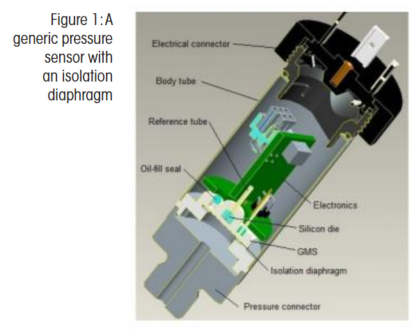
Maybe something like this?
This comes from: https://issuu.com/process1/docs/pii-june-2019
Page 14 and further
-
RE: What did you build today (Pictures) ?
@gohan
I was referring to @berkseo 's situation and images/examples. I just wondered why this person would put this amount of effort in creating a device that would probably not be functional at the moment it should be functional. I'm just thinking about corrosion of the pcb, a drained battery, change of properties of the 'sensor' due to time-effects etc.
Do not misunderstand me: I'm absolutely enthousiastic about this device (and I'm impressed by how small it is and the design), but I'm a bit concerned about the effects that could negatively affect the behaviour of it. -
RE: What did you build today (Pictures) ?
I do not want to be too offensive, but it seems to me as if your skills in electronics and 3D-printing is way better developed than your trust in the plumbing
Now for the serious part: how often do you experience water leaks? And how long do the batteries in this design last?
Boozz
-
RE: nRF24L01+ Communication Failure: Root Cause and “Solution”
@mfalkvidd
Thanks!
I guessed something like that, but couldn't find it in the API section -
RE: nRF24L01+ Communication Failure: Root Cause and “Solution”
Ok, great! I presume it requires me to set this pin somewhere in the #define section? Could you hint me what variable is used for that in the config section? I guess the MY_RFM69_IRQ_PIN is not the proper one.
About the other interrupt pins: That's an interesting one. I only know of pin 2 and 3 being the interrupt pins on a pro-mini / nano. Is it possible to use other pins for that? If so, how to achieve that?
-
RE: nRF24L01+ Communication Failure: Root Cause and “Solution”
That would mean IRQ on pin 2 (pro-mini or nano)?
Could be a wire-bridge for a lot of my boards I think... -
RE: Cannot flash atmega328 on new custom board
@adamant
Are you sure the Atmega328 has a bootloader installed yet?Have a look at this link. Might be of help.
Boozz
-
RE: 💬 Arduino UNO NRF24L01+ Shield
You mean this item?:
I never used the CE pin via a level converter up till now. I use 3 of them and some have ran for over 3 years now. So I guess they must be 5V tolerant.
Of course, power pin should be 3v3. -
RE: 💬 Arduino UNO NRF24L01+ Shield
@mfalkvidd
I think you’re right. I only had a look at the first image and there the C1 location was not visible as the nrf-module was in front of it.
My bad -
RE: 💬 Arduino UNO NRF24L01+ Shield
@openhardware-io
Looks as a nice and clean design. Too bad you didn't place a capacitor near the power pins of the nrf24L01+ module.
With my UNO I only got this module working when adding the capacitor... -
RE: I need some help about sensors
@rocksolid
Have a look at a RCWL-0516 "radar" sensor. This fits exactly your latest specs you posted. It's a rectangle, long and thin.I'm using these sensors to detect the presence of living objects.
-
RE: [SOLVED] ds18b20 vs si7021 loss of granularity in measurement
@yveaux
Thanks for the hint and explanation. I appreciate that!I always used the search term: "conversion" (English is not my native language). I tried "casting" in combination with "c#" and I was almost immediately directed to my favorit c++ internet source (cplusplus.com)
http://www.cplusplus.com/doc/tutorial/typecasting/
Many thanks!
Boozz
-
RE: [SOLVED] ds18b20 vs si7021 loss of granularity in measurement
@Yveaux
Good to see it solved for @waspieConversion from int (or byte) to float and vise versa is something that often brings me a headache.
I literaly spend many hours searching for a good guide in via google, but never really found one.Are you maybe aware of a good guide how to properly do the conversions between different types (byte from floats etc. without getting involved in memory hungry libraries).
BR,
Boozz
-
RE: [SOLVED] ds18b20 vs si7021 loss of granularity in measurement
@waspie said in ds18b20 vs si7021 loss of granularity in measurement:
temperature = data.celsiusHundredths/100;
In my opinion does the above line not cohere with the statement that the steps are greater than .5 degrees fahrenheit.
Have you tried using:
temperature = data.getFahrenheitHundredths/100;
and what was the result.
Could it be you've been playing with the examples as provided with the library from LowPowerLab and you accidentally forgot to "turn the heater off"? I'm guessing at the moment, but you could end up with the device being heated up in the range of 70ºC (which is 158 degrees fahrenheit... )
BR,
Boozz
-
RE: Over current protection
I think that if you'd type these 3 words as you've used in the title of your post in any search machine you would get the info you're looking for.
-
RE: BME280 sensor variability
Looks to me as if the sensors perform as specified (acc. to the datasheet etc.):
Relative Humidity: absolute accuracy tolerance of the RH: +/- 3
Temperature: in the range 0-65ºC: +/- 1.0 ºC
BTW: The datasheet says the following about the temperature:
BR,
Boozz
-
RE: twm 1000 flowtransmitter
Hi,
If you'd like someone to answer on this, I think it's good to give a little more background.
As you're getting readings it tells me that it's been hooked up, but not if it's hooked up correctly. Please provide some info on how that's done. Images as well as schematics will be helpful.
BR,
boozz
-
RE: Two Mysensors Network in Same Location
I have two networks running in the same area, with the same purpose as yours.
One is running at Channel 13, the other at Channel 58. Works perfectly.
Boozz
-
RE: Sensor for measuring sensitive touch
Maybe you have to do some (internet) research on how the screens of smartphones or tablets work. something like this. Ok it's a little bit over the edge for a Arduino, but it gives some direction I hope.
BR
Boozz
-
RE: Multiple sensors
@bogus-exception
What do you mean by a HE? Human Engineering? Heavy equipment? High End (system)? Happy Ending ?BR,
Boozz
-
RE: Multiple sensors
@reshma-oueseph
This is probably a module that uses CAN-bus as a bus interface. CAN-bus is used in automotive te reduce the number of wires in order to minimise cost. Other busses, used in industry are MODBUS, profibus, etc.In a way you could see mySensors as a bus system as well as it is wireless Could be very beneficial for your challenge: each machine one or more sensor-node(s) - depends on the number of wires you'd like to monitor and the level of multiplexing you'd allow - and a gateway that is connected to a dedicated controller. This controller (I think not one of the controllers as used in the mySensors community) is used to translate the messages to instructions where to repair the yarns.
First thing to do for you is understand your real problem (yarns are breaking) and how you'd like to interact on this.
I think it's good to re-read the remarks @Bogus-Exception made! I strongly suggest you to read that again!BR,
Boozz
-
RE: Multiple sensors
Hi Reshma,
I googled your question ("connect multiple hall sensor to digital") and guess what happened...
this was the first hit I got from google
It may not be exactly what you're looking at, but what I try to explain here is that using google for this may be more helpful than posting it in this forum as I think your question is more related to using arduino in general.
BR,
Boozz
-
RE: Looking for waterproof connectors
Consider the use of resQ tape. Not sure if this is available world-wide, but the use of it is very versatile.
I've used heat shrink with and without the glue layer inside. Works for some time, but water gets in. Only the resQ tape has proven to keep the joints (cable entries of the connectors) watertight!
See this video:
ResQ-tape EN Self fusing silicone tape – 02:21
— AGROCENTERBR,
Boozz
-
RE: Water pressure sensors?
above link is an example of a sensor which could be used. Not sure what the level change will be, but the "new law" as you refer to will tell you what accuracy is needed. This sounds to me as a perfect example of a LoRa sensor.
The sensor goes in the bore hole (same as the manual cord measuremens) and stays there. The electronics (4-20 mA preferrably as 1000 ft is quite a distance) can remain at ground level.If you have any idea what the change of level is in the well, you can easily find the range for the sensor.
BR,
Boozz
-
RE: Water pressure sensors?
Have a look at freescale sensors. i.e. MXP-type sensors. You could ask for samples (they will provide up to 5 pcs. for free). Cost around $15 pcs. normally.
You'd mount such a sensor on top of a riser (air-tight) and when the (sewage) water rises, the air-pocket is compressed proportionally. This is how I measure the ground-water level at my location and it helps me to keep my basement free of water. Works flawlessly!
BR,
Boozz
-
RE: Using a sensor to sense the presence of copper wire.
@moparjay
have you thought about using a jfet? -
RE: Trouble wiring a Dalla 18B20 to Arduino D1 Mini
@sirzlimz
Nothing wrong with the wiring. As @zboblamont already stated you've used the parasitic mode.
All my DS18B20's are connected that way (using pro-mini's).Any code available?
BR,
Boozz
-
RE: 5v cable
and a simple 'trick' to allow higher currents if necessary:
A network cable has 8 leads in it. Any spare pair of leads not used for something else (e.g. data....) can be used to increase the current strength of the 5V and return (GND) line.
-
RE: Frequency usage regulations
@bakcsa
Thanks a lot for your explanation and the directions.
Thumbs up! -
RE: Frequency usage regulations
It's good to come up with this and I fully agree that we should respect the regulations. You explained it well by the 'stealing' analogy.
I think the links you've inserted are good, but they provide an awfull lot of information which most probably is not all applicable for our mySensors users. Would it be an option to elaborate what the limits are for us in e.g. using the nrf24L01+ antenna's?
I'm using 3 nrf24L01+PA+LNA SMA Antennas (amplified) as well as approx. 15 small nrf24L01+ modules in my network. I'm wondering am I still acting within the regulations if I use an amplified nrf24L01+ LNA etc. in max power mode (NRF_PA_MAX) using Channel 24?
I would really appreciate it if you can tell me if I comply with the regulations.
Thanks,
Boozz
-
RE: Ocr for Arduino or raspberry question
@ecabanas
Sounds like vision...google: vision automation
-
RE: Trigger when mouse trap caught a mouse
@bjacobse Although you have 230VAC in your garage, I would go for the option @gohan mentioned; a reed switch with a magnet. The node itself can be carried around with the mouse trap without all the wire hassle and need for an power adapter.
If you use the reed switch on an interrupt pin, it can be used to wake up the node and send the message. Afterwards you can bring it back to sleep. Saves batteriesGood luck with it.
BTW. never thought of a plastic version for a mouse trap. I only know these ones:
-
RE: What did you build today (Pictures) ?
@dbemowsk
Well it looks as if your 3D-printer works fineWhat I would be slightly worried about is if with the given size of the rods the stiffness of the structure would be enough.
Hope to see more from this project in the near future.
Good luck! -
RE: Unknown battery drain
You'd still need the 7805 after the rectifier...
-
RE: Unknown battery drain
@richard-van-der-plas
get yourself a boost converter. Something like this:DC-DC 0.9V -> 5V
I remove the USB connector, disable the LED's and it increases the battery voltage to 5VDC.You need an extra cap on the 5VDC output as it will otherwise compromise the working of the nrf24L01+.I use 5V pro-mini's as well on batteries and my NiMH batteries last at least one month, doing a somewhat similar thing as what you have in mind.
I have to power a pressure sensor which is used to monitor the ground-water level around my house. This sensor takes slightly less power than your water sensor.I do agree with @mfalkvidd a 3.3V pro-mini would be better for this as you do not have to get the 5VDC down to 3.3VDC for the nrf24L01+, but the 5V version is the next best option in my opinion.
-
RE: Use another node than gateway for control
@mfalkvidd
Serial input will come from a windows based PC. Probably the same as the one that acts as the datalogger.
The actuator could be any actuator-node.To give you some more info:
I have some lights in my shed (mancave actually.... ) that should turn on when pressing a button, somewhere nearby, i.e. near the door. This button is connected to a node that sends the command to the actuator node. setdestination will play a role in this node.
There's also an automation scheme to turn on (and more important: off) the lights. As the shed is quite far away it is very handy to turn off the lights when I have returned to my home and forgotten to turn of the lights (for whatever reason). For this purpose I will use this specific node. Once I manage to controll the lights in the shed, I will be able to controll some more things around. -
RE: Use another node than gateway for control
hey thanks!
I didn't think of using message.destination... I used it in the past to have 2 nodes talking to each other. Now I need some code to get serial input translated to messages.
I think I know where I can find such code for that.
If that idea works I'll post the sketch.
Boozz
-
Use another node than gateway for control
Hi all,
In a MySensors network a controller is connected with a gateway to read messages from sensor nodes and send messages to actuators.
In my MySensors network I use a serial gateway mainly for reading the messages and for the sake of simplicity I would like to keep it that way. (I use a labview application for logging purposes).
As my network grows I want to add some actuators, but I do not want to control them via the gateway as described before.
Would it be possible to send the control-messages around using another node than the gateway using serial communication? Or in other words: would it be possible to send messages in a similar way as would be done via the gateway but now using a dedicated node for that?
I read through the forum but could not find a real answer unfortunately
Best regards,
Boozz
-
RE: What did you build today (Pictures) ?
Yes these are 'molex' pcb connectors.
An ebay alternative can be found at: Ebay shop cayin34
-
RE: What did you build today (Pictures) ?
Today I build a basic node for temperature (DS18B20) and analog input. Most of my nodes feature a DS18B20 connection as it only 'costs' a 4k7 resistor and a connector.
PCB is etched.
-
Gateway echoing to specific node
Hi all,
I've been using mysensors for more than 3 years now, but mostly for datalogging. I never used a controller, but only fetched all messages via the serial gateway using LabView. Node numbering (both end nodes and repeaters) was done by using MY_NODE_ID and MY_PARENT_NODE_ID and MY_PARENT_NODE_ID_IS_STATIC.
all works like charm.Now I want to push my network into domitics. I have a rapsberry-pi lying around, but don't want to throw away my datalogging piece of software, so my setup would preferrably something like that all messages arriving in the serial gateway will be echoed towards a specific node (let's call it node # 253) which is put into debug-mode and from which I can easily read the messages I formerly got from the serial gateway?
The raspberry pi will log data as well, but enables me to switch some lights, turns on the heater and so on.
Would that scenario be possible, or are there other methods to get this working?
BR,
Boozz
-
RE: How to stop receiving messages temporarily?
@rzylius
maybe too simple, but can't you put your specific code within a 'while' loop?
Something like:unsigned long Wait_time; unsigned long Start_time; ... ... // Start_time = millis(); Wait_time = millis() - Start_time; while (Wait_time < 5000){ //insert your code for the routine of actions of roughly 5000 ms here Wait_time = millis() - Start_time; }
BR,
Boozz -
RE: HELLLLLPPPPPP - Need help with calculation of temp sensor and want to add extra sensors
although I always attach 3 wires to the Dallas DS18B20 sensors (guess you'll be using these...) I think the dallas temp sensor can be run using 2 wires.
My 'normal' hardware setup is that I connect the middle leg of the DS18B20 to pin 3 of the 'arduino' (could be any other DI pin of course) from 5V a 4k7 resistor on the same pin 3 and both outer legs of the DS18B20 on GND.
works great for me.BR
Boozz
-
RE: Serial Gateway restarting
@Jan-Gatzke
I now and then experience the same, but in my case it seems that a lack of messages sent to the gateway cause the restartBR,
Boozz
-
RE: Relialbe presense sensor
With respect to the industrial light sensors: Is the problem related to people not moving enough around your office? Lack of movement causes these sensor not to trigger. In that case I think the use of a PIR sensor could probably not help you a lot (although they could be more sensitive, have no real experience with these sensors).
Have you thought about using a tactile switch in the chairs in your office? If someone sits on its chair, every now and then a pulse could be send acting as and presense sensor.
BR,
Boozz
-
RE: DS18B20 onewire gotten this to work with 2.1.1
Have a look at this thread. I think it contains the answer on your fixed ID (children) question.
https://forum.mysensors.org/topic/4834/unique-id-value-ds18b20-temperature-sensors
I personally used the sample programs as provided with the MySensors lib with succes the get the DS18B20 onewire working.
A resistor 4k7 from +5VDC to the middle pin of the DS18B20 connected to D3 from the arduino and both outer pins of the DS18B20 connected to GND works perfect for me.BR,
Boozz
-
RE: How to test/monitor packet loss for each radio node?
Take a look at this forum item: https://forum.mysensors.org/topic/3984/nrf24l01-connection-quality-meter
BR,
Ronald
-
RE: Output voltage problem with StepUp Booster 3.3V
The zener crossed my mind as a simple but effective way to create a stable 3.3V. It might cost some 'bleeding' amps, maybe you could limit it by using a proper series resistor.
See this article for some more details.
BR,
Boozz
-
RE: Output voltage problem with StepUp Booster 3.3V
Strange...
Have you considered using a zener (3.3V) as a protection device next to the step-up booster module?
BR,
Boozz
-
RE: Output voltage problem with StepUp Booster 3.3V
You mean both the pro-mini and nrf24l01+ are fed via this module? In that case you could say that there should be enough load for the power module to get into the 3.3V modus...
-
RE: Output voltage problem with StepUp Booster 3.3V
Are you sure you're not measuring the ripple. These modules are not really known as 'quiet' in terms of stable output voltage, hence the question of the elco.
Have you tried them 'stand-alone' (no radio) and with a decent load (e.g. a resistor drawing a few milliamps or so).
BR,
Boozz
-
RE: Output voltage problem with StepUp Booster 3.3V
@warmaniac
Have you measured this while 'under load' or free running? You could also add a electrolytic condensator (100 uF or so) in order to make sure that you're flattening the ripple.BR,
Boozz
-
RE: Send custom Message to gw
Hi Siod,
Have a look at the "download and api" page here on mysensors (link).
Read through the section API (link) to see how you can send a message to the gateway and if you need some in-dept info go through the section SERIAL PROTOCOL (link). You'll notice that everytime a message is send to the gateway it contains the node-id.
How this is then relayed to your controller is explained in the section "Controller". I guess you can find this for yourself in the menu on top of the homepage.BR,
Boozz
-
RE: 💬 Building a wired RS485 sensor network
@Reza
There are many options for detecting fake radio's. For me it works best to test them in a node that has a good working radio attached (preferrably far as far away from its parent node as possible) and exchange it with the suspected fake one.There's also a thread in this forum that describes a method to test the quality of nrf24L01+ connections. It's a quality meter. I know for sure you can find this one using the search function.
By the way; about the wiring distance between a node and gateway: the fastest way to get an answer is to get multiple answers on such questions is using an universal search engine: www.google.com
-
RE: 💬 Building a wired RS485 sensor network
@gohan
My reaction was only based on your last post in this tread , I totally agree with you on the wired security system where wireless is not an option. -
RE: 💬 Building a wired RS485 sensor network
@gohan
In some cases 'with cable' is the better option. In some cases wireless is the better option. I totally disagree with you on your statement that cable will be ALWAYS be better than wireless. that's nonsense!There are good NRF24 modules out there and there are worse variants, maybe fake ones. I've bought from several ebay stores throughout time. I found out the hard way that some perform good with a 100uF capacitor attached (the simplest variants, costing no more than $0.85), and other perform better with a smaller size capacitor (4.7uF). I get distances with these modules over more than 25 mtrs. with all kinds of obstructions (even faraday alike) in between. All it takes is some (hobby) time to find out what works best (e.g. move a node 1 meter to the left or right or align the antenna somewhat...)
I never ever modified an antenna, never needed to do so. I once bought 2 nrf24L01+-PA-LNA antenna's for wider coverage as I thought I would need that for better/wider coverage, but now, 2 years later, they still are lying around in my workshop.Maybe good to say that these distances can only be achieved with a speed set at 250 kBs and this is only possible using the nrf24L01+ modules!
If I can, I use wireless, as it is cheap, simple, and convenient, but the best reason for going wireless is that I don't need to use a cable! Simple as that.
For the sake of staying somewhat on topic ("Building a wired RS485 sensor network")...
There are occasions in which a wired (RS485) network would be the better choice. In my opinion one occasion is when you need instantly acknowledge that a command really was delivered to a node.BR,
Boozz
-
RE: 1.5.4 and 2.0 on the same computer
@gloob
thanks for the hint. I've done this today. Renamed the Mysensor files (added an 'X' at the end of every .h and .cpp files) and dependencies insides these files and everything compiles again under 1.5.4, so next thing is to install 2.0.BR,
Boozz
-
RE: Uno stops sending
I agree that powering the nrf via the uno's onboard 3.3V can be problematic. Unfortunately I experience the same issues with my pro-mini's and here the nrf's are powered via an external 3.3V LDO voltage regulator (MCP1700, TO-92). Now and then a sensor or repeater simply stops.
Cut and paste from Jim Danforth: Hitting reset button makes it reconnect and instantly update.I've never tested my nrf's (china, ebay) but I guess this could be the source of the problems we're experiencing.
I think it's worth trying the quality meter as discussed in this tread
BR,
Boozz
-
RE: Replace broken board with same Id as old
Hi pbcstudios,
I'm still on 1.5 too. I use the following (works fine with me):
#define R_NODE_NR 9 // defines node nr #define R_ROUTE_TO 4 // defines to which repeater data will be send void setup() { gw.begin(NULL,R_NODE_NR,true,R_ROUTE_TO); //send data to repeater R_ROUTE_TO }
Good luck with it
BR,
Boozz
-
RE: Attiny85 + NRF24L01+ using 3 pins
@hek
Thanks for pointing me in the right direction for searching the forum more effectively. Google is indeed a friend in this case!BR,
Boozz
-
RE: some problem in sensor + repeater !
@Reza
just try it and see what happens -
RE: some problem in sensor + repeater !
@Reza
Instead of asking people in the forum at every step you take, you could use the trial and error method.BR,
Boozz
-
RE: some problem in sensor + repeater !
@Reza
You can change your code yourself: replace gw.sleep(sleep_time) by gw.wait(sleep_time).Given the posted code I think you use the MySensors 1.5 libraries.
BR,
Boozz
-
RE: connection problem between node and serial gateway
You'll find that info here.
A sensor can act as a repeater, but it doesn't have to do so. I have to use some repeaters around my house as I've got to get the signal going through very thick glass (with a coating on it) and through walls of stone. It's a bit of a faraday's cage I live in :-).
Most of the repeaters have a DS18B20 sensor on it so I can log the temperature at that point as well. This makes them a little bit more functional than 'just being a repeater'.
If your nodes function for some time, the capacitor is Ok. Occasionally I use 10uF, but 4.7 uF should be Ok. I think the problem is your walls. Use an amplified nrf24L01+ version or place an repeater at one or both sides of the wall.
Try what happens if you place your node at lets say 5 mtrs. from the repeater. Does it still disconnect after some time?Succes!!
BR,
Boozz
-
RE: connection problem between node and serial gateway
@Reza
Maybe it's worth going through the "Getting Started" section which can be found on top of the homepage for MySensors. If you read your way through all the info given, and a lot is explained in detail in those sections, then you come across the section where the network topology is explained.I made it somewhat simpler for you: just click here to reveal a nice picture showing the network topology
BR,
Boozz
-
RE: Unique ID-value DS18B20 Temperature sensors
@FotoFieber and @flopp
Thank you both for pointing me in the right direction. As far as I can see from here this contains the solutions for my problem. I'm very happy with this info.
BR,
Boozz
-
Unique ID-value DS18B20 Temperature sensors
Hi all,
For a project (water supply line in a protective tube buried in the ground) I need to monitor the temperature during winter time. This tube has a lengt of 25 mtrs. in length and every 2 mtrs. i would like to install a DS18B20 sensor.
Reading out the temperatures is simple using the sketch for the temperatur sensor, but what happens if one of the installed sensors dies in the future. I personally guess the array is updated once the sensor is being reset and my original info (which sensor at what position) is lost.Is it possible to fill an extra array with the Unique ID-value of the sensors at initialisation? Has anyone some experience with this or done it before?
Any other suggestions are welcome as well of course!Thanks!
BR,
Boozz
-
RE: Juggling different MySensor versions?
Hi all,
I'm struggling somewhat with the different MySensor versions as well on Windows machines (windows XP, windows 7 and windows 10).
I'm using sync (sync.com) to keep all versions of sketches (and libraries) on 3 computers in synchronised. Works perfect for me.I write my sketches using the notebook -while sitting in the livingroom with my family- and do the real debugging and testing and deploying at 2 different locations (in the attick and in my shed). In the preferences.txt (Arduino IDE... C:\Users\xxxxxx\AppData\Local\Arduino15\preferences.txt) I've declared the sketschbook location as being the 'sync' location. This is on all 3 computers the same.
Here the trouble begins for 2 different MySensor versions: the libraries are in this 'sync' location as well. Even if multiple Arduino IDE's are installed, the preferences.txt remains the same one, always pointing at the same sync location....and thus the same libraries....
My goal is to have 2 different configurations to switch between MySensors 1.5 and 2.0 while keeping the 'sync' option I created before. Has anyone an idea how to accomplish that? Would git be and option (I have zero experience with this) and how should this be implemented in Windows? Or would the method described by @alexsh1 a simple but robust solution. Any help appreciated!
Thanks!
Boozz
-
RE: [SOLVED] Getting "check wires" from serial monitor
uuuhm, maybe remove the mysensors part?
All examples here are made for the wireless network MySensors is made for, so (unless I completely misunderstood your initial question) you'd take the part that handles the MQ-2 and SHARP sensors from the examples and use it in your own sketch.
BR,
Boozz
-
RE: [SOLVED] Getting "check wires" from serial monitor
The "check wires" message appears if no NRF24L01+ is connected, or if the connections between Arduino and NRF24L01+ is wrong.
In that case you should check these wires / connectionsAs I have no experience with other antenna's that could be used here my knowledge of this is limited to the NRF24L01+....
BR,
Boozz
-
RE: Laptop recommendation
@arraWX
Just wondering,Will your son control minicraft via some remote construction in which mySensors is involved?
As far as I can see from the use of my son, there's no particular need for desktop speed while using minecraft. He's using one of my older laptops (laptop age: 5-6 years) and never complains about speed, although he often ends up as a winner in battles. This implies IMHO that minecraft is not a processor / video demanding application as far as I can see.
Choose the cheapest one, he'll need his money for beer
drugsand preservatives in a few years timegood luck,
Boozz
-
RE: Ethernet Gateway debug to LCD
@wokwon
thinking of your problem...:
Have you considered using an dedicated repeater-node (node 1) receiving all the info from your nodes and sending all info to the gateway (node 0). This node 1 could function as an echo device, sending all info to a special node on which you attach your lcd screen. Using debug on node 1 and echo-ing it to the LCD would be an option as well.downside at this moment is that it requires node numbering in hardware I think...
-
RE: Ultra low temperature (-80ºC) monitoring probes
@emc2
I was not aware of the fact that a 3.3V pro-mini was used. Anyway, replace the 250 Ohm resistor in my post by a 165 Ohm resistor and the value on A0 will change between 205 and 1023.....165 = (3.3/5)*250
No need for a voltage divider in a 4-20mA current loop.
BR,
Boozz
-
RE: Ultra low temperature (-80ºC) monitoring probes
@emc2
I would connect a 250 Ohm (standard 249 Ohm..) resistor from Analog Output (+) to GND (pro-mini). Connect the Analog (-) to GND (pro-mini) as well and a wire from Analog Output (+) to an A0.The 4-20 mA is 'pushed' through the 250 Ohm resistor which creates a voltage of 1VDC at 4 mA and 5 VDC at 20 mA (and of course any value in between). U=I*R
Under '4-20mA current loop' with your preferred search engine you will find lots of background information.
Change the temp map as follows:
temp = map (AnalogRead(0), 205, 1023, -100, 50);
-
RE: Ultra low temperature (-80ºC) monitoring probes
@emc2
According to some datasheets a K-type thermocouple would be my first choice. Look here for a table on K-typesa MAX31855 can be used to interface to the arduino. See some explanations here and here.
I haven't read all of the information above, but the datasheet for the MAX31855 tells us that it can be used from -270º up to 700º.
Could be a starting point I think.
Good luck,
Boozz
-
RE: How to find out if message was successfully delivered?
You could also use code like this:
bool delivered = gw.send(kwhMsg.set(kwh, 4)),true); if !(delivered){ // put code here to take corrective actions, ... }
BR,
Boozz
-
RE: Send the average value
@moskovskiy82
you could use the runningaverage library for this. see here made by Rob Tillaart.Then you still need some mechanism to fill the average. This could be done by executing code at an interval which is e.g. 1/10 or 1/20 of the DHT_interval value. This also defines the arraylength myRA(xxx) as in the example below. 1/10: myRA(10); 1/20: myRA(20);
Good luck with it,
Boozz
// // FILE: runningAverageTest.pde // AUTHOR: Rob Tillaart // DATE: 2012-12-30 // // PUPROSE: show working of runningAverage // #include "RunningAverage.h" RunningAverage myRA(10); int samples = 0; void setup(void) { Serial.begin(115200); Serial.println("Demo RunningAverage lib"); Serial.print("Version: "); Serial.println(RUNNINGAVERAGE_LIB_VERSION); myRA.clear(); // explicitly start clean } void loop(void) { long rn = random(0, 1000); myRA.addValue(rn * 0.001); samples++; Serial.print("Running Average: "); Serial.println(myRA.getAverage(), 3); if (samples == 300) { samples = 0; myRA.clear(); } delay(100); }
-
RE: selection of proximity sensor
@mcamiea
While showering this evening I had to think about your project. Multiple sensors will do the trick, some better than the other. Maybe a combination of sensors (even cheap ones) can be used I think.- Using a DS12B20 temperature sensor on the hot tap gives you an indication that someone uses the shower. A steep increase of dT/dt tells you that someone has started the shower (assuming that nobody would shower with cold water ). If the sensor is above a certain temperature and/or stays high, than the hot water flows. a sudden decrease of dT/dt tells you that the hot tap is not in use anymore. The shower has stopped
- An infrared LED can be used at pretty high currents, expecially when you do that for a short period of time. a tiny hole, some 2-component glue or other adhesive will be enough to fix the LED in one of the walls in the shower. Combine this with an IR sensor (IR sensitive transistor or like) at the other wall and the first light-beam has been created. Switch the LED on and off, and simultaneously read the IR-transistor at the other end. You could easily get multiple pairs of IR-LEDs and IR-transistors to get more than one 'channel'. This will help in determining false-positives. (e.g. at least 3 out of 4 pairs must be high to start Mozart, Red Hot Chilli Peppers, or Buena Vista Social Club)
Above mentioned solution will be cost effective, cheap and can be installed without hard labour. It will be rubust as well, and as it is low-voltage, will not electrocute one of your shower volunteers.
I like showering.
BR,
Boozz
-
RE: selection of proximity sensor
@mcamiea
Or a contact sensor / weighing sensor / pressure sensor on the floor? -
RE: 3.3v Pro Mini, Radio, Moisture Sensor and StepUp regulator - AA battery power
@y4CdW42Ol8
How is the moisture sensor fed from? Directly from the stepup regulator?I have some sensors that require 5VDC as in input. I power them from a separate DO-line. This makes the sensor consume hardly any power while the pro-mini (euuuuuhm Atmel 326) is asleep. (approx. 17 uA if I'm correct)
works very well for me.
Boozz
-
RE: Waking up 3.3v Pro Mini
Have a look at the examples as supplied with the mySensors library. Both ways are implemented extensively.
The gw.sleep(...) function will be the way to go for the 12 hrs. you'd like to put the sensor asleep. This is used in many examples
For waking up with interrupt have a look at the example for the power meter. It wakes up the sensor when an interrupt occurs.Be my guest to find your own way of programming this, but as @mfalkvidd already pointed out: MySensors has its own functions!
Good luck,
Boozz.
-
RE: Sketch for Lightning Sensor
You would need a sound detector for the thunder. Time (in milliseconds) between lightning and thunder times 0.34[m].
Same as you would do it with your own sensors (eyes and ears)
BR,
Boozz