Navigation

    • Register
    • Login
    • OpenHardware.io
    • Categories
    • Recent
    • Tags
    • Popular
    1. Home
    2. franz-unix
    3. Best
    • Profile
    • Following
    • Followers
    • Topics
    • Posts
    • Best
    • Groups

    Best posts made by franz-unix

    • RE: What did you build today (Pictures) ?

      Today.... This MQ2 gas sensor with Neopixel RGB lamp on top and a capacitive touch button under the circle mark on the front.

      5_1562001267230_DSC_3411.JPG 4_1562001267230_DSC_3410.JPG 3_1562001267230_DSC_3409.JPG 2_1562001267230_DSC_3408.JPG 1_1562001267230_DSC_3407.JPG 0_1562001267230_DSC_3405.JPG

      It is part of the d-diot project. The files of the 3d-printable case are available in Thingiverse.

      The firmware is available here, the wiki page is under construction.

      In the next weeks I will try to print it in wood... Just to increase the WAF ๐Ÿ˜‰

      posted in General Discussion
      franz-unix
      franz-unix
    • RE: What did you build today (Pictures) ?

      Hi guys,

      my last creation: the d-diot hub v.3.0

      20210123_205004.jpg 20210124_120658.jpg 20210124_120759.jpg 20210124_120909.jpg 20210214_100204.jpg 20210214_100225.jpg 20210214_100243.jpg 20210123_204437_HDR.jpg 20210123_204535.jpg

      The hub A (wood) is a dual MySensors gateway (RFM69 and NRF24) based on two ESP8266 modules and a BLE gateway + RGB controller thanks to an ESP32 module and ESPHome firmware.

      The hub B (grey and red) is an IR gateway and RC 433 Mhz gateway based on ESP32 modules with an ESPHome firmware. The hub B has also an integrated step-up and step-down voltage regulator based on Arduino Nano.

      To allow the maximum flexibility in placement inside the house, each module can be build as a stand-alone piece of hardware or combined in a single device (see pictures).

      The hub is meant to be used with Home Assistant, the case is 3d printable and as usual, if someone is interested, there is a dedicated wiki page with all the details and the build instructions.

      posted in General Discussion
      franz-unix
      franz-unix
    • RE: What did you build today (Pictures) ?

      Hi guys,

      today I have finished the 3d printable case of the d-diot hub.

      20200524_101250.jpg 20200524_101318.jpg 20200524_101419.jpg 20200524_101329_HDR.jpg 20200524_101340.jpg

      The hub basically is a Raspberry Pi 3 with the d-diot board (see this topic) that offers the following functionalities:

      • IR Gateway (blaster and receiver) to control every device that has a dummy infrared remote.

      • 433 Mhz Gateway with the RFLink firmware running on the on-board ATMega2560 microcontroller

      • Dual MySensors Gateway: NRF24 (2.4 Ghz) and RFM69 (868 Mhz).

      • Latch circuit to power-on and safely power-off your Pi with a simple button press.

      • SSD1306 I2C Oled display controllable in Home Assistant

      • Radio activity LEDs for IR and Mysensors gateways

      • Nice and powerful web interface thanks to Home Assistant

      • Easy setup and configuration with the d-diot image

      If someone is interested, here the detailed build instructions.

      posted in General Discussion
      franz-unix
      franz-unix
    • RE: Printing enclosures with SLA printers.

      @nca78 ๐Ÿ‘ thanks for the info! I have seen that the Anycubic resin is available also in big online stores like Amazon, so fast delivery time guaranteed.

      @NeverDie: Unfortunately the fragmentation is the dark side of the moon of the open source world, but in my opinion the quality of some project here is really awesome and above the average, so it is a shame that they don't have the adequate visibility. In addition in this last months some big pcb manufacturers like JLPCB have included in their offer an assembly service, so, with the adequate visibility and documentation, the entry barrier for new users in the DIY home autmation could be not so high.

      @berkseo The "marble" case is very cool! The filament is easy to print or requires some special parameters? For example in this days I'm fighting with a wood filament, below the results0_1575716030438_20191130_153131.jpg

      0_1575716087636_20191130_153113_HDR.jpg

      posted in Enclosures / 3D Printing
      franz-unix
      franz-unix
    • RE: What did you build today (Pictures) ?

      Hi guys,

      this is my last node. A 3d printable smart USB power hub.

      20201107_112237_HDR.jpg 20201107_112249_HDR.jpg 20201107_112323.jpg 20201107_113033.jpg 20201107_113043.jpg 20201107_113053.jpg 20201107_140802.jpg 20201107_140813.jpg 20201107_141854.jpg 20201107_141907.jpg 20201107_143615.jpg 20201107_143645.jpg 20201107_144222.jpg

      If someone is interested, here all the details.

      posted in General Discussion
      franz-unix
      franz-unix
    • d-diot: dual MySensors gateway for Raspberry... And more!

      Dear makers,

      after a lot of learning and some tentatives, I have finished my d-diot project.

      Basically it is a board that sits on top of a Raspberry Pi and has the following features:

      • Latch circuit to turn on and off safely your Raspberry Pi with the SW1 button.

      • Infrared receiver and transmitter with activity LEDs.

      • USB port to add extra infrared transmitters (or simply charge your phone).

      • DC power jack and power status LEDs.

      • 433 Mhz Gateway (RFLink) with the Atmega2560 microcontroller and 433 Mhz radio modules (FS1000A and RXB6)

      • MySensors dual Gateway with NRF24L01 and RFM69 (868 Mhz) radio modules and radio traffic LEDs.

      • I2C OLED Display (SSD1306) controlled through Raspberry GPIO.

      • FTDI and ICSP connectors to program the ATMega2560 microcontroller.

      • Step-up and step-down voltage regulators.

      • Fan pin header.

      • Footprint for optional high gain 433 Mhz and 868 Mhz antennas.

      A pre-configured Raspbian image image with Home Assistant and MySensors is also part of the project.

      In the d-diot wiki you can find a detailed description of how I have configured the Raspberry to support two radio modules.

      Maybe this can be usefull for some other people.

      If someone is intersted on the project, well simply contact me.

      Any comment or suggestion is well appreciated.

      posted in My Project
      franz-unix
      franz-unix
    • RE: What did you build today (Pictures) ?

      Hi, finished two nodes based on the same multi-purpose battery powered pcb (all the documentation here)

      One is a door / window sensor based on a Reed switch.

      20200223_175402.jpg 20200223_175502.jpg

      If someone is interested, the dedicated wiki page contains the detailed build instructions.

      The other is a soil moisture sensor.

      final-1.jpg cover.jpg

      For this one, the wiki page is here.

      Happy Easter, even if at home!

      posted in General Discussion
      franz-unix
      franz-unix
    • RE: Pir AS 312 with 2 rechargeable AAA battery. Boost needed?

      Hi guys, project finished! Now the led are under the Fresnel lens, so the design of the case is more clean (WAF +10 ๐Ÿ˜Ž ).

      The final result:

      2_1573854920253_case2.jpg 1_1573854920253_case1.jpg 0_1573854920253_case0.jpg

      With 2 x AAA batteries and the RFM69 radio module the node works very well and the total cost of the parts is about 10โ‚ฌ.

      If someone is interested, here a detailed build guide, with the links to all the parts of the project (3d model of the case, Kicad project, gerber files, BOM, firmware).

      posted in Hardware
      franz-unix
      franz-unix
    • RE: MYSBootloader and PlatformIO

      ๐Ÿ˜€ Found a solution! It is quite easy with the custom board features of PlatformIO.

      I wrote a brief tutorial here.

      Tested with a Pro Mini 8 MHz 3.3V and FTDI programmer.

      Unfortunately I don't have here a 16 MHz 5V devices to test

      posted in Development
      franz-unix
      franz-unix
    • RE: Raspberry Pi3 alternative?

      @zboblamont A cheap and silent alternative could be one of this qotom mini pc.

      I'm using one of this as a virtual machine server with proxmox since 2-3 years and I'm very happy with it.

      One of the vm is running pfsense so it act also as a main router / firewall for the entire Lan.

      The backup of a vm is super easy ๐Ÿ˜‰ but the initial setup of the environment requires a bit of Linux learning

      posted in Controllers
      franz-unix
      franz-unix
    • RE: d-diot: dual MySensors gateway for Raspberry... And more!

      @tbowmo Thank you for your effort! Now my turn... the whole schematics of the d-diot board is available for download here! ๐Ÿ˜‰

      Of course I have to learn more and do some testing before implementing in the d-diot board the constant current source circuit that you suggested, but this a great option to eliminate the MP1584 (that one day may become unavailable on the market) and to lowering the cost. For the same reasons my plan is to substitute the step up module MT3608 with a boost converter circuit, made from standard passive components (like this).

      In any case, if someone else needs to make an universal IR remote with a Raspberry Pi, the configuration of the GPIO pins of the Raspberry is here, while the steps necessary to configure LIRC and lirc_web are here.

      The final results is this:

      0_1559765590817_screen1.png
      0_1559765615912_screen2.png

      Here the guides to play with the IR gateway (add a remote, clone a remote, Home Assistant integration)

      posted in My Project
      franz-unix
      franz-unix
    • RE: [SOLVED] Si7021 / Gy-21 with pro mini 3.3v

      Hi, I have used a couple of
      this without any problem.

      The supplier is a chinese store, so the shipping time is quite long, but the price is very low.

      Not yet tested the version with pressure sensor.

      posted in Troubleshooting
      franz-unix
      franz-unix
    • RE: ๐Ÿ’ฌ Easy/Newbie PCB for MySensors

      @เธฃเธญเน€เธฃ-เธญ I have a similar need, but not exactly the same.
      My power route is:
      18650 Lipo (2.7 - 4.2 V) -> TP4056 (charger) -> Booster (5V) -> Raw pin of pro mini 3.3V -> Vcc of pro mini 3.3V -> Radio (NRF24)

      In my case the easy newbie pcb is not directly suitable because the Vout of the Booster is connected to Vcc instead of raw.

      So my idea is to use a modified version of the easy newbie pcb with the schematic posted here
      in order to have more flexibility in the power options.

      Actually I don't have the skills to design a pcb, but maybe, if the idea is good, someone else could design it.

      This schematic is compatible with all the power options actually supported by the easy newbie pcb, and supports also new possibility, simply changing a couple of jumpers

      posted in OpenHardware.io
      franz-unix
      franz-unix
    • RE: What did you build today (Pictures) ?

      Today I have finished my d-diot board:

      d-diot board

      The board is part of the d-diot project (see my other post)

      posted in General Discussion
      franz-unix
      franz-unix
    • RE: d-diot: dual MySensors gateway for Raspberry... And more!

      @tbowmo Yes I know and I'm a big fan of the open source too, since I discovered and started using Linux (it was way back in 2006 ๐Ÿ˜… ).

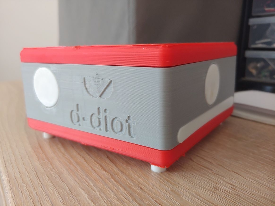
      As a result, the d-diot project is open and free in all its own software parts: for example all the configuration steps, script (oled), hack, tips and tricks are documented in the manual installation section of the wiki.

      Opening the hardware completely in this moment is not so easy as for the software part because, as said above, selling some boards is the only options that i see to keep the project sustainable and self-sufficient from an economical point of view (hosting cost, test new pcb, buy the hardware, etc...).

      Of course opening the hardware could improve the development with the contributes of other people, so I don't exclude this possibility for the future; at the same time sharing some schematics parts is not so dangerous, so to answer to your question about the step-up voltage regulator MT3608, see below:

      0_1559466706427_atmega2560_0-page1.rotated.jpg

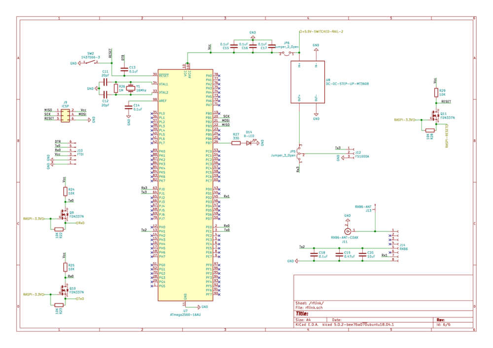
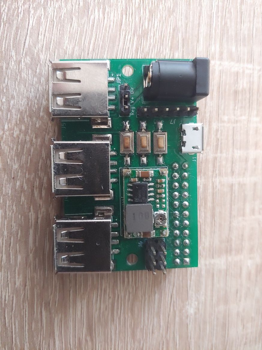
      The scope of the MT3608 is to power the FS1000A radio module (433 MHz transmitter) at 10-12V, to increase the range of the signal. The MT3608 is not strictly necessary because you can power the FS1000A with the RX3 PIN of the ATMega2560, bridging pin 1 and 2 of the jumper 5 (JP5). All is explained here.

      The step-down MP1584 must be set to 1.5V if it is used to power one or more 940 nm IR LED (3W - 700 mA). The details are here, below the schematic:

      0_1559467905993_ir-page1.rotated.jpg

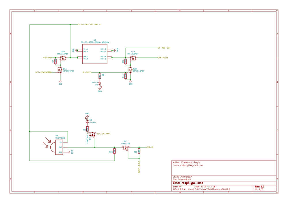
      The ir-pulse rail is connected to the pin 2 (+) of the J4 connector and to the D- pin of the USB port. A single IR LED is connected to the J4 connector, but if you want to increase the coverage of the IR signal you can connect 2 or 3 additional LED with the USB port. Please note that the MP1584 is rated at 3A.

      The V-REG-OUT rail is connected to the D+ pin of the USB port.

      Regarding the power rails, 5V is the main voltage provided by the power supply (+5V-IN in the schematics), while for the 3.3V there are 3 different lines, to not overload the voltage regulator of the Raspberry Pi:

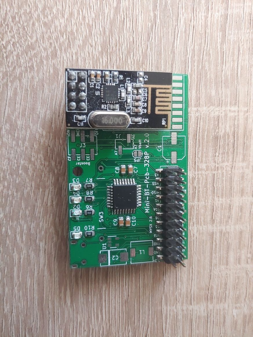
      • Line 1: provided by U2 (AMS1117 and its caps) and dedicated to power only the NRF24L01. In this way we have a voltage as smooth and stable as possible, to avoid problems with sensitive radio module.

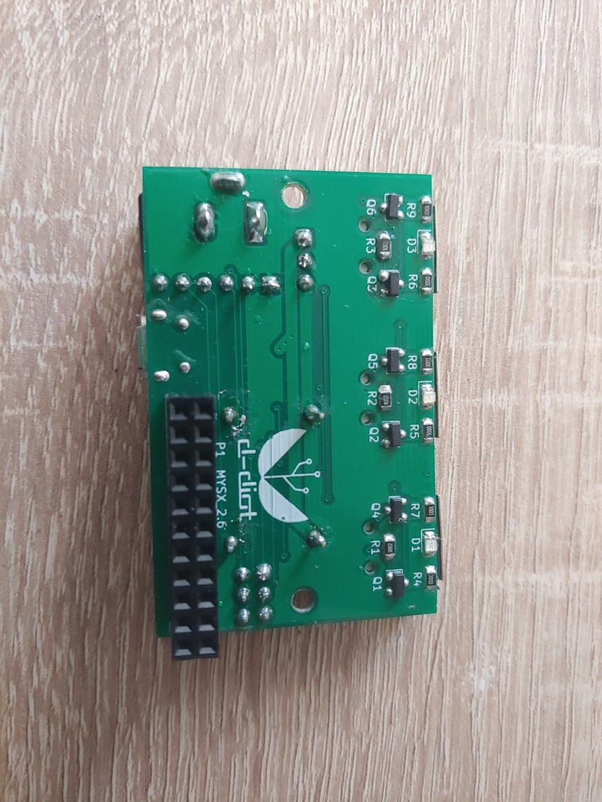
      • Line 2 (RAW): provided by U6 (AMS1117 and its caps) to power the radio activity and power status LEDs

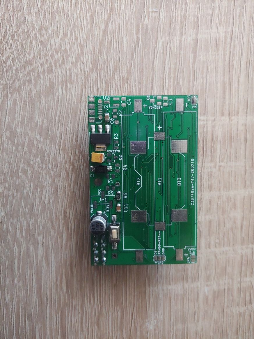
      • Line 3: provided by Raspberry Pi GPIO and used to power the RFM69 radio module.

      posted in My Project
      franz-unix
      franz-unix
    • MYSBootloader and PlatformIO

      Hi,
      Is there someone that use PlatformIO to write the code for MySensors nodes?

      I have discovered it recently and it has some advantages respect to the Arduino IDE, but I have not found, at least in a vanilla installation, the support for Arduino boards with MYSBootloader.

      I have not found anything with a basic google search, so maybe this is the right place to ask.

      posted in Development
      franz-unix
      franz-unix
    • RE: Esp32-cam with pan - Mysensors powered

      @mickey Yes you can drive the motor directly from the esp32-cam module, but with MySensors you can put in deep sleep and wake up the esp32 on demand (pir, timer, etc...) for eample with an automation managed by the controller.

      In fact the esp32-cam, at least with the esphome firmware, is always active and the module become hot after few minutes.
      With an additional controller more power friendly you can turn on the module only when necessary.

      posted in General Discussion
      franz-unix
      franz-unix
    • RE: RF433 Hub for controlling Watts Clever switches

      @homer Glad that it helped!

      But make sure that RFLink supports your Watts Clever smart plug. If you already have an Arduino Mega and an RXB6 receiver at home is quite easy and fast to verify that.

      Another interesting option is that you can couple the Arduino Mega with an ESP8266 and then expose the serial output over Wifi with ser2net (see here) in the ESPEasy firmware.

      This other project goes further and use an ESP8266 to write the serial output of the RFLink to an MQTT server.

      Both solutions add flexibility to the positioning of the RFLink module in your home.

      posted in My Project
      franz-unix
      franz-unix
    • RE: Which battery measurement to use?

      If you go with 2xAA or 2xAAA rechargeable batteries (2.4V) and an Arduino (ATMega328P) without a booster set the BOD level to 1.8V and run your MCU at 1 Mhz.
      With a Vcc of 2.7V and the MUC running at 8 Mhz I have experienced some problem (reset). See here for more details

      posted in Development
      franz-unix
      franz-unix
    • RE: What did you build today (Pictures) ?

      @BearWithBeard ๐Ÿ‘ ๐Ÿ˜ I love the video of the swiss guy!

      posted in General Discussion
      franz-unix
      franz-unix
    • d-diot Gas sensors and RGB lamp

      Hi,

      today I have finished the wiki page of this node that is part of the d-diot project.

      It is a gas sensor (MQ2) based on Arduino Nano and nrf24 radio module with a Neopixel RGB lamp, all in a 3d printable case.

      This how it looks:

      0_1562420572458_DSC_3405.JPG

      If someone is interested in the wiki page are reported all the details for the construction, including firmware, case design files and Kicad project of the GP pcb nano board.

      posted in My Project
      franz-unix
      franz-unix
    • 18650 battery power board

      Hi, to power a sensor or actuator with a 18650 li-ion battery I have designed this pcb based on a tp4056 module and MT3608 booster.
      0_1546261061633_3d-front.jpg
      0_1546261074134_3d-rear.jpg

      Schematic:
      0_1546261091048_18650-pwr-001.jpg

      Main features:

      • Load sharing circuit to safely power the load while charging the battery

      • Boost converter MT3608 (optional) to increase the output voltage. To reduce the size of the board the right part delimited by the vertical white line can be cut out

      • Charging status signaling led (optional)

      • Voltage dividers (optional) to measure Vin - V batt - V boost - V standby. Output available through J4

      • Battery reverse polarity protection through mosfet Q4, excludable through jumper JP3

      • Battery voltage measure point can be selected through jumper JP2

      This board can be used with this one

      I have ordered it (JLCPCB) but yet tested. After that if someone is interested I can share it through openhardware.

      Any suggestion / improvement / comment is well appreciated.

      posted in Hardware
      franz-unix
      franz-unix
    • RE: MySensors 2.3.2 released

      Hi guys, thanks for this release! ๐Ÿ‘ Tested with a Pi 4 and a dual ethernet gateway (RFM69 + NRF24): it works!
      My /boot/config.txt is here.

      posted in Announcements
      franz-unix
      franz-unix
    • RE: What did you build today (Pictures) ?

      @NeverDie Good question. My is too young (2 days) to say something.

      Here a possible solution. See at about 9:50

      posted in General Discussion
      franz-unix
      franz-unix
    • RE: Pir AS 312 with 2 rechargeable AAA battery. Boost needed?

      Hi guys, problem solved ๐Ÿ˜‰

      The high current issue was caused by the damn flyback diode (D7).
      Now the boost converter works as expected and without triggering false positive issue on the PIR (AS312).
      No problem also with the radio module (RFM69@868 Mhz). Not yet tested the board with a NRF24L01 radio module (THT or SMD) but I have both modules, so it is just a matter of time.

      After some testing I have decided to remove Q3, Q4 and Q5 because the boost converter (ME2188C33) when not enabled through the CE PIN (driven by D4 of the ATMega) act as sort of "bypass" for VCC.

      With 2xAAA rechargeable batteries at 2.4V I have had some stability problem with the MCU (reset), but I have solved setting the frequency and the fuses to work at 1 Mhz (with MYSBootloader). Is it normal that an ATMega328 at 8 Mhz is unstable at 2.4V?

      The last thing that I have to change is the circuit of the blu led (D3)... The typical voltage drop of this led is 3.0V, so with 2xAAA batteries and 2.4V the brightness is to low, so the idea is to power it with the 3.3V out of the boost converter, controlling the brightness through an N-Mosfet, driven by PIN D5 of the AtMega.

      The firmware is under testing and is available here

      Below the updated schematics.

      0_1567974516195_output-1.rotated.jpg

      posted in Hardware
      franz-unix
      franz-unix
    • RE: Pir AS 312 with 2 rechargeable AAA battery. Boost needed?

      @scalz I know that you are a beast in the board design ๐Ÿ˜
      Thank you for sharing your experience! ๐Ÿ˜‰

      Newer MCU, like NRF52 will be also my next step, but for the moment I feel more comfortable with the well known and easy to use ATMega328P.

      I agree with you, the range and the reliability of the RFM69 is by far better than NRF24.

      posted in Hardware
      franz-unix
      franz-unix
    • RE: Pir AS 312 with 2 rechargeable AAA battery. Boost needed?

      And... the 3d printed case for the board V.1.0
      Some adjustment in the tolerances and print settings are required, but the final results may not change so much.
      0_1569154773123_20190922_140443.jpg
      0_1569154788879_20190922_140453.jpg
      0_1569154800318_20190922_140629.jpg
      0_1569154811197_20190922_140643.jpg

      The case for the board V.2.0 will be similar, only the position of the LED will change.

      posted in Hardware
      franz-unix
      franz-unix
    • RE: multiple hardware radio sensor network

      @blom Hi, if you want to run two gateway on the raspberry GPIO, it is possible but it requires some configuration steps.

      You can find some info here in the forum or you can see here how I have done it for the d-diot board (check basic system and MySensors pages).

      I have used an RFM69 radio module in combination with Nrf24, but it should work also for an rfm95, if the wiring is the same.

      posted in Hardware
      franz-unix
      franz-unix
    • RE: Pir AS 312 with 2 rechargeable AAA battery. Boost needed?

      @DenisJ : Glad to know that this work has been useful for you in some way. ๐Ÿ‘

      Regarding the AAA battery holder, the footprints on the PCB are for a Keystone 5204 (negative) and Keystone 5226 (positive) contacts.

      I have purchased them on ebay; unfortunately the item that I have purchased is not more available, but this one appears to me like the same thing.

      posted in Hardware
      franz-unix
      franz-unix
    • RE: Pir AS 312 with 2 rechargeable AAA battery. Boost needed?

      @DenisJ the link is broken, so I have not seen the contacts that you have bought, but if they are just a little bit smaller and they can fit the hole on the pcb, they should be OK.

      posted in Hardware
      franz-unix
      franz-unix