@DenisJ the link is broken, so I have not seen the contacts that you have bought, but if they are just a little bit smaller and they can fit the hole on the pcb, they should be OK.
franz-unix
@franz-unix
Posts
-
Pir AS 312 with 2 rechargeable AAA battery. Boost needed? -
Pir AS 312 with 2 rechargeable AAA battery. Boost needed?@DenisJ : Glad to know that this work has been useful for you in some way. :+1:
Regarding the AAA battery holder, the footprints on the PCB are for a Keystone 5204 (negative) and Keystone 5226 (positive) contacts.
I have purchased them on ebay; unfortunately the item that I have purchased is not more available, but this one appears to me like the same thing.
-
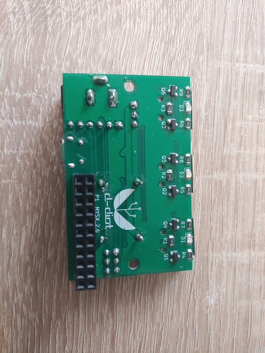
What did you build today (Pictures) ?Hi guys,
my last creation: the d-diot hub v.3.0
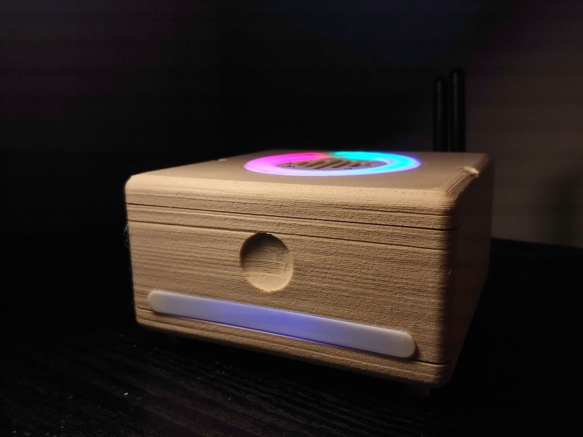
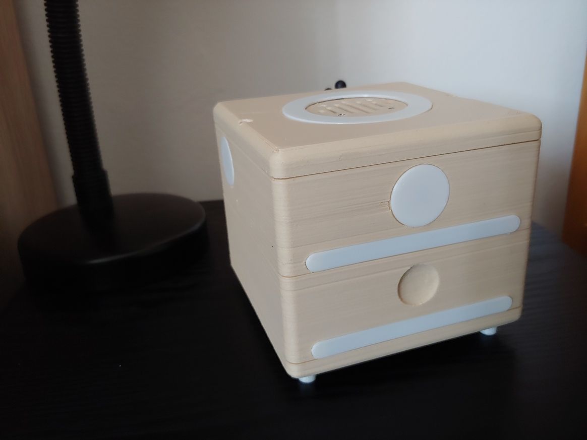
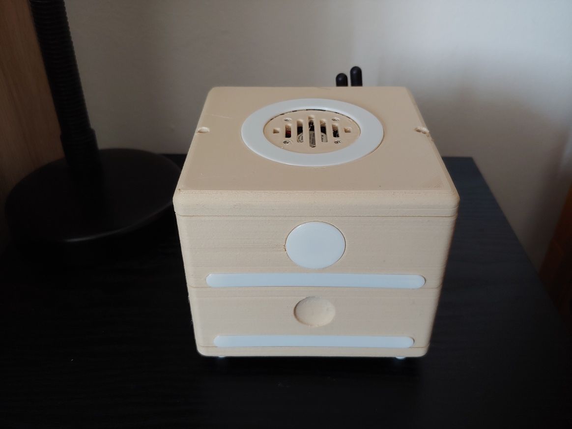
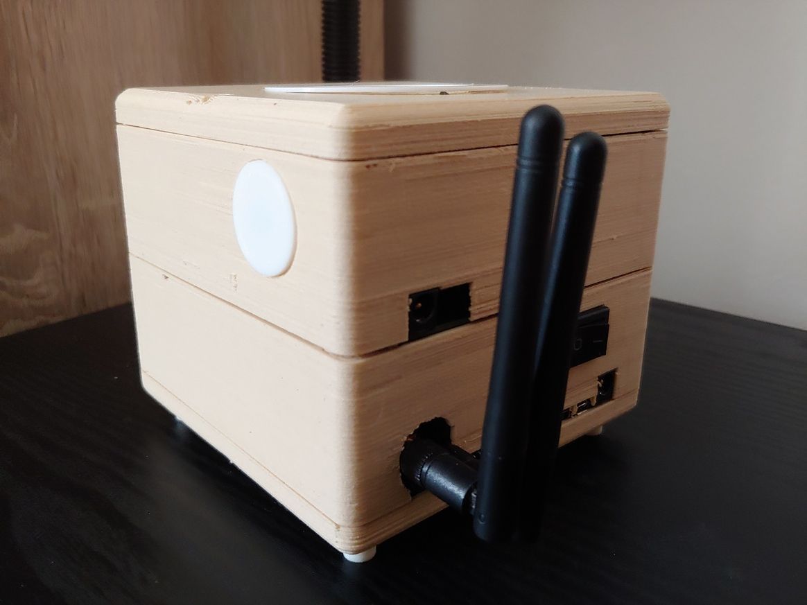
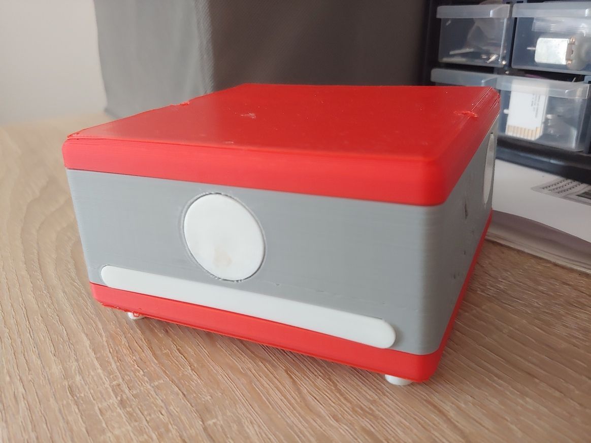
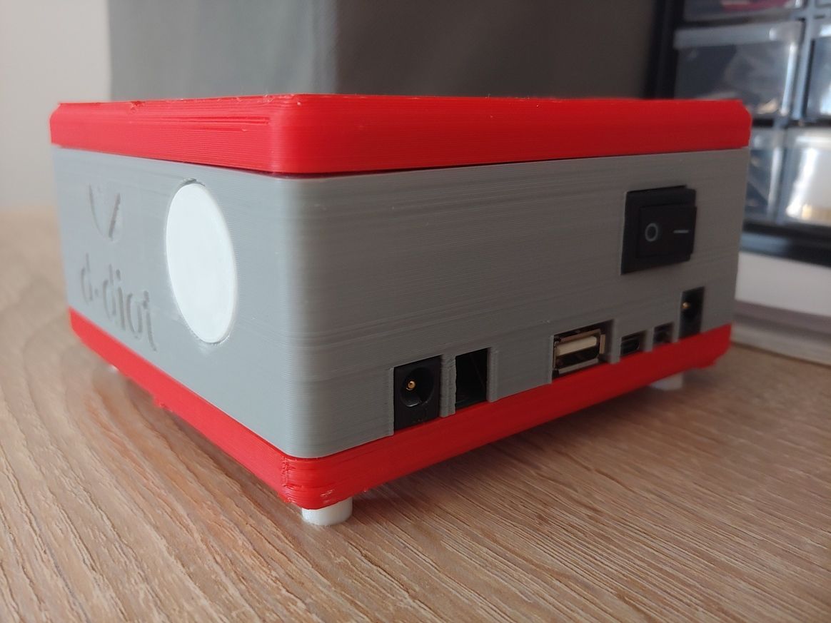
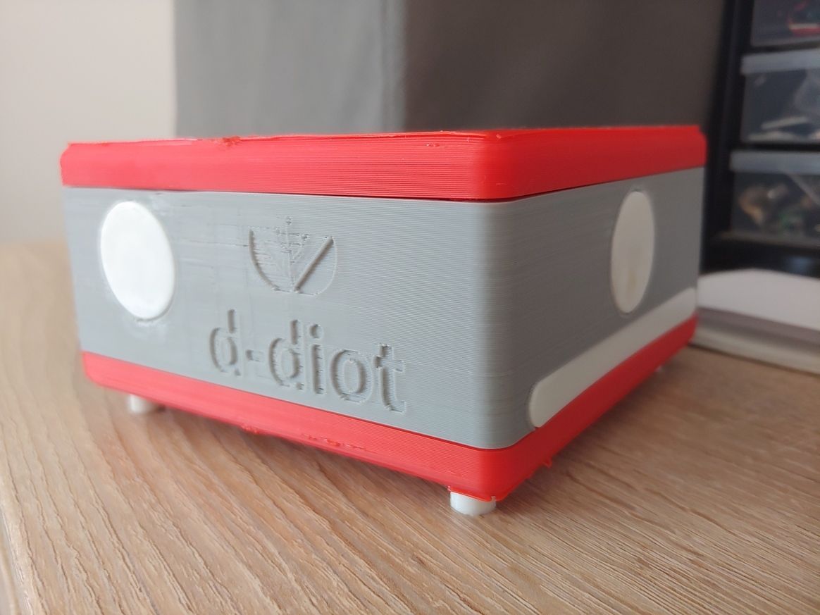
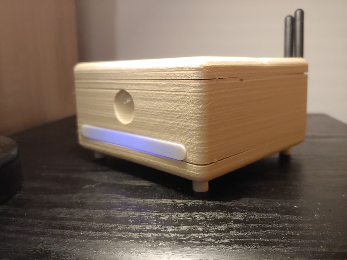
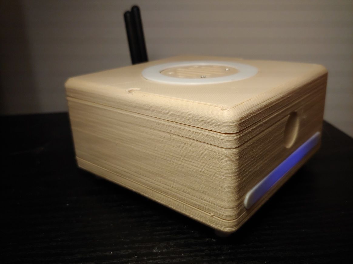
The hub A (wood) is a dual MySensors gateway (RFM69 and NRF24) based on two ESP8266 modules and a BLE gateway + RGB controller thanks to an ESP32 module and ESPHome firmware.
The hub B (grey and red) is an IR gateway and RC 433 Mhz gateway based on ESP32 modules with an ESPHome firmware. The hub B has also an integrated step-up and step-down voltage regulator based on Arduino Nano.
To allow the maximum flexibility in placement inside the house, each module can be build as a stand-alone piece of hardware or combined in a single device (see pictures).
The hub is meant to be used with Home Assistant, the case is 3d printable and as usual, if someone is interested, there is a dedicated wiki page with all the details and the build instructions.
-
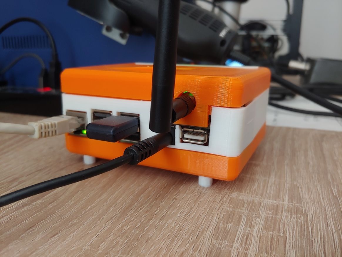
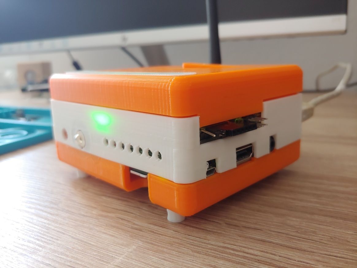
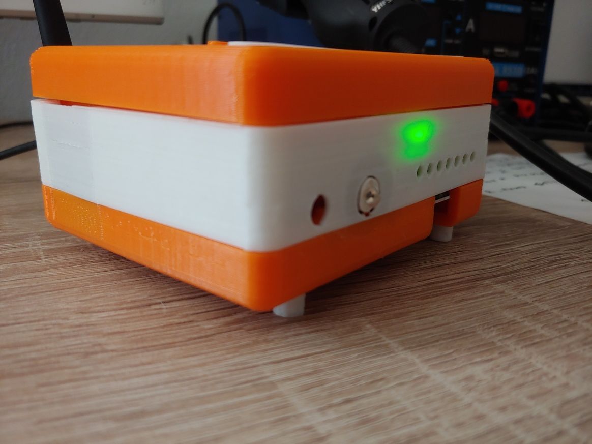
What did you build today (Pictures) ?Hi guys,
this is my last node. A 3d printable smart USB power hub.
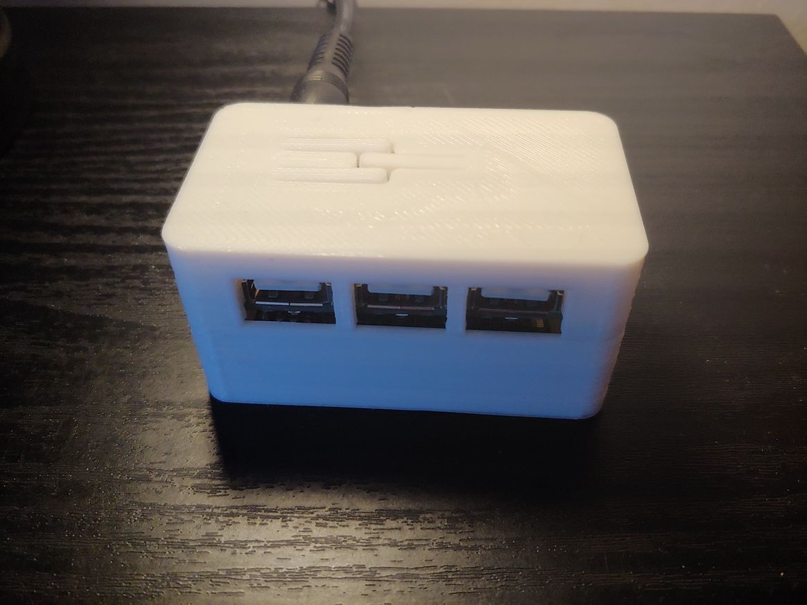
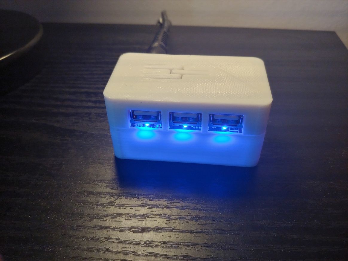
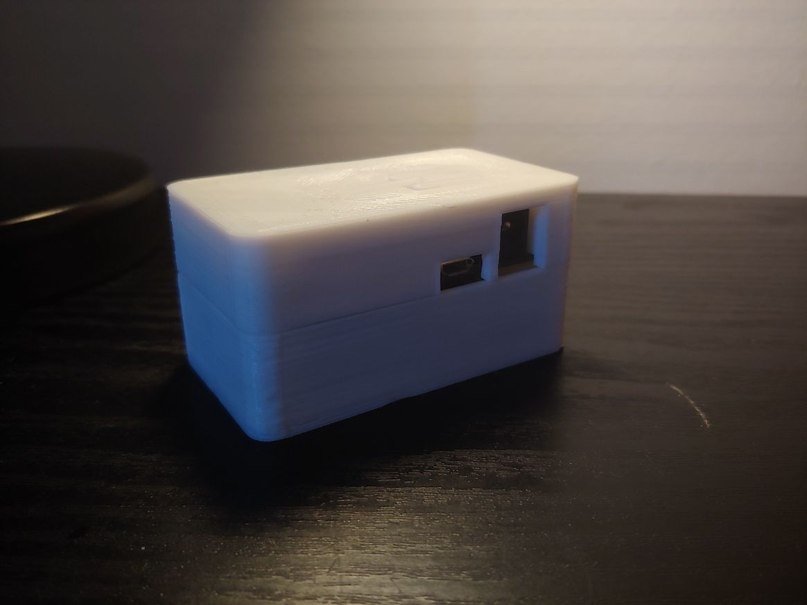
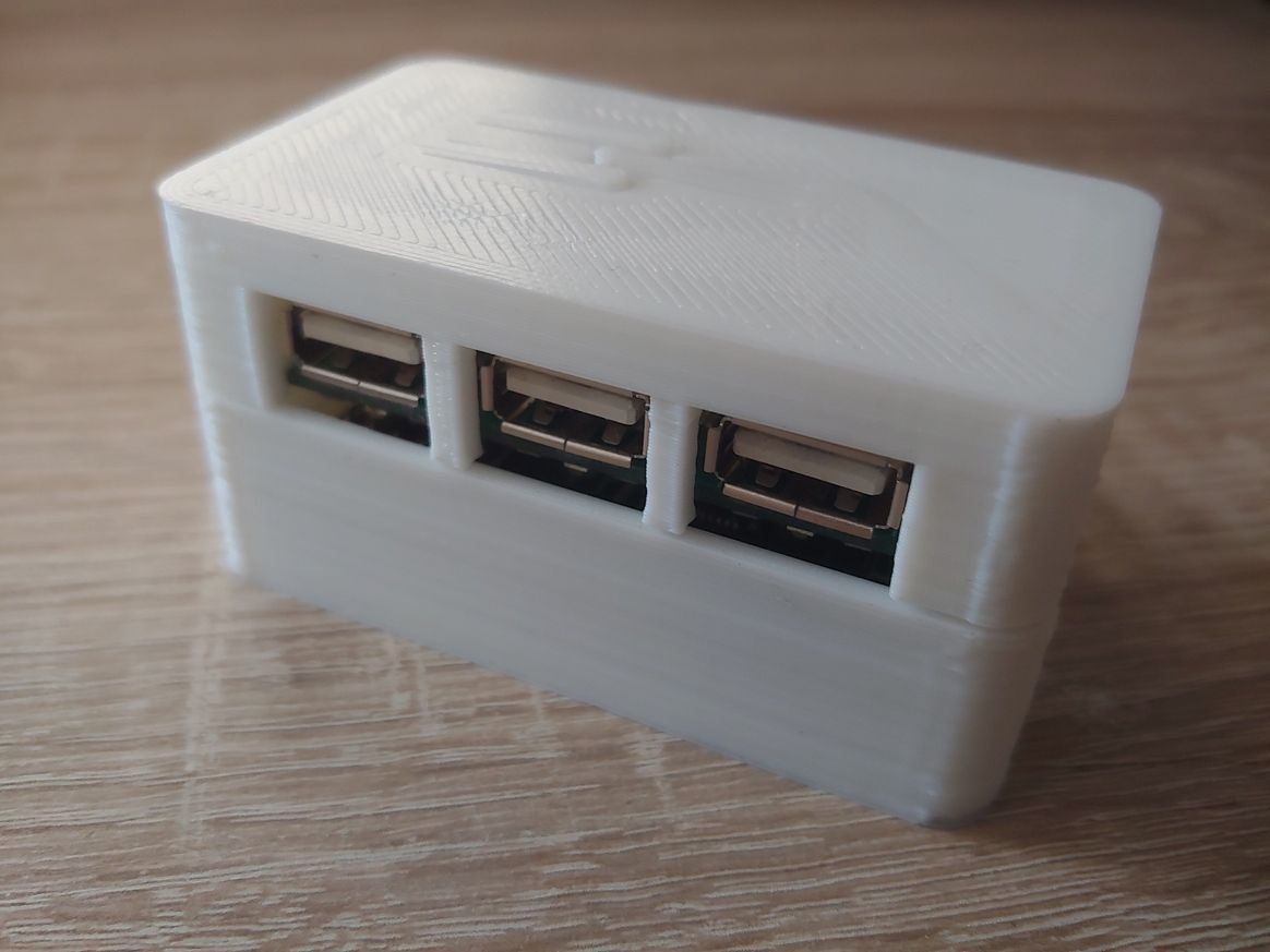
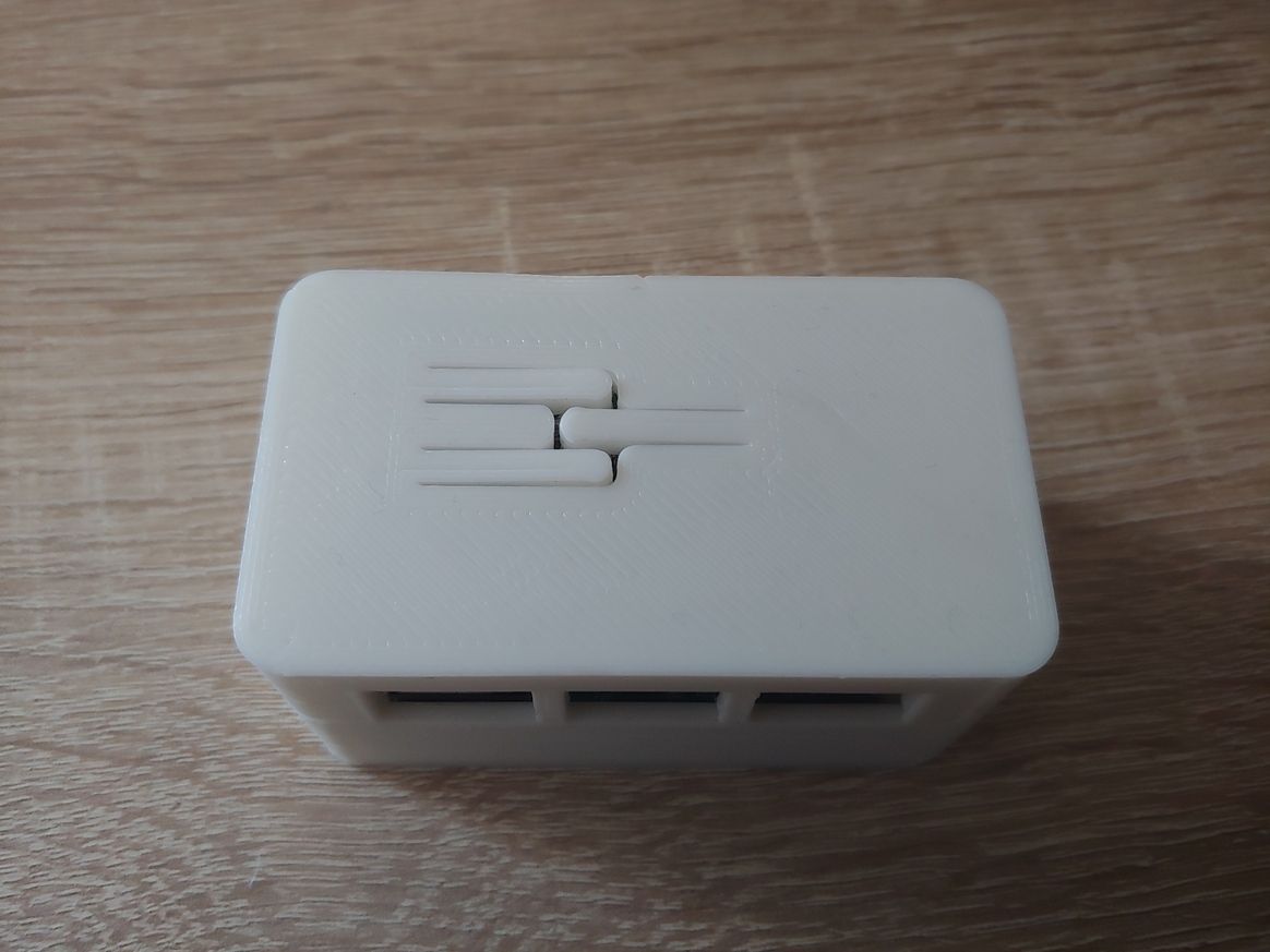
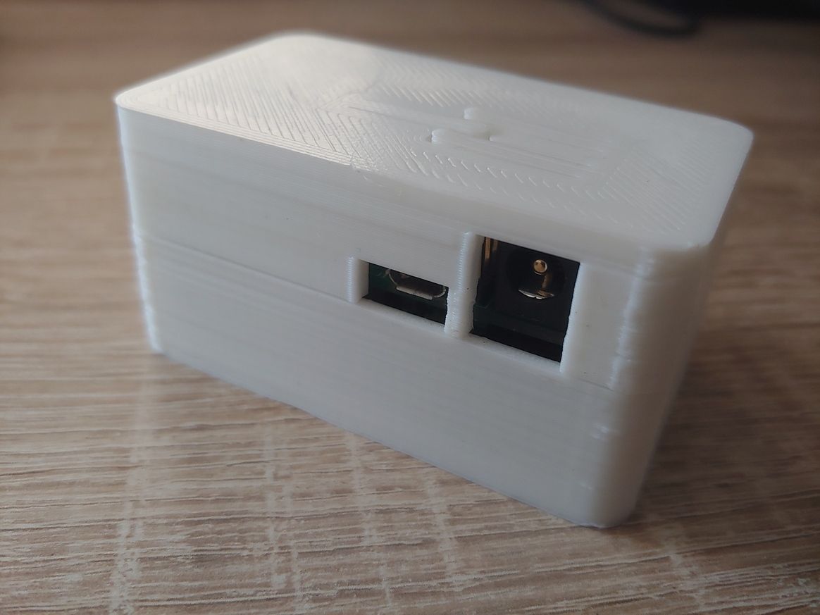
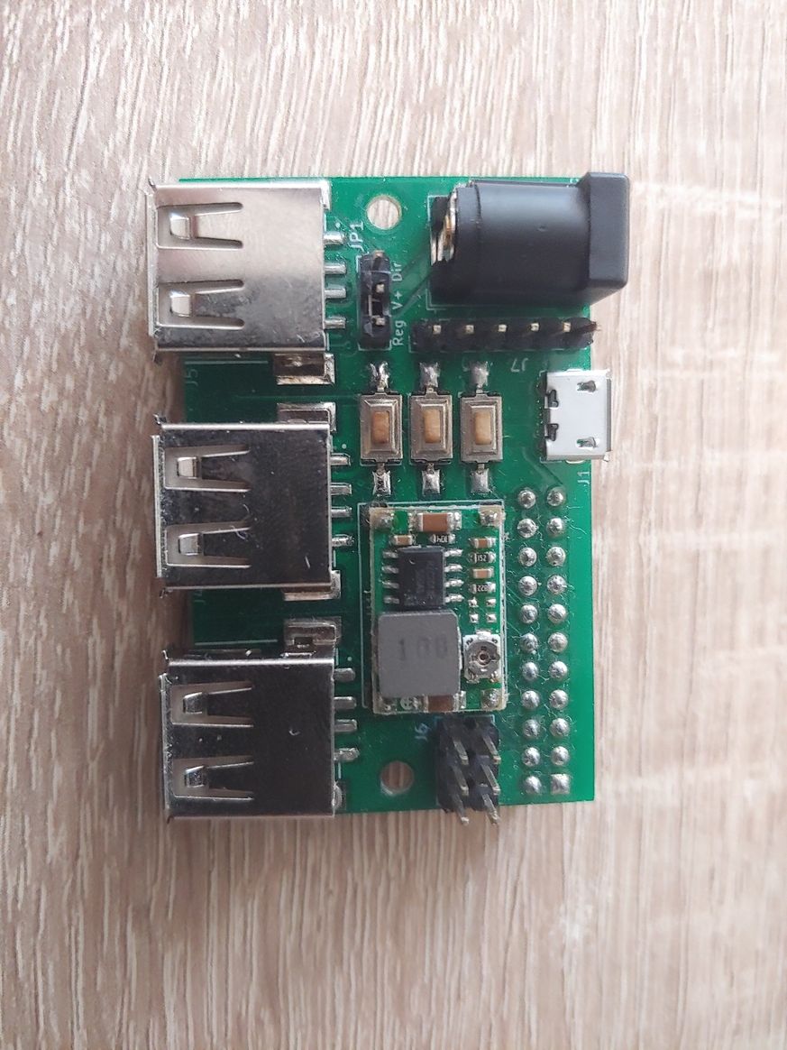
If someone is interested, here all the details.
-
Started with MySensors and about to give up (some feedback)Interesting topic!
I agree, the amount of time required to learn how to do the things is quite high and after a lot of research you will find that other people have had the same issue... so in the end you have just reinvented the wheel!In any case I think that MySensors is a very good project and probably underrated respect to how good and useful it is for a maker that wants to build its own domotic sensor and actuators.
For the reasons above (and others), some times ago I have started the d-diot project:
-
The hub (Raspberry Pi + d-diot board) implements, among the other things, two MySensors gateway (RFM69 868 Mhz + NRF24L01). All the software configuration steps are well documented in the dedicated section of the wiki.
-
In general the software part is easy because all is preconfigured in the d-diot image. Just burn the iso image to an SD card and you will have Home Assistant and MySensors working and ready to go.
-
3d printable sensors and actuators and the relative PCBs and firmware are part of the project. All parts (hardware, firmware, 3d printable case) are open source
-
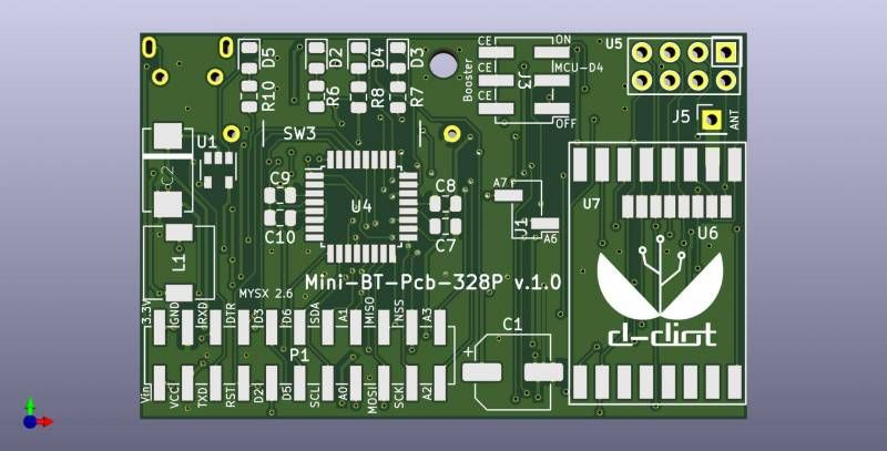
In the wiki you will find the detailed build instructions (with pictures) for each device, so @mhkid and @Psilin maybe here you can find some useful information or a at least a good starting point for your nodes. In particular the Mini-BT-Pcb-328P is a general purpose and flexible board that could be useful for a lot of small (battery or USB powered) RFM69 or NRF24L01 nodes.
Now I'm in contact with PCBway, a PCB manufacturer that offers also soldering service, so If there are enough people interested, I think that it is possible to start thinking about the possibility to start a small production of some boards, maybe already assembled. In my opinion this will be helpful for other people.
Let me know... maybe we can start something :+1:
-
-
Coronavirus (way, way, off topic)@NeverDie a sodium hypochlorite solution is what is commonly known as bleach. Probably is more convenient to buy it rather than produce them.
Just to give you an idea, below a picture of a famous bleach commercialized in Italy... Maybe you have the same brand in your country

Your question about the concentration and efficacy is interesting.
-
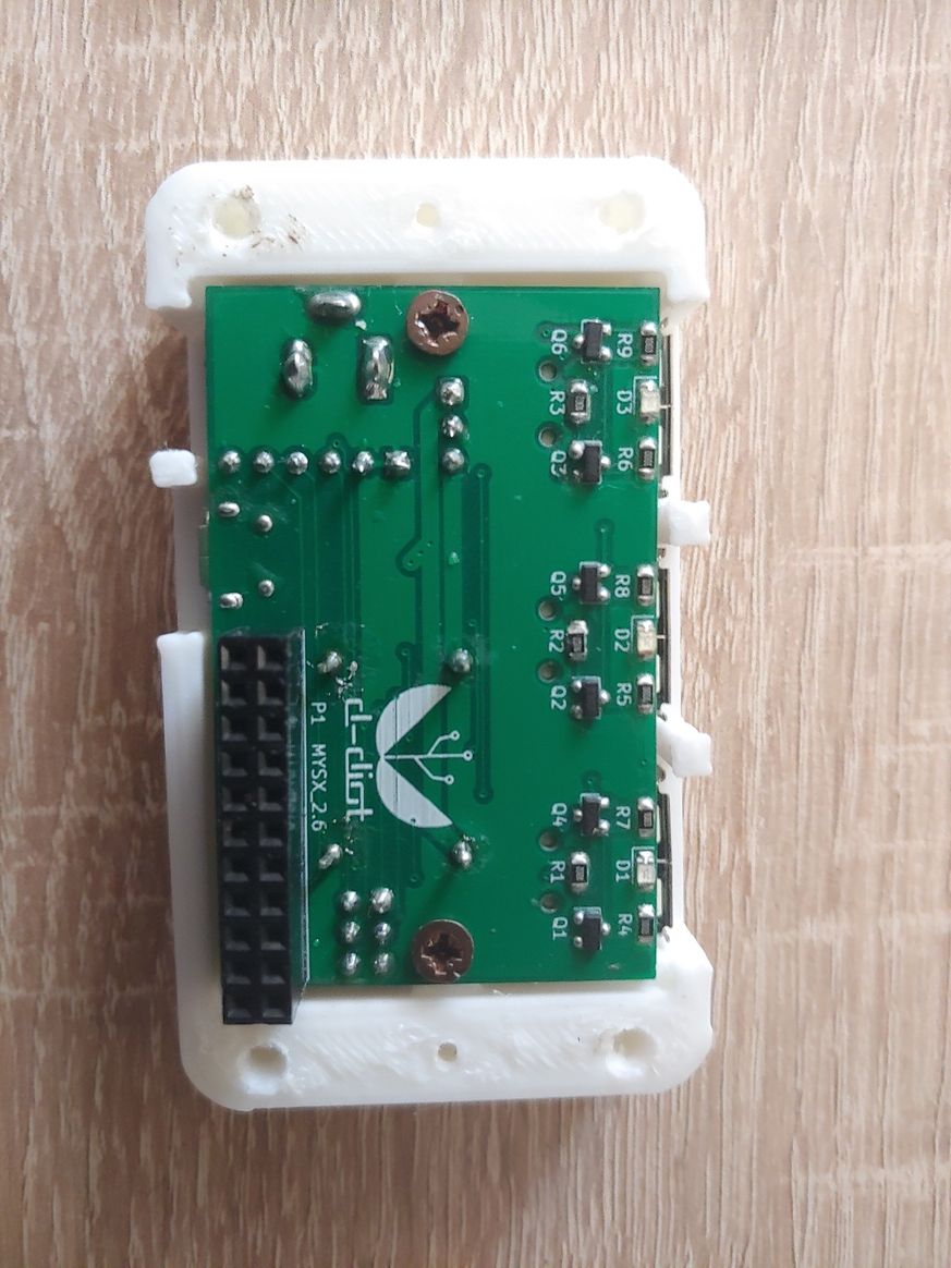
What did you build today (Pictures) ?Hi guys,
today I have finished the 3d printable case of the d-diot hub.
The hub basically is a Raspberry Pi 3 with the d-diot board (see this topic) that offers the following functionalities:
-
IR Gateway (blaster and receiver) to control every device that has a dummy infrared remote.
-
433 Mhz Gateway with the RFLink firmware running on the on-board ATMega2560 microcontroller
-
Dual MySensors Gateway: NRF24 (2.4 Ghz) and RFM69 (868 Mhz).
-
Latch circuit to power-on and safely power-off your Pi with a simple button press.
-
SSD1306 I2C Oled display controllable in Home Assistant
-
Radio activity LEDs for IR and Mysensors gateways
-
Nice and powerful web interface thanks to Home Assistant
-
Easy setup and configuration with the d-diot image
If someone is interested, here the detailed build instructions.
-
-
What did you build today (Pictures) ?@BearWithBeard :+1: :grin: I love the video of the swiss guy!
-
What did you build today (Pictures) ? -
What did you build today (Pictures) ?Hi, finished two nodes based on the same multi-purpose battery powered pcb (all the documentation here)
One is a door / window sensor based on a Reed switch.
If someone is interested, the dedicated wiki page contains the detailed build instructions.
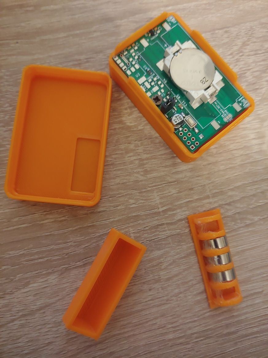
The other is a soil moisture sensor.
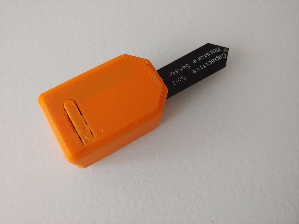
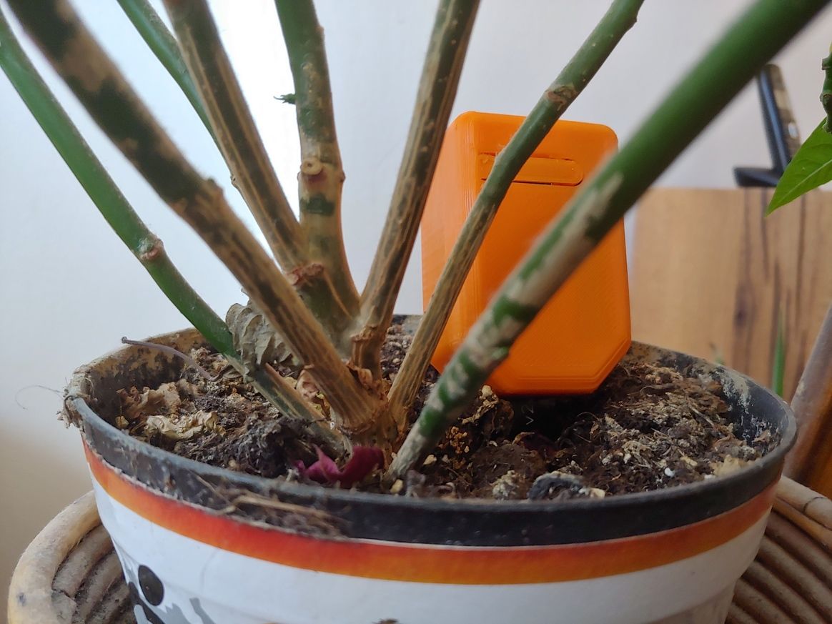
For this one, the wiki page is here.
Happy Easter, even if at home!
-
Small multifunctional battery powered (AAA and CR2032) pcb (NRF24 + RFM69)@skywatch Thnaks! :+1:
The main goal of this board is to offer a simple way to build any kind (RFM69 and NRF24 support, MYSX connector) of compact battery powered node.
Today I have finished the first node based on this board: a door window sensor (reed switch).

If someone is interested, here the detailed build instructions.
The next node based on this board will be a soil moisture sensor!
-
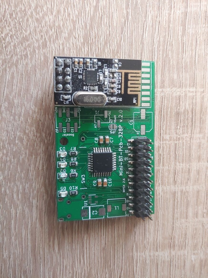
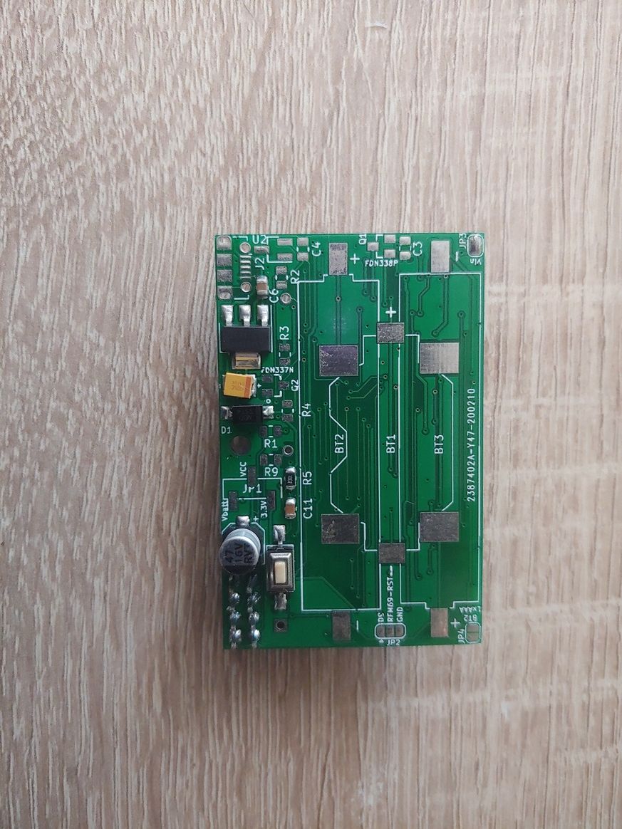
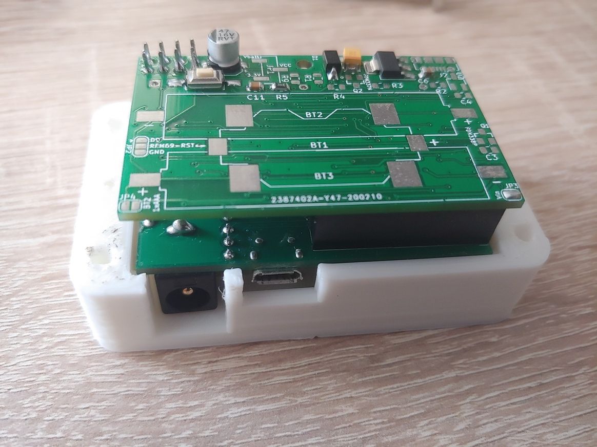
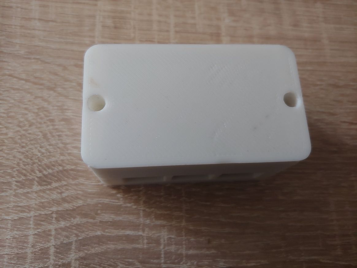
Small multifunctional battery powered (AAA and CR2032) pcb (NRF24 + RFM69)Hi guys,
in order to facilitate the development of any kind of battery powered sensors (or actuators), I have designed this small pcb that can be easily placed in a 3d printable case

The main features are:
-
Small dimensions: 55 x 35 mm
-
Multiple power options: 2 x AAA batteries or 1xAAA battery (Rechargeable or Alkaline), 1 x CR2032 battery, standard cellphone charger at 5V through the micro USB port or through Vin and GND pin of the MYSX connector
-
Reverse polarity protection (Mosfet Q1) to prevent damages in case of wrong batteries insertion.
Boost converter (ME2188C33) to increase the battery voltage to 3.3V when necessary -
LEDs for radio traffic and low batteries signaling. All configurable in the firmware.
-
Multiple radio module supported: NRF24L01 (SMD and THT) and RFM69.
-
Footprint for a reed switch
-
MYSX connector v.2.6
-
Support for ATSHA204 chip (security and signing)
Mounting hole for a M2.5 screw
Probably in this days the ATMega-328P is a sort of "old" technology but for simple battery powered devices it remains a good option, also for its easy of use.
If someone is interested, all the informations and the links to technical files (kicad project, gerber, schematics, firmware, etc) are in the dedicated wiki page of the d-diot project.
-
-
MySensors 2.3.2 releasedHi guys, thanks for this release! :+1: Tested with a Pi 4 and a dual ethernet gateway (RFM69 + NRF24): it works!
My /boot/config.txt is here. -
Printing enclosures with SLA printers.Here a guide with video... very nice:+1: ! Probably a dirty job, but feasible in a garage and this technique could be useful when you have to make multiple copies of the same object.
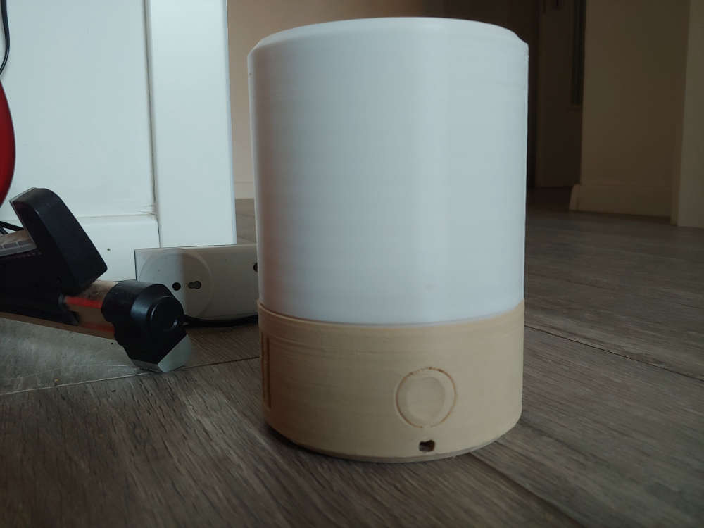
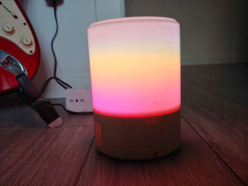
@berkseo: thanks, I'm quite happy with the final result. I will publish the build instructions and all the related stuff of the mood lamp in the d-diot website, hopefully before the end of the year. It is based on an ESP8266 (with a custom PCB) and the firmware is generated with ESPHOME, so MySensors is not involved.
For the base of the lamp, which is printed with a wood filament, I have had to change the nozzle of my printer from 0.4 to 0.6 mm. -
Printing enclosures with SLA printers.@nca78 :+1: thanks for the info! I have seen that the Anycubic resin is available also in big online stores like Amazon, so fast delivery time guaranteed.
@NeverDie: Unfortunately the fragmentation is the dark side of the moon of the open source world, but in my opinion the quality of some project here is really awesome and above the average, so it is a shame that they don't have the adequate visibility. In addition in this last months some big pcb manufacturers like JLPCB have included in their offer an assembly service, so, with the adequate visibility and documentation, the entry barrier for new users in the DIY home autmation could be not so high.
@berkseo The "marble" case is very cool! The filament is easy to print or requires some special parameters? For example in this days I'm fighting with a wood filament, below the results
-
Printing enclosures with SLA printers.@nca78 yes I know that the resin is toxic and unfortunatly another drawback is that you have to wash (with IPA) and cure your parts after printing. For sure not so easy and "safe" like a normal FDM.
But guys... There are a lot of interesting finished projects (pcb+case+firmware), what about a dedicated section and a standard way to collect and present them, maybe with detailed build instrunctions?
This may be helpful for new users but also for more experienced people that have to not reinvent the wheel every time.For example I have tried something like this with my multisensor and Gas sensor.
-
Printing enclosures with SLA printers.@berkseo the final result of your SLA printed part is impressive. In the picture it appears smooth like a part obtained with injection molding.
Probably for small electronic enclosures a SLA printer is better than a FDM. It's Christmas time... I have to consider the idea to buy one😜
-
What did you build today (Pictures) ?Amazing! 😃
The case is 3d printable?
-
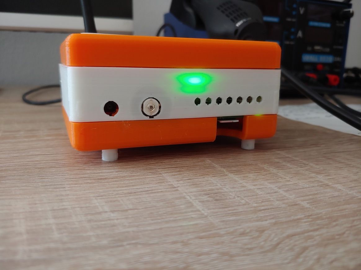
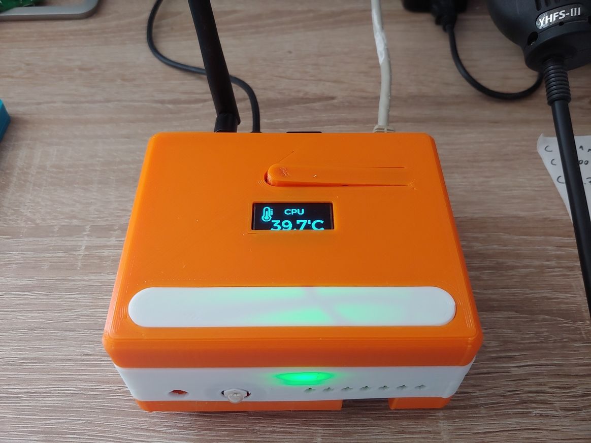
Pir AS 312 with 2 rechargeable AAA battery. Boost needed?Hi guys, project finished! Now the led are under the Fresnel lens, so the design of the case is more clean (WAF +10 :sunglasses: ).
The final result:
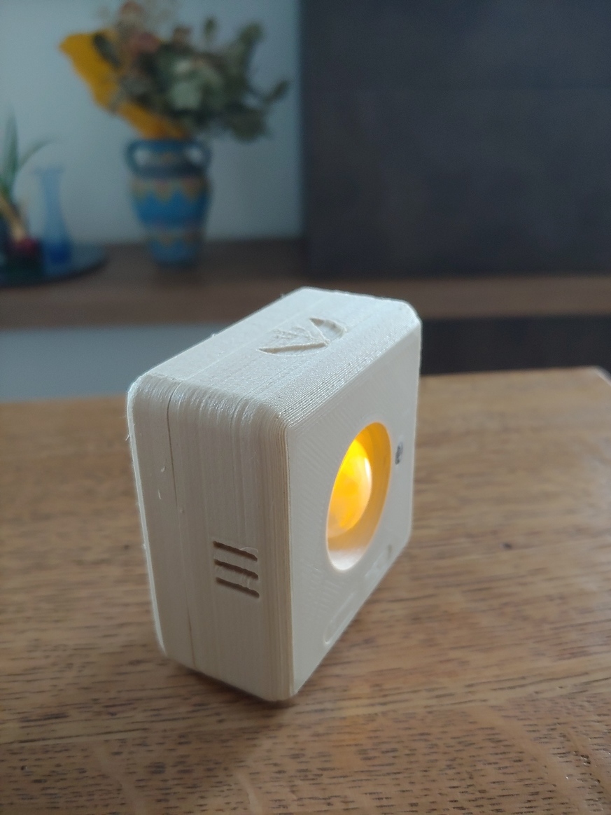
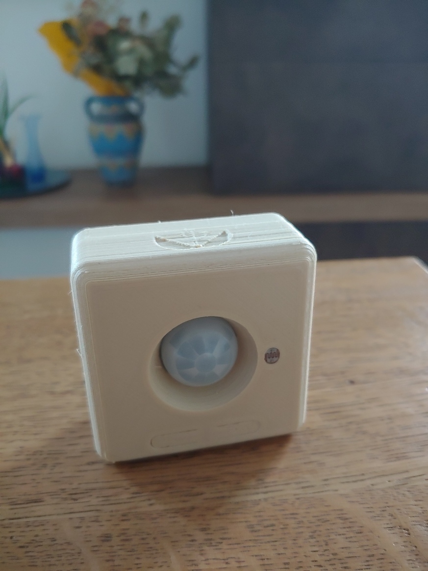

With 2 x AAA batteries and the RFM69 radio module the node works very well and the total cost of the parts is about 10€.
If someone is interested, here a detailed build guide, with the links to all the parts of the project (3d model of the case, Kicad project, gerber files, BOM, firmware).
-
💬 Building a Raspberry Pi GatewayHi, if someone needs more info (debug, log, etc...) I'm here.
I can perform tests on Rpi 3 and Rpi 4 (Raspbian Buster) with NRF24 and RFM69 radio modules and then report the results. Not so much but maybe this can help the development.