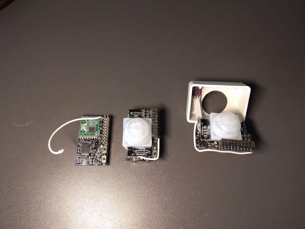
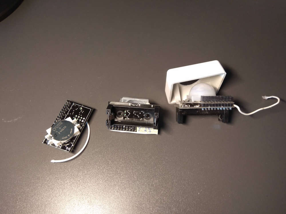
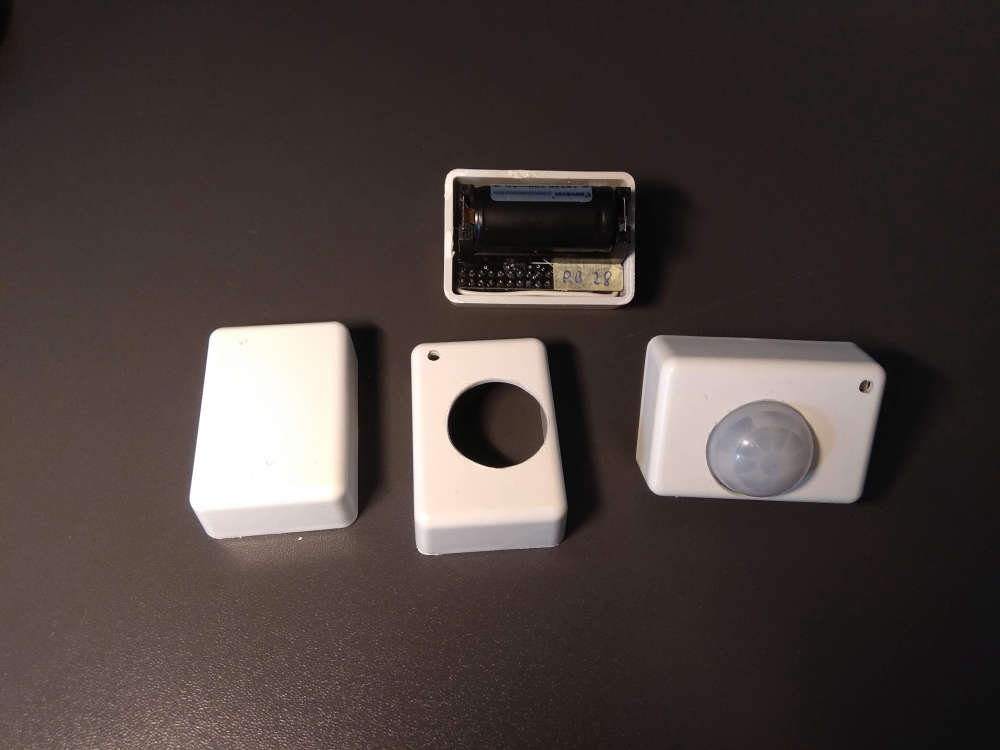
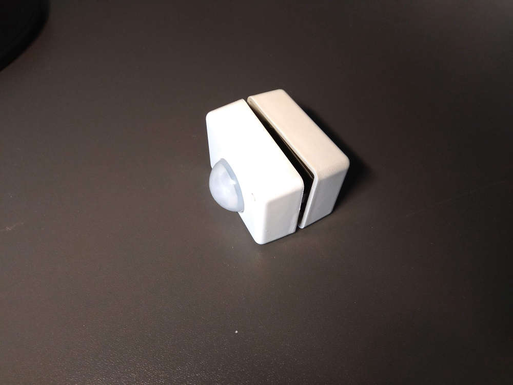
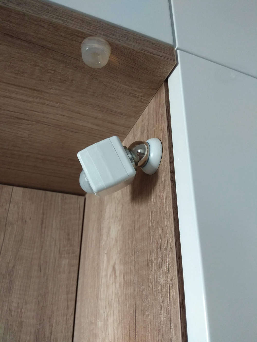
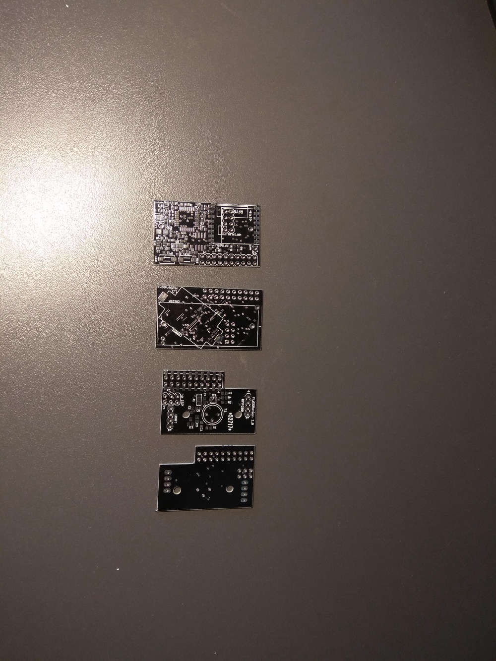
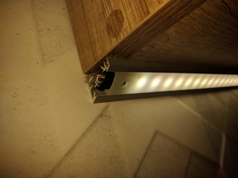
So I finally finished my motion sensor project and it works
It will be published on OpenHardware.io soon
So I finally finished my motion sensor project and it works
It will be published on OpenHardware.io soon
I can now confirm that the apds 9930 module works without any issues. no steam problem so far and the module is located next to the stove. Here are some pictures
HAHA, You can always get a new wife with lower W.A.T (Wife Acceptance Treshold)
@crankycoder use 3v ldo istead of 3.3v ldo. Evereything will work at 3v without problems and you get almos full battery capacity.
So today I created a simple python script to bridge serial gateway with mqtt bus on my RPI:
https://github.com/mczerski/MySensorsSerial2MQTT
This is because I already use spi for nrf24 module mounted on a custom pcb so there is no room for another spi device.
Hi all, I just wan't to share with You my idea about controlling bi-stable solenoids (let it be valves or latching relay, doesn't matter). And I wonder why nowbody considering this solution. I'm talking about this kind of circuit http://www.avrfreaks.net/sites/default/files/Latching relay driver.jpg. And those two transistors that have to be controlled with two pins may be replaced with a push-pull driver like L293 (or L203DD which has built-in clamping diodes) which can be cotrolled with just one pin (HIGH - open; LOW - closed). This L293 will make the hardware interface the same as with monostable relays.
So pros are:
Cons are:
great news with the new nrf modules there is no more range problem for the gatewane i use nrf24l01+pa+lna and for the sensor node nrf24l01+. now from every place in my small flat the connection is perfect
I run mysgw with gdb and for me it segfaults when trying to access gpio:
(gdb) run
Starting program: /usr/local/bin/mysgw
[Thread debugging using libthread_db enabled]
Using host libthread_db library "/lib/arm-linux-gnueabihf/libthread_db.so.1".
Sep 29 13:04:51 INFO Starting gateway...
Sep 29 13:04:51 INFO Protocol version - 2.3.0
Sep 29 13:04:51 DEBUG MCO:BGN:INIT GW,CP=RPNGL---,VER=2.3.0
Sep 29 13:04:51 DEBUG TSF:LRT:OK
Sep 29 13:04:51 DEBUG TSM:INIT
Sep 29 13:04:51 DEBUG TSF:WUR:MS=0
Program received signal SIGSEGV, Segmentation fault.
bcm2835_peri_read (paddr=0x7) at drivers/BCM/bcm2835.c:123
123 ret = *paddr;
(gdb) bt
#0 bcm2835_peri_read (paddr=0x7) at drivers/BCM/bcm2835.c:123
#1 bcm2835_st_read () at drivers/BCM/bcm2835.c:1126
#2 bcm2835_delayMicroseconds (micros=1) at drivers/BCM/bcm2835.c:449
#3 0x0002ce5c in BCMClass::digitalWrite (this=<optimized out>, gpio=<optimized out>, value=<optimized out>) at drivers/BCM/BCM.cpp:62
#4 0x0002d7ac in RPiClass::digitalWrite (this=<optimized out>, physPin=physPin@entry=24 '\030', value=value@entry=1 '\001') at drivers/BCM/RPi.cpp:56
#5 0x0001c22c in hwDigitalWrite (value=1 '\001', pin=24 '\030') at ./hal/architecture/Linux/MyHwLinuxGeneric.cpp:158
#6 RFM69_initialise (frequencyHz=868000000) at ./drivers/RFM69/new/RFM69_new.cpp:206
#7 0x00020da4 in transportInit () at ./hal/transport/RFM69/MyTransportRFM69.cpp:26
#8 stInitUpdate () at ./core/MyTransport.cpp:100
#9 0x000258a4 in transportUpdateSM () at ./core/MyTransport.cpp:384
#10 transportProcess () at ./core/MyTransport.cpp:464
#11 transportWaitUntilReady (waitingMS=0) at ./core/MyTransport.cpp:453
#12 _begin () at ./core/MySensorsCore.cpp:155
#13 0x00012f2c in main (argc=1, argv=0x7efff4c4) at ./hal/architecture/Linux/MyMainLinuxGeneric.cpp:447
On RPI platform the gpio kernel driver is not used, instead gpio is accessed with mmap :(. When I forced the build to use gpio kernel driver all works without problem when running as non root. So maybe the solution should be to add configure option for rpi to use gpio kernel driver ?
@Nca78 I'm also using 9930 and it is quite insensitive to transparent stuff, even partly transparent plastic cover. I am now finishing my kitchen and plan to put the sensor behind the milky plasic cover of the led aluminium profile, then drill the small hole for the ir diodes and cover the hole with fully transparent plastic. I made the prototype like this and it is working very well, but didn't test with the steam yet ...
no You can't, but You do not need an oscillator for atmega if You do not need precise timings, just use atmegas internal oscillator.
@pjr version is almost correct, it would be correct without references, so skip '&' symbol and it should work
@titvs I also would recommend to go for rfm69. I had exactly same problems as you, and tried a lot of differenr nrf24 modules and still couldnt get a descent result. As soon as i switched to rfm69 all my problems disappeared after all i spent more money on nrf24 modules than i would spend on rfm69 if i would start with them. Use nrf24 to rfm69 adapter board for easy transition.
so I went for similar ldo that I was able to get quickly TPS782, it is very similar to MCP1711. And I just made a test board with an atmega328p, nrf24l01 and voltage divider for the battery voltage measurement (1.1Mohm). In sleep mode it draws 7uA Think it is a pretty good result
I had similar problems. What is happening is the rfm69 drivers is checking the rssi value before sending anything. If rssi is below some treshold the mesage is sent, and if not the driver waits 500ms and then it sends the message regardless of the rssi value. When message is send, the driver waits only 200ms for the ack, so if other end has high rssi value the ack is not received on time. So the problem is high rssi value before sending. In my case it was due to poor power supply so i would recommend powering the rfm module from separate low noise ldo regulator.
@heinzv as i wrote before there are other transports than just nrf. There is wired rs485, lora rfm95, and for those like me that live in a bunker the 2.4ghz band has very poor range so the 868mhz rfm69 is the solution. So there is plenty reason to not use nrf5 and for those cases stm32 is quite a good choice.
@magnusf It is important to know that the battery voltage is non linear in respect to how much juice left. Just search for "battery discharge curve" to see how much it depends on battery type, current and temperature. So calculating the percentage is actually meaningless unless You exactly know how much current your board sucks at what temperature and what type of battery You use.
don't know about HA, but I'm running mysensors mqtt gateway with openhab on rpi 3 (and Mosquitto as a broker), works without any problems.
depends on the sensors, some works with 3v some does not and they require boost converter. You will find everything in sensor datasheet.
@mfalkvidd said:
@rozpruwacz as mentioned on the list linked from the page I mentioned, OpenHab is a controller.
However, I think I read somewhere that it is not possible to hand out node IDs through mqtt, so you'll need to either use a different type of gateway or continue assigning node IDs manually. Either way is fine.
ok, understand, i can assign node id's staticaly, no problem.
As for the power, the capacitor on the nrf module has proven, over and over again, to be insufficient. That is why the radio connection instructions and the troubleshooting instructions mention adding an extra capacitor. It is not about the amount of power, it is about the
stability of the power.
so the additional 10uF should be sufficient, so what else could degrade the range ?
btw. a did this trick (https://www.youtube.com/watch?v=NpMnauHeR7Y) and it helped a lot, but it gets a little big
The heat sounds strange. I haven't seen that in any of my modules. Maybe the vendor sent defect modules?
i will try to measure the current.
and what about the issue with the communication not recovering from the blackout, e.g. if the mysGateway goes down the node would never recover unless i will recycle the power.
@diogoc AFAIK no. I'm using mqtt with MyController (not Myscontroller) and it works great.
maybe your power supply is not able to provide enough current ? How you power it ? Do you use NRF24L01 with amplifier ? If yes than connecting nrf to 3.3v rail from the arduino mey be not a good idea, it can provide maximum of 150mA.
I would thing about the design, is it realy needed to show currently selected scene on the scene controller ? This makes the information redundant and therefore more prone to such errors.
i found the solution for not connection not recovering from the blackout (https://forum.mysensors.org/topic/4593/battery-sensor-and-re-connecting-to-gateway/2)
the sketch i'm using is "sleeping" between button presses and the transport layer have no time to reestablish connection. adding the wait statement to the sketch solves the problem.
@andrew I see that You put the nrf module between two pcbs. Do You have issues with reception ? Because the boards may act as a shielding.
Oh, and my suspicion is that the gateway send much more packets when node is not responding which make it consume more power and this couses the voltage to drop and restarts the gateway.
yeah, now it makes perfect sense. i saw how to configure leds in "Advanced Gateway Options" section and somehow assumed that this is the same for nodes ...
so now my problems are solved accept for the radio range which i hope will be solved when i get my new fresh radios
thank you very much for helping me !
@nca78 said in Alternatives for nRF24L01+ ?:
CDEbyte
and can't tell the difference between them and them:
https://pl.aliexpress.com/item/10Pcs-x-NRF24L01-Wireless-Module-2-4G-Wireless-Communication-Module-Upgrade-Module/1289649564.html?spm=a2g17.search0104.3.26.Sy7dfX&ws_ab_test=searchweb0_0,searchweb201602_5_10152_10151_10065_10344_10068_10342_10343_10059_10340_10314_10341_10534_100031_10084_10604_10083_10103_10304_10307_10301_10142,searchweb201603_36,ppcSwitch_2&algo_expid=78bb5c8a-4b4d-43ce-b792-8f45a6dbaac8-7&algo_pvid=78bb5c8a-4b4d-43ce-b792-8f45a6dbaac8&priceBeautifyAB=0
Both types works ALMOST all the time in my 67m2 apartment (which has steel walls :D), the worst is in most distant room where even the wifi has troubles to reach - so I guess it is quite good result.
I want also to try rfm69 because 2.4GHz has just no chances with concrete wals.
Hi,
I'm trying to switch from nrf24 to rfm69 so I bought some nrf2rfm69 boards and begin testing. I have a working node and sarial gateway on arduingo uno. Now I want to run a gateway on my rpi3 and have some problems. I'm pretty sure about the wiring, i just replaced the nrf24 module with nrf2rfm69 and I connected the DI0 pin to gpio25 - this is the only difference in wiring between nrf24 and rfm69 (for nrf24 the gpio25 pin is the ce pin). Now the gateway seems to run ok, and my node is comunicating with the gateway. Next I wrote a python script to ping the node with heartbeat messages and the result is very poor, less that 10% messages have replies. If I connect the arduino gateway to the same rpi and launch the same python script I have 100% replies. Oh, and I'm using the latest developement branch on node and on gateway. This can't be the problem with the node, because it works without any problems with arduino gateway. I tried two rfm69 modules on rpi, one normal and one high gain - same result. The radio module is powered from the separate LM1117 ldo so it should not be the power issue. I don't know what else I can check to find the issue. Any ideas ?
Hi,
I'm preparing to desing some actuators for my new flat using MySensors. I will be using relays for switching lights and wall plugs. As I search for some ready to use projects I find that all of them are using relays that require continous current flow to stay in one of the states. And normaly those relays consume around 0.5 W of power ! I thought that one of the goals of home automation is to reduce unnecessary power consumption. Considering that one uses a lot of relays in such system, 0.5W of power for single relay is totaly unacceptable. The simplest solution is to use latching relay which consumes power only during switching (and propably very infrequently). But I can't find any latching relay modules to buy. Why is that ?
@nca78 said in Alternatives for nRF24L01+ ?:
I have no m
I'm uing those https://pl.aliexpress.com/store/product/E01-ML01DP5-Ebyte-2-4GHz-20dBm-2100m-nRF24L01-SPI-Wireless-transceiver-module/2077046_32638720689.html?spm=a2g17.12010615.0.0.13003418ZX8uEO
for a gateway. Gateway is raspberry pi and the nrf module is connected to 5v trough 3.3v voltage regulator. So I guess I did all I could that is possible to do without a network analyzer
https://www.mysensors.org/hardware/nrf2rfm69
I tested it and it works. It is just a little bit larger than a typical nrf24 module.
If You want domoticz to 'see' this gpio event then why wont You add this gpio directlty to domoticz ? It seems that passing it through the gateway is overcomplicated.
@neverdie what happens when you press two or more buttons ??
@titvs said in Introductions and Range Issues:
If everything doesnt go according to pIan, i guess im going to have to try to fit the RFM69 inside my already printed boxes and have an antena protruding out of the boxβ¦ not very prettyβ¦
You don't have to just use a flexible, insulated 1/4 wavelenght wire antenna and keep it inside the box. It does not have to be straight.
ok, i think the problem is solved, the example i was looking at is just wrong, the default mode is normal not forced so default configuration of the driver put in nornal mode not forced, changing the constructor values solves the problem.
add this line before MySensors.h:
#define MY_TRANSPORT_WAIT_READY_MS 1
@mfalkvidd I also tried that outlaw trick and the results weren't satisfying I think that your microwave is more affecting the comunication than the wifi. This is another issue that I think that 2.4GHz is not suited for HA - can't turn on lights when using microwave is not acceptable
@dbemowsk yes, something like 18650. I'm using nRF24L01 with 3v LDO Voltage Regulator, forgot to mention that.
And also finished my toolkit library for MySensors for faster code developement (https://github.com/mczerski/MySensorsToolkit). Example projects (https://github.com/mczerski/MyMultiSensor).
Is it possible that your network problems are happening when you use a microwave at the same time?
another advantage of using li ion battery is that it is easy to add charging circuit compatible with 5v usb interface or just have separate charger and spare battery.
@danielo-rodrΓguez I would argue that this approach has better better parformance in terms of battery saving. The PIR must be powered all the time and it consumes an order of magnitude more current than the sleeping MCU. In MySensors, when the node is sleeping and it wakes up to send a report to the controller, it sends just one message. But when the node is starting from poweroff it sends multiple messages like presentation etc. This would for sure cause actually more battery drain than the sleeping node. Propably You could design a protocol in which the node just sends a single message after power on, but I don't know if it is possible with MySensors. Implementing Your own protocol just to fit this wierd setup sounds like a really bad idea. The other issue with using PIR as a power on/off to the MCU is reporting that the PIR is no longer detecting motion. When PIR output goes off, the MCU also goes off and You cannot send the report to the controller. How You would solve that ? You would need some king of timing circuit that will hold on the power for some time. This just adds complexity to the design and probably the power consumption which after all is the thing You want to imporove instead of make worse.
So I checked that the separate LDO is for sure good a solution. So basically I powered the unmodified hc-sr501 module directly from the battery LOL.
But to make maximum use if li-ion battery capacity I will remove the diode and replace the stock LDO with 3V version of XC6206. Or MCP1700. They both have SOT-89 package and around 1uA quiescent current.
@dell640 said in RFM69HW RSSI / range problems:
Can somebody local, with good working RFM69HW module confirm, that his values of RSSI in CSMA routine are usually below -95?
Yes, if You have properly designed your node/gateway. I had exactly same problem when I was powering the rfm module from 3.3v pin of the rasberry pi. Using separate LDO for the rfm module reduced the RSSI values to around -100dBm. Use low noise LDO, keep power paths short and use decoupling capacitors and it should make things better.
do You really need to take the box to do those things ? Why not just take the board out of the box and keep all the connections inside the box. There is always an option to have water proof connectors but I think that they make more trouble than it's worth.
@popsyann and get yourself a good current meter. It is almost imposible to make low power node without the current meter.
@alexvanbelle Well, I forced it really hard by modifying the code in drivers/Linux/Arduino.h in line 35 there is an ifdef that decides what to use for GPIO. For RPI case the RPi.h is included instead of GPIO.h, so I just reversed the if, this is the patch You can apply to MySensors:
diff --git a/drivers/Linux/Arduino.h b/drivers/Linux/Arduino.h
index eb9ee38..9592919 100644
--- a/drivers/Linux/Arduino.h
+++ b/drivers/Linux/Arduino.h
@@ -32,7 +32,7 @@
#include <algorithm>
#include "stdlib_noniso.h"
-#ifdef LINUX_ARCH_RASPBERRYPI
+#ifndef LINUX_ARCH_RASPBERRYPI
#include "RPi.h"
#define pinMode(pin, direction) RPi.pinMode(pin, direction)
#define digitalWrite(pin, value) RPi.digitalWrite(pin, value)
Hey,
I made a battery powered door sensor. Ideally, the change on the interrupt pin triggers a message send to the gateway and in beetween those interrupts the node should sleep. This would probably make the node last on the battery very long. The problem is that the radio is not 100% reliable and sometimes the message may not be recieved by the gateway, so I added the timeout to the sleep function. 10 minutes. So every ten minutes the message is sent to the gateway. This makes my node run only for about 2 months. I read more about the MySensors API and ack, and I think (I'm not shure) that i should use the ack function to make sure that the message is rcieved by the gateway instead of sending message quite frquently. As I understand if the send function with the ack set to true returns false it means that the ack was not recieved and i should resend the message. This way I can enlarge the sleep timeout or even remove it and still be sure that the message will be recieved by the gateway. I'm I right ?
@ehome as I looked at am312 datasheet I didn't find any information about its output pin. So to be on the safe side, I would connect the two sensors trough additional n-mosfet transistor. So connect output of each pir to the mosfet gate. And then sources of both mosftes connect to ground and drains of both mosfets connect togheter to the arduino input pin. You will also need a pull-up resistor (external or arduino internal).
@mfalkvidd said in Build retry funtionality into the mysensors library:
Do you statically allocate the ram needed to store the transmitted values, or are you able to do it dynamically without causing fragmentation?
For example You have a node with two sensors, then there are two MyMessage objects defined statically.
How much extra ram is required?
The size of MyMessage for every message
Is there support for larger messages, such as V_TEXT?
To My knowledge in MySensors there is only one size of MyMessage object which is a union of multiple represenstations of the message content and the size of MyMessage is MAX_MESSAGE_LENGTH. So I don't understand the question
How do you handle if the same actuator is changed multiple times before the earlier changes have been reliably delivered?
The last value of the actuator is taken. You can imagine that there are two threads. First is setting the atomic value shared between threads, and second is reading this value and sending it to the gateway. If first thread writes two times before second thread sends first time, the first value is not sent.
My approach is memory hungry if there is a lot of distinct values to send to the gateway. May be it could be improved to reuse single message in the background.
One important thing is that there is a differenc in approach to battery powered (sleeping) nodes and powered nodes.
In powered nodes, there is not problem going to forever loop trying to deliver message to the gateway.
My algorithm is essantial for battery powered nodes, where banging messages in forever loop will drain the battery quickly if for example gateway goes down for a while.
You can look into my code here:
https://github.com/mczerski/MySensorsToolkit - this is the toolkit library with all the logic implemented
https://github.com/mczerski/MyMultiSensor
YES ! beta version has no more that issue, thaks !
@556duckvader i'm using bme280 module with regulator but desoldered the regulator and i power it from the same 3v that the atmega is powered. All works fine.
I throw my 2 cents, because I am now also designing some battery powered nodes and have some thoughts.
First of all, You have to minimize power consumption during sleep, for cr2032 batteries it should be around 10uA or less. To do that all the peripheral devices must be also in sleep mode (the radio sleep is handled by the MySensors sleep function). Check also for any passive components (pull-up resistors {CPU internal pull-ups also} that are held to the ground for a long time , LEDs), those will drain Your battery fast.
The next step is to implement the proper algorithm for sending the data. On the one side you want to send as little as possible (so send only when the value changes more that x%) but on the other side You want the reliable transmission that is resistant to packet loses. One way to implement that is to just send always at the given interval, but that will contradict the fist requirement. So I would suggest to use ack'ing, that way You know when You really need to resend the data. But this is not all, You can't just resend every time immediately when you do not get ack from the GW - that would drain your battery very fast if the GW would be out of reach for an hour or more. So You need to resend smart. I do this by increasing sleep time after every consecutive send failure, so after first failure i sleep for 1s, then if retransmission fails, i sleep for 2s, if next also fails sleep for 4s, then 8s, then 16s and so on up to 1 or 2 hours.
I have some code to handle this resending algorith, so If You are interested I could put it on github.
@monte I sniffed a little bit the topic and it seems that the first step would be to move to the Arduino_Core_STM32 from stm32duino github project (not the stm32duino.com on which mysensors is based). I don't know how those two projects relate to each other but for sure they are different project and have different API ... The github one supports a lot more stm32 devices inclueding stm32L The second step would be to use STM32LowPower library form the same github user to implement sleeping.
I could try to port mysensors to this new arduino core but as I wrote before I have not much spare time so it may take a long time.
The lib for handling sensors values (sending them to GW when needed and resending on filures) is here https://github.com/mczerski/MyMySensors and the example that uses it is here https://github.com/mczerski/DHTSensor. It probably have bugs so any suggestions will be appreciated.
@franz-unix i don't know how you will handle the pir in your software but generally the pir needs to be powered all the time so no need for shutdown mode in your boost converter. The other thing is that pir doesn't linke noisy power supply, and dc converters are rather noisy especially in low current area. I would recommend to use higher voltage and ldo voltage regulator. You can find some ldos with very low quiescent current. You can use li ion rechargable battery and 3v ldo.
ok, that is fair enough didn't know the time needed to send message on nrf24.
@franz-unix said in Pir AS 312 with 2 rechargeable AAA battery. Boost needed?:
About the Li-ion battery, it seems to be a general agreement (see this topic for example) about the fact that the best option to power a node is with AA or AAA batteries. In fact one of the advantages is that you don't need to step up or down the voltage to power the radio and the MCU.
There is no one "best option". The power supply heavily depends on the project requirements. The PIR sensor requires noiseless voltage between 2.7 and 3.3v. This makes use of 2xAA problematic. In my opinion for such a project higher voltage supply with low quiescent current ldo is the best option. And it happens that li-ion battery with its voltage range and 3v ldo makes them perfect match. At least this is how I did it in my home and it works nice ( https://www.openhardware.io/view/610/MySXMotion). I went even further in my project and there is two ldos, one for pir and one for mcu + rf module as those two components creates large spikes in current flow as they work making supply voltage noisy.
PS. The other benefit of rechargable batteries is that they are rechargable so you don't need to remember to buy batteries when you go out of them.
@greymarvel what kind of battery are You using ? The voltage on the battery may not be constant in short periods, it depends on the load and bettery internal resistance. The higher the internal resistance the bigger are voltage swings in response to load swings. I have two identical boards, differing only in the batery holder, one is for cr2032 (higher internal resistance) and the other is for cr123 (lower internal resistance). These boards have exactyl the same circuit and software, the only difference is the battery type. And the one with cr2032 give me very unstable battery voltage readings while the other very is stable. So for sure it depends on the battery type and the current consumption at the moment of voltage probing.
@alowhum said in Everything nRF52840:
Can these Arduino's even present themselves as a specific Bluetooth profile? E.g. as a bicycle cadence sensor, or a smart lamp, etc.
Bluetooth profiles are nothing more than just a set of rules how to structure software ofluetooth profile means that your device provides attributes to read/write described in that specific profile. You can present your device as specific prfoile but not implement its requirements, but in that case other devices will not work properly with yours. So the answer is yes - its just the mater of the software.
@Yveaux just proved You that it does not matter if the node is consuming 15mA or 1mA during wake time. Power consumption during wake time may be an issue only if Your node wake time to sleeping time ratio is significant enough and it is not the case You described.
Hi,
yesterday I was playing around with blue pill board to see how it goes with MySensors. To my amazement I discovered that the sleep functionality is not implemented for stm32 architecture are there any plans to support sleeping on current stm32 implementation ? And also are there any plans to support stm32L devices ? I think that stm32 devices are very interesting for MySensors projects. I know that now the NRF5 architecture is on the top priority, but there are other transports like RS-485, RFM69 etc. that could realy benefit from using arm based MCU. I realy love how different stm32s are pin compatible between different families. For example I could use stm32f103c8 in lqfp48 package in my next project, and when the stm32l1 support comes in I just swap it for stm32l151cc and voila, now I have ultra low power node But before I go into stm32 I would like to hear from project maintainers if there are plans to actively support stm32.
@dbagioni the sha204_lib_return_codes.h file is in sketch folder so it should be found by the compiler.
Hi,
I was thinking about message delivery quality in MySensors network. It is pretty easy to make sure that the node will deliver message to the gateway by sending it over and over until the ack comes back. The node has limited (and known) number of messages it can send, they may be statically defined. This makes it easy to implements such assurance on the node side. But on the gateway side it is not so easy, because the gateway would need to dynamically track which messages got acks and wich not. BUT, there is mqtt which solves that problem for us. What if a mqtt gateway would implement the qos > 0 in such a way that when gateway do not receive ack from the node it would not inform the mqtt broker that it received the message ? It would pass the whole logic of resending message to mqtt broker which propably run in much less constrained environment.
@omemanti said in nrf52832 sleep power consumption:
am612
hmm, according to am612 datasheet the pir itself consumes around 15uA, so I would say that You have much better sleep current. Can You share your sketch ?
Hi all,
I wonder what is the story with the irq pin. In the MyConfig.h there is a MY_RX_MESSAGE_BUFFER_FEATURE option which states that for nrf MY_RF24_IRQ_PIN must be defined and as I understand the irq pin will be used. if MY_RX_MESSAGE_BUFFER_FEATURE is not defined the irq pin is not used ? On the other hand in the "Connecting Radio" section of the tutorial there is this: "The IRQ is currently not used by the MySensors library so it can be left un-connected" so is it used or not ? and what is the MY_RX_MESSAGE_BUFFER_FEATURE ?
@mfalkvidd I just came across this post and I am very supprised by the fact that this information is not written anywhere in the documentation ... I believe this is one of the most important stuff everyone should know to actually use MySensors in a real world application - not just diy/hobby project till now I was sure that return value of send funtion (which is NOT explained in the documentation !) is the end-to-end confirmation ...