Navigation

    • Register
    • Login
    • Search
    • OpenHardware.io
    • Categories
    • Recent
    • Tags
    • Popular
    1. Home
    2. Sparkman
    3. Best
    • Profile
    • Following
    • Followers
    • Topics
    • Posts
    • Best
    • Groups

    Best posts made by Sparkman

    • Pirate Chest with Secret Knock Sensor

      Hi all,

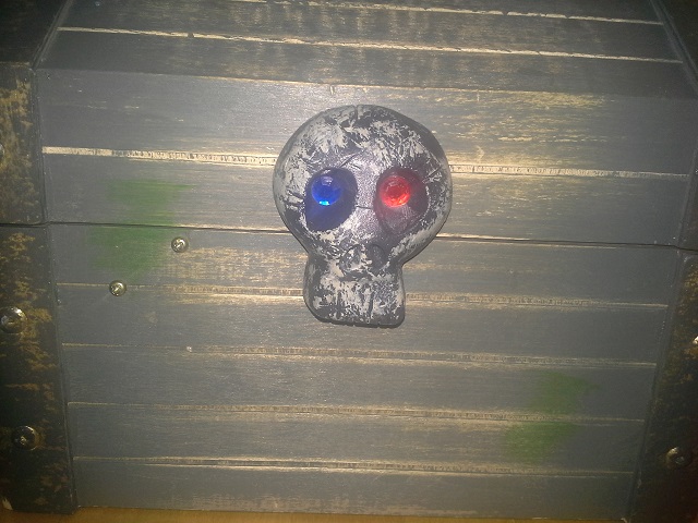
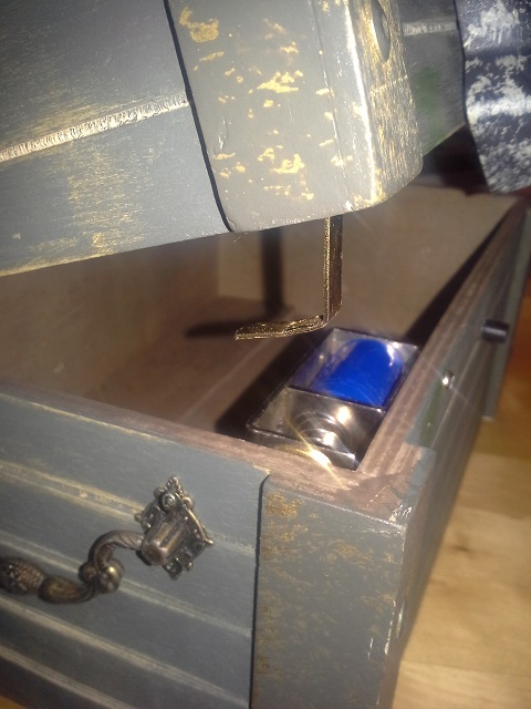
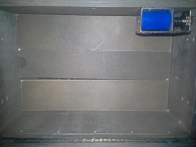
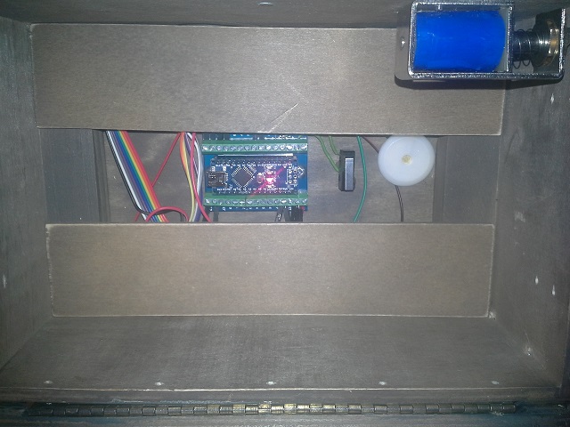
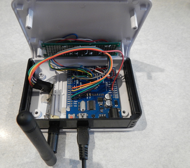
      My youngest son and I converted his toy pirate chest to include the secret knock sensor. Pictures are below. The chest we used is perfect as it already contained a false bottom which now hides the electronics. It would be relatively easy to add a false bottom into other chests. The only thing we still want to do is change the blue and red "crystal" eyes in the skull to LEDs that would flash with the secret knock sensor. The sample sketch was modified to only unlock for 5 seconds, otherwise the solenoid gets pretty hot, and also modified to not unlock at power up.

      Components Used:

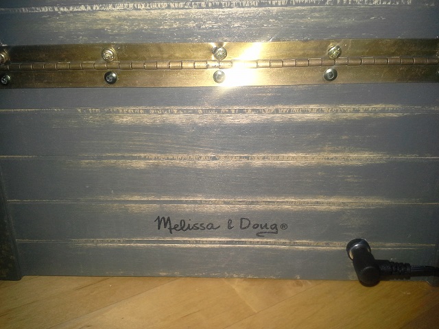
      • Melissa & Doug Pirate Chest
      • Arduino Nano
      • Nano Breakout Board
      • Sound Detection Sensor Module
      • 12V Solenoid
      • Voltage Regulator
      • Relay Module
      • NRF24L01+ Radio Module
      • Piezo Buzzer from the parts bin
      • Momentary Switch from the parts pin
      • 470uF 35V Electrolytic Capacitor from the parts bin
      • Power Supply Barrel Jack connector
      • 12V Wall Wart from the parts bin

      Build Notes:

      • We used the Nano with the breakout board so that it would be easier to mount to the wood bottom. Any other Arduino should work as well.
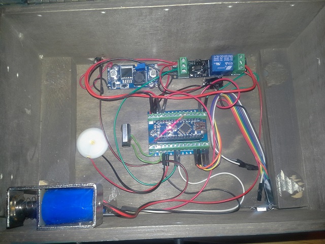
      • We used the voltage regulator module to protect the Nano (as much as possible) in case the kids plugged the wrong wall wart into it.
      • We had to add the 470uF capacitor as about 50% of the time when the solenoid activated, the power fluctuations would cause the Nano to reset. With the capacitor added, there has been no issue with resets.
      • You need a fairly beefy wall wart. Although the specs indicate the solenoid is .35A, it seems to draw more than that. I haven't measured the actual usage yet.
      • We were planning to use a TIP120 Darlington Transistor to switch the solenoid on and off, but I was worried that it would get fairly hot so went with a relay instead.
      • Given the current draw of the solenoid we went with a wall-wart rather than with batteries.
      • Some parts (Nano and Voltage Regulator) were screwed down to the bottom, but most have a small dollop of hot glue to hold them down.
      • Total build cost, not including the pirate chest (which was a gift), was about US $20.

      Cheers
      Al

      1.jpg
      2.jpg
      3.jpg
      4.jpg
      5.jpg
      6.jpg

      posted in My Project
      Sparkman
      Sparkman
    • Sprinkler Controller

      Hi all,

      Inspired by @BulldogLowell's Irrigation Controller, I set out to build a controller to work in conjunction with my RainBird Controller. The primary reason for doing it this way is that the RainBird controller is very reliable, albeit not very smart. I wanted additional smarts, but did not want to forego the reliability of the RainBird, so I set out to build a controller that has the best of both worlds. The controller is still a work in progress, but the base functionality is now in place and I will hook it up this weekend. All of the smarts are in my HomeSeer 3 HA system (HS3), so right now the Mega just listens and processes commands from the HS3 MySensors Plugin. The HS3 MySensors plugin does not support the retrieval of variables used in BulldogLowell's controller, so I had to do things slightly different. I'll post my sketch in a few days.

      As you can see from the picture below, there are 3 sets of relays:

      8x 5VDC Relays controlled by the Arduino
      8x 24VAC Relays controlled by the 5VDC Relays and the outputs of the RainBird Controller (wiring to the RainBird not shown)
      2x 5VDC Relay which is used to activate the rain sensor input on the RainBird controller and is used for the controlling the main valve (needs to be installed). Activating the rain sensor input effectively bypasses the RainBird controller.

      The 24VAC relays are DPDT and I'm using one pole of each relay as an input to the Arduino. That way I can detect if the RainBird is controlling a zone and also whether the command to activate a relay by the Arduino was successful. The second pole of each 24VAC relay is used to control the actual zone valve. The outputs of the 24VAC relays are connected through a surge protector that I had bought a few years ago to use with a different controller (the ground wire is not connected yet and the wires from the surge protector to the valves are not shown).

      sprinkler controller.jpg

      Here are the components used in the controller:

      • Arduino Mega
      • Arduino Mega Prototype Shield
      • NRF24L01+ with PA/LNA mounted to a spare relay socket
      • SMA Female Bulkhead
      • SMA Extension Cable
      • 2 Channel Relay Module
      • 8 Channel Relay Module
      • 16x2 LCD Module
      • Idec SY2S-05C Relay Sockets
      • Idec RY2S-U-AC24V Relays
      • Aluminum Slotted DIN Rail
      • TManufacturing Sprinkler Surge Protector
      • DSC Alarm Panel Enclosure (door not shown)
      • Terminal Strips
      • 24VAC to 5VDC Power Supply
      • Cables: CAT5e to interconnect relays to the Mega, 7 wire sprinkler cable, Dupont cables, etc.

      Still to do:

      • Connect and update the sketch for my DLJ Water Meter that will be installed on the water line for the sprinkler system. This way I can detect if a sprinkler valve is stuck open (i.e. if all of the valves should be closed, but there is still flow, then there's a problem).
      • Update the sketch with a watchdog timer. The Arduino will try and connect to my HS3 system on a regular basis and if it fails for a period of time, the relay for the RainBird bypass will open, allowing the RainBird controller to take over.
      • Add a 24VAC to 5VDC power supply so that I don't need to use two separate power supplies. The 24VAC supply is shared between this controller and the RainBird.

      Cheers
      Al

      posted in My Project
      Sparkman
      Sparkman
    • RE: Project boxes for MySensor's nodes and gateway?

      @NeverDie I use an assortment of cases and still looking for others for some sensors I have built. To be honest, I think that finding the right case is the hardest part of the MySensors system 😄

      For my gateway, I used this box: http://imall.itead.cc/project-case-white-and-black-110-80-25mm.html. It's a tight squeeze with the Uno and NRF24L01+ PA/LNA along with a small proto board to mount the LEDs. A smaller Arduino would fit better, but I used an Uno clone to ensure enough power for the PA/LNA module. I had to remove the Uno headers in order for it to fit as the headers were interfering with the circuit board for the LEDs. I'll open it up and take some pics.

      I've been looking at these cases for indoor battery powered sensors. They are a good price, but are only in inventory in the UK, so shipping is $25 for any quantity, so I'll have to do a large enough order to minimize the shipping cost per unit.

      Cheers
      Al

      MySensors Gateway Outside.png
      MySensors Gateway Inside.png
      MySensors Gateway LEDs.png

      posted in Enclosures / 3D Printing
      Sparkman
      Sparkman
    • RE: Can't program Arduino Nano Compatible modules

      A lot of the clones use a ch340g usb interface chip. Have you downloaded drivers for it: http://sparks.gogo.co.nz/ch340.html.

      Cheers
      Al

      posted in Troubleshooting
      Sparkman
      Sparkman
    • RE: Water Flow sensor

      @mrc-core I believe this type of meter outputs 4.5 pulses per liter, but there are a number of different specs for similar meters. Do you have a link to the one that you actually purchased? The example sketch is for meters that output 1 pulse per liter (or 1000 pulses for 1 cubic meter). Therefore change PULSE_FACTOR to 4500 in the sketch. You may need to adjust that number. I would get a large bucket for which you know how many liters it is and then count the number of pulses required to fill it. Take that number, divide it by the size of the bucket (in liters) and then multiply by 1000. That number becomes your PULSE_FACTOR.

      Cheers
      Al

      posted in My Project
      Sparkman
      Sparkman
    • RE: Any mass produced prototyping shields for the pro mini?

      @NeverDie Not exactly mass produced, but here are some other options:

      https://oshpark.com/shared_projects/uXIff7XO

      https://oshpark.com/shared_projects/pRJiKWxV

      https://oshpark.com/shared_projects/nJ8HNuZj

      Cheers
      Al

      posted in My Project
      Sparkman
      Sparkman
    • RE: Robot mower ignores the rain, MySensors to the rescue!

      Hi Mark,

      The only example I can think of is @BulldogLowell's sprinkler controller. It queries for run-times from the controller. I think that is supported on the Vera, and not sure if Domoticz supports the same feature.

      Cheers
      Al

      posted in Domoticz
      Sparkman
      Sparkman
    • RE: Where do you find IR code ?

      @Sebastien-Vayrette-Gavard Sorry, I thought there was a converter online that would convert from pronto to the code needed by this sketch. The one I thought would work is coming up with an error when I run it. I haven't looked into the details of the IR library included with MySensors. There's likely a way to manually convert between the two (there are good descriptions on what the pronto codes mean here: http://www.hifi-remote.com/infrared/IR-PWM.shtml and here: http://www.remotecentral.com/features/irdisp2.htm). You could likely use a different IR library/sketch as well that's meant for sending pronto codes. Here's are a few: https://github.com/probonopd/arduino-infrared-pronto and http://irdb.tk/send/. The other option you have is to build an IR receiver and then use the remote you have to learn the code.

      Cheers
      Al

      posted in Troubleshooting
      Sparkman
      Sparkman
    • RE: Piezo Buzzer

      @n3ro That should work fine. You may want to add a resistor to limit current. Once you have one, I would measure actual current draw and see if a resistor is needed. Based on the specs provided, you should not need one, but you never know how accurate the specs are.

      Cheers
      Al

      posted in Hardware
      Sparkman
      Sparkman
    • RE: Pirate Chest with Secret Knock Sensor

      I've updated the original post with a parts list and some build notes.

      Cheers
      Al

      posted in My Project
      Sparkman
      Sparkman
    • RE: Can't ping Ethernet Gateway

      @mscott Have you tried the 5200 without the NRF24 hooked up and some test libraries for it to ensure it is working? I believe you can just use "Ethernet.begin(mac);" and it will try to get an ip address using DHCP. I have a couple of Ethernet modules for my Arduinos, but I haven't used them much, so I'm definitely no expert on them.

      Cheers
      Al

      posted in Troubleshooting
      Sparkman
      Sparkman
    • RE: Best platform (currently) for running RFM69HW?

      For me it's primarily a cost driven decision. I can get a Pro Mini and an NRF24L01+ for a total price, including shipping to Canada, for less than $3US in total. The cheapest RFM69 module is $3.90 + $6.55 shipping and then the cost of a Pro Mini. A Moteino equipped with a RFM69 is almost $20, not including shipping. At some point I may experiment with different RF modules, but so far the NRF clones/fakes have been working fine for me with coverage throughout the 3 levels in my house and in our yard.

      Cheers
      Al

      posted in Hardware
      Sparkman
      Sparkman
    • RE: Irrigation Controller (up to 16 valves with Shift Registers)

      @BulldogLowell Thanks for posting this. A sprinkler controller to replace my Rainbird controller is next on my list of projects.

      For those looking for a good and relatively cheap soil moisture sensor, these ones are pretty good and use a capacitive sensor: http://www.ebay.com/itm/261675851824. They transmit on 433 MHz. I currently use them with RFXCom and HomeSeer, but for those that don't have RFXCom, the protocol should be relatively easy to reverse engineer and then use directly with MySensors and a 433MHz receiver. I've also bought a few from here: https://www.plantcaretools.com/en/webshop/wireless-moisture-sensor-en-detail. Both sellers were good to deal with. The only drawback to them is that the antenna (and therefore range) is not very good, but there is an easy mod to improve that: http://www.domoticz.com/forum/viewtopic.php?f=13&t=2712

      Cheers
      Al

      posted in My Project
      Sparkman
      Sparkman
    • RE: Gateway on Raspberry Pi not responding properly [SOLVED]

      @mfalkvidd Looks like it was working much better with the old gateway as it found the parent and a node ID got assigned. There are still some communication issues though will all of the fails at the end. If the sensor is sending a bunch of info right after each other, it may be cause by power brownouts. Try putting a small delay between each send to see if that improves it. On your Rpi2, there must be some type of communication issue between the hardware and Domoticz. I believe the gateway is completely stateless. There may not be an easy way to make the gateway more verbose. You could add some println statements in the code manually.

      Cheers
      Al

      posted in Troubleshooting
      Sparkman
      Sparkman
    • RE: Best platform (currently) for running RFM69HW?

      @NeverDie Here's the link to the OSH Park Teensy adapter board: https://oshpark.com/shared_projects/RIumMBtN

      These guys have an an adapter board as well, but a bit pricey: http://modtronicsaustralia.com/shop/rfm69hw-breakout-board-bare-pcb-rf-wireless-module/

      Cheers
      Al

      posted in Hardware
      Sparkman
      Sparkman
    • RE: Irrigation Controller (up to 16 valves with Shift Registers)

      @epierre said:

      Do you think I I could use that kind of design in parallel of a static watering controller, so I could have the basic program with the controller, and manage extras with the arduino/mysensors ?

      Inspired by @BulldogLowell's controller, I've been working on a MySensors irrigation controller that works in parallel with my RainBird Controller. I'm using a double set of relays (one 5VDC set that's controlled by the Arduino and a 24VAC set that's controlled by the 5VDC relays and the RainBird). This way I can also sense in my HA system when the valves have been opened by the RainBird controller. I have the base functionality finished and working on some additional bells and whistles. Will post some details in a separate thread later today.

      Cheers
      Al

      posted in My Project
      Sparkman
      Sparkman
    • RE: How to wire for battery level measure?

      @msebbe said:

      Also, could I wire so both resistors meet at A0?

      Yes, that is fine.

      Cheers
      Al

      posted in Troubleshooting
      Sparkman
      Sparkman
    • RE: Best platform (currently) for running RFM69HW?

      Here's another option: https://github.com/uChip/RFM69W_BOB

      posted in Hardware
      Sparkman
      Sparkman
    • RE: LG TV controller

      @sundberg84 I'm not sure if any of the current LG TV's have an RS232 port anymore. Most new ones (at least the "smart" ones) are now running WebOS and can in theory be controlled through it over IP. I have two LG TV's, one is a 2010 and it has a serial port, but my 2012 Smart TV does not.

      Cheers
      Al

      posted in My Project
      Sparkman
      Sparkman
    • RE: Dimmer and automaticly turn "on" and "off" the light

      @jacek In your icomingMessage routine, it looks you have no code to turn the light off, although I might be misinterpreting it.

      Cheers
      Al

      posted in Troubleshooting
      Sparkman
      Sparkman
    • RE: Adapter for RFM69 on NRF24L01+ pinout-header

      @GertSanders There are these: https://oshpark.com/shared_projects/TKNcHTRl

      Cheers
      Al

      posted in Hardware
      Sparkman
      Sparkman
    • RE: Video How To - Phoney TV

      @jimbolaya Something like this should work: http://www.digikey.com/products/en?keywords=IPP055N03LGXKSA1-ND.

      posted in My Project
      Sparkman
      Sparkman
    • RE: Dimmer and automaticly turn "on" and "off" the light

      @jacek It looks like you have an endless loop to me,
      To initiate turning off the light due to a high ambient level, you call gw.send(dimmerMsg.set(0), true); which will instruct domoticz to send a command back which should be acted upon in your incomingMessage routine. In that routine, if the ambient light level is high, you send the same command back to domoticz: gw.send(dimmerMsg.set(0), true);. It's not clear to me what the rest of the functions after that do but they won't be executed due to your return command. What does the serial output show when high ambient light triggers this?

      posted in Troubleshooting
      Sparkman
      Sparkman
    • RE: Safe In-Wall AC to DC Transformers??

      Transformers typically have an in-rush current as well, so a fast-blow fuse could pop because of this if it's not sized for that.

      Cheers
      Al

      posted in Hardware
      Sparkman
      Sparkman
    • RE: Video How To - Phoney TV

      @jimbolaya Sorry, link is now fixed.

      posted in My Project
      Sparkman
      Sparkman
    • RE: Dimmer and automaticly turn "on" and "off" the light

      @jacek As I mentioned, you call gw.send(dimmerMsg.set(0), true); again in the incomingMessage routine. By doing that, you are asking Domoticz to send another off command. Instead you should have a command there to actually set the dim level on the pins to the value that you want. I'm not too familiar with this code, but looking at it, you should just save the new state there and then continue with the routine, rather than calling return;

      Cheers
      Al

      posted in Troubleshooting
      Sparkman
      Sparkman
    • RE: Sensebender Micro

      I received mine today. I would be interested in a lower cost version as well that doesn't include the temp & humidity sensor.

      Cheers
      Al

      posted in Announcements
      Sparkman
      Sparkman
    • RE: Sketch for Lightning Sensor

      My radios showed up a few days ago and this is the sketch I'm using:

      #include "MySensor.h"  
      
      // the sensor communicates via SPI or I2C. This example uses the SPI interface
      #include "SPI.h"
      // include Playing With Fusion AXS3935 libraries
      #include "PWFusion_AS3935.h"
      
      // setup CS pins used for the connection with the sensor
      // other connections are controlled by the SPI library)
      int8_t CS_PIN  = 8;
      int8_t SI_PIN  = 7;
      int8_t IRQ_PIN = 3;                      
      volatile int8_t AS3935_ISR_Trig = 0;
      
      // #defines
      #define AS3935_INDOORS       1
      #define AS3935_OUTDOORS      0
      #define AS3935_DIST_DIS      0
      #define AS3935_DIST_EN       1
      #define AS3935_CAPACITANCE   96      // <-- SET THIS VALUE TO THE NUMBER LISTED ON YOUR BOARD 
      // prototypes
      void AS3935_ISR();
      
      PWF_AS3935  lightning0(CS_PIN, IRQ_PIN, SI_PIN);
      
      #define CHILD_ID_DISTANCE 1
      #define CHILD_ID_INTENSITY 2
      MySensor gw;
      MyMessage msgDist(CHILD_ID_DISTANCE, V_DISTANCE);
      MyMessage msgInt(CHILD_ID_INTENSITY, V_VAR1);
      
      void setup()  
      { 
        gw.begin();
      
        // Send the sketch version information to the gateway and Controller
        gw.sendSketchInfo("Lightning Sensor", "1.0");
      
        // Register all sensors to gw (they will be created as child devices)
        gw.present(CHILD_ID_DISTANCE, S_DISTANCE);
        gw.present(CHILD_ID_INTENSITY, S_CUSTOM);
        boolean metric = gw.getConfig().isMetric;
      
        Serial.begin(115200);
        Serial.println("Playing With Fusion: AS3935 Lightning Sensor, SEN-39001");
        Serial.println("beginning boot procedure....");
        
        // setup for the the SPI library:
        SPI.begin();                            // begin SPI
        SPI.setClockDivider(SPI_CLOCK_DIV4);    // SPI speed to SPI_CLOCK_DIV16/1MHz (max 2MHz, NEVER 500kHz!)
        SPI.setDataMode(SPI_MODE1);             // MAX31855 is a Mode 1 device
                                                //    --> clock starts low, read on rising edge
        SPI.setBitOrder(MSBFIRST);              // data sent to chip MSb first 
        
        lightning0.AS3935_DefInit();                        // set registers to default  
        // now update sensor cal for your application and power up chip
        lightning0.AS3935_ManualCal(AS3935_CAPACITANCE, AS3935_OUTDOORS, AS3935_DIST_EN);
                        // AS3935_ManualCal Parameters:
                        //   --> capacitance, in pF (marked on package)
                        //   --> indoors/outdoors (AS3935_INDOORS:0 / AS3935_OUTDOORS:1)
                        //   --> disturbers (AS3935_DIST_EN:1 / AS3935_DIST_DIS:2)
                        // function also powers up the chip
                        
        // enable interrupt (hook IRQ pin to Arduino Uno/Mega interrupt input: 0 -> pin 2, 1 -> pin 3 )
        attachInterrupt(1, AS3935_ISR, RISING);
      
        lightning0.AS3935_PrintAllRegs();
        
        // delay execution to allow chip to stabilize.
        delay(1000);
      
      }
      
      void loop()      
      {     
      
        // This program only handles an AS3935 lightning sensor. It does nothing until 
        // an interrupt is detected on the IRQ pin.
        while(0 == AS3935_ISR_Trig){}
       
        // reset interrupt flag
        AS3935_ISR_Trig = 0;
        
        // now get interrupt source
        uint8_t int_src = lightning0.AS3935_GetInterruptSrc();
        if(0 == int_src)
        {
          Serial.println("Unknown interrupt source");
          //gw.send(msgDist.set(999));
          //gw.send(msgInt.set(0));
        }
        else if(1 == int_src)
        {
          uint8_t lightning_dist_km = lightning0.AS3935_GetLightningDistKm();
          uint32_t lightning_intensity = lightning0.AS3935_GetStrikeEnergyRaw();
      
          Serial.print("Lightning detected! Distance to strike: ");
          Serial.print(lightning_dist_km);
          Serial.println(" kilometers");
          Serial.print("Lightning detected! Lightning Intensity: ");
          Serial.println(lightning_intensity);
          gw.send(msgDist.set(lightning_dist_km));
          gw.send(msgInt.set(lightning_intensity));
        }
        else if(2 == int_src)
        {
          Serial.println("Disturber detected");
          //gw.send(msgDist.set(998));
          //gw.send(msgInt.set(0));
        }
        else if(3 == int_src)
        {
          Serial.println("Noise level too high");
          //gw.send(msgDist.set(997));
          //gw.send(msgInt.set(0));
        }
      }
      
      // this is irq handler for AS3935 interrupts, has to return void and take no arguments
      // always make code in interrupt handlers fast and short
      void AS3935_ISR()
      {
        AS3935_ISR_Trig = 1;
      }
      

      It seems to be working (based on what I'm seeing using the serial monitor) and updating my controller (HomeSeer), although hard to know how well it's working without lightning in the area. I'll have to find a way to simulate lightning.

      I have both the lightning sensor and the radio hooked up to the SPI bus.

      Nano with NRF24L01 and AS3935_bb.png

      Cheers
      Al

      EDIT: The diagram above is incorrect, I had to connect the lightning sensor breakout board to 5V, it did not seem to work at 3.3V in this configuration.

      posted in Development
      Sparkman
      Sparkman
    • RE: How would I interface with Protection 1 alarm sensors?

      @JoeStrout You're welcome. It's not too difficult replacing a panel. When I bought my house it had an old DSC panel, but it was locked out (this is typically done with security panels installed by security monitoring companies) and I replaced it with a new board and new keypads and programmed it from scratch. I would go with the PC1632 or even 64. They only cost a few dollars more for quite a bit of expandability. There are a number of forums around where you can get help programming it. The ones I used in the past were this one: http://security.livewatch.com/forum and this one: http://cocoontech.com/forums/forum/14-home-security/.

      Cheers
      Al

      posted in General Discussion
      Sparkman
      Sparkman
    • RE: Sensebender Micro

      @ServiceXp Good point. Maybe for the low values it's transmitting the temp/humidity when it's calculating the battery level. I'll take a look at the sketch to see if that could be the case.

      Cheers
      Al

      posted in Announcements
      Sparkman
      Sparkman
    • RE: Sketch for Lightning Sensor

      @jeylites Thanks, I appreciate the offer. July/August are prime thunderstorm season where I live and they are forecasting a possible thunderstorm for today, so I'm hoping to confirm that everything is working today 🙂

      Cheers
      Al

      posted in Development
      Sparkman
      Sparkman
    • RE: mega 2560

      @Andy-Pep Hi Andy, yes it's supported. I'm using one as a sprinkler controller. It has more memory and more inputs/outputs, so any time that's a factor, it's a good board to use.

      Cheers
      Al

      posted in General Discussion
      Sparkman
      Sparkman
    • RE: Sensebender Micro

      @ServiceXp Your hunch was correct. I built another Sensebender that only transmitted battery levels, and it's battery levels did not vary at all:

      sb1.PNG

      I then modified the sketch to put a short wait after the temp & humidity are sent to allow the voltage level to recover and the battery levels do not fluctuate so far. However, I'm thinking it would be better to always measure right after a transmit, but not sure if that's easy to do.

      Cheers
      Al

      posted in Announcements
      Sparkman
      Sparkman
    • RE: Wireless nRF24L01+ sniffer for MySensors

      In case anyone else is interested, I updated the sketch to work with a 20x4 LCD screen so that you can see how many packets have been captured. I used this LCD screen connected to the I2C interface. Make sure you get the correct LCD libraries for it as the default LCD libraries don't work with it. There's a link for them on the eBay page.

      EDIT: There seems to be an issue capturing packets if it's also connected to the nrf24sniff program. It works fine standalone and also when BINARY_OUTPUT is undefined and talking to the Serial Monitor. I'l need to do more troubleshooting as to why.

      DSCN3131.png

      Cheers
      Al

      /*
        NRF24_Sniff - An Arduino sketch to promiscuous capture all wireless
                      traffic generated by Nordic Semi. NRF24L01+ modules.
      
        Created by Ivo Pullens, Emmission, 2014 -- www.emmission.nl
        Updated by Sparkman, 2015 - added LCD support
      
        This program is free software: you can redistribute it and/or modify
        it under the terms of the GNU General Public License as published by
        the Free Software Foundation, either version 3 of the License, or
        (at your option) any later version.
      
        This program is distributed in the hope that it will be useful,
        but WITHOUT ANY WARRANTY; without even the implied warranty of
        MERCHANTABILITY or FITNESS FOR A PARTICULAR PURPOSE.  See the
        GNU General Public License for more details.
      
        You should have received a copy of the GNU General Public License
        along with this program.  If not, see <http://www.gnu.org/licenses/>.
      */   
       
      #include <Arduino.h>
      #include <SPI.h>
      #include <CircularBuffer.h>
      #include <RF24.h>
      #include <RF24_config.h>
      
      #include <Wire.h>
      #include <LiquidCrystal_I2C.h>
      
      #define LED_SUPPORTED
      #define LCD_SUPPORTED
      
      // Hardware configuration
      #define RF_CE_PIN                      (9)
      #define RF_CS_PIN                      (10)
      #define RF_IRQ_PIN                     (2)
      #define RF_IRQ                         (RF_IRQ_PIN-2)                                           // Usually the interrupt = pin -2 (on uno/nano anyway)
      
      #ifdef LED_SUPPORTED
      	#define LED_PIN_LISTEN         (A0)
      	#define LED_PIN_RX             (A1)
      	#define LED_PIN_TX             (A2)
      	#define LED_PIN_CONFIG         (A3)
      	#define LED_PIN_BUFF_FULL      (A4)
      #endif
      
      #ifdef LCD_SUPPORTED
      	LiquidCrystal_I2C lcd(0x27,20,4);  // set the LCD address to 0x27 for a 20 chars and 4 line display
      #endif
      
      static uint32_t PacketCount = 0;
      static uint8_t lostPacketCount = 0;
      
      #define RF_MAX_ADDR_WIDTH              (5)                                                      // Maximum address width, in bytes. MySensors use 5 bytes for addressing, where lowest byte is for node addressing.
      #define MAX_RF_PAYLOAD_SIZE            (32)
      #define SER_BAUDRATE                   (115200)
      #define PACKET_BUFFER_SIZE             (30)                                                     // Maximum number of packets that can be buffered between reception by NRF and transmission over serial port.
      #define PIPE                           (0)                                                      // Pipe number to use for listening
      
      // Startup defaults until user reconfigures it
      #define DEFAULT_RF_CHANNEL             (76)                                                     // 76 = Default channel for MySensors.
      #define DEFAULT_RF_DATARATE            (RF24_250KBPS)                                           // Datarate
      #define DEFAULT_RF_ADDR_WIDTH          (RF_MAX_ADDR_WIDTH)                                      // We use all but the lowest address byte for promiscuous listening. First byte of data received will then be the node address.
      #define DEFAULT_RF_ADDR_PROMISC_WIDTH  (DEFAULT_RF_ADDR_WIDTH-1)
      #define DEFAULT_RADIO_ID               ((uint64_t)0xA8A8E1FC00LL)                               // 0xA8A8E1FC00LL = MySensors v2 (1.4) default
      #define DEFAULT_RF_CRC_LENGTH          (2)                                                      // Length (in bytes) of NRF24 CRC
      #define DEFAULT_RF_PAYLOAD_SIZE        (MAX_RF_PAYLOAD_SIZE)                                    // Define NRF24 payload size to maximum, so we'll slurp as many bytes as possible from the packet.
      
      // If BINARY_OUTPUT is defined, this sketch will output in hex format to the PC.
      // If undefined it will output text output for development.
      #define BINARY_OUTPUT
      
      #include "NRF24_sniff_types.h"
      
      #ifndef BINARY_OUTPUT
      	int my_putc( char c, FILE *t )
      	{
      	  Serial.write( c );
      	}
      #endif
      
      // Set up nRF24L01 radio on SPI bus plus CE/CS pins
      static RF24 radio(RF_CE_PIN, RF_CS_PIN);
      
      static NRF24_packet_t bufferData[PACKET_BUFFER_SIZE]; 
      static CircularBuffer<NRF24_packet_t> packetBuffer(bufferData, sizeof(bufferData)/sizeof(bufferData[0]));
      static Serial_header_t serialHdr;
      static volatile Serial_config_t conf = {
      	DEFAULT_RF_CHANNEL,     DEFAULT_RF_DATARATE, DEFAULT_RF_ADDR_WIDTH,
      	DEFAULT_RF_ADDR_PROMISC_WIDTH,  DEFAULT_RADIO_ID,    DEFAULT_RF_CRC_LENGTH,
      	DEFAULT_RF_PAYLOAD_SIZE
      	};
      
      #define GET_PAYLOAD_LEN(p) ((p->packet[conf.addressLen-conf.addressPromiscLen] & 0xFC) >> 2) // First 6 bits of nRF header contain length.
      
      
      inline static void dumpData(uint8_t* p, int len)
      {
      	#ifndef BINARY_OUTPUT
      		while (len--) { printf("%02x", *p++); }
      		Serial.print(' ');
      	#else
      		Serial.write(p, len);
      	#endif
      }
      
      static void handleNrfIrq()
      {
      	// Loop until RX buffer(s) contain no more packets.
      	while (radio.available())
      	{
      		#ifdef LED_SUPPORTED
      			digitalWrite(LED_PIN_RX, HIGH);
      		#endif
      		if (!packetBuffer.full())
      		{
      			#ifdef LED_SUPPORTED
      				digitalWrite(LED_PIN_BUFF_FULL, LOW);
      			#endif
      
      			NRF24_packet_t* p = packetBuffer.getFront();
      			p->timestamp = micros();  // Micros does not increase in interrupt, but it can be used.
      			p->packetsLost = lostPacketCount;
      			uint8_t packetLen = radio.getPayloadSize();
      			if (packetLen > MAX_RF_PAYLOAD_SIZE)
      				packetLen = MAX_RF_PAYLOAD_SIZE;
      		  
      			radio.read( p->packet, packetLen );
      		      
      			// Determine length of actual payload (in bytes) received from NRF24 packet control field (bits 7..2 of byte with offset 1)
      			// Enhanced shockburst format is assumed!
      			if (GET_PAYLOAD_LEN(p) <= MAX_RF_PAYLOAD_SIZE)
      			{
      				// Seems like a valid packet. Enqueue it.
      				packetBuffer.pushFront(p);
      				PacketCount++;
      			}    
      			else
      			{
      			// Packet with invalid size received. Could increase some counter...
      			}
      			lostPacketCount = 0;
      		}
      		else
      		{
      			// Buffer full. Increase lost packet counter.
      			#ifdef LED_SUPPORTED
      				digitalWrite(LED_PIN_BUFF_FULL, HIGH);
      			#endif
      
      			bool tx_ok, tx_fail, rx_ready;
      			if (lostPacketCount < 255)
      				lostPacketCount++;
      			// Call 'whatHappened' to reset interrupt status.
      			radio.whatHappened(tx_ok, tx_fail, rx_ready);
      			// Flush buffer to drop the packet.
      			radio.flush_rx();
      		}
      		#ifdef LED_SUPPORTED
      		    digitalWrite(LED_PIN_RX, LOW);
      		#endif
      	}
      }  
      
      static void activateConf( void )
      {
      	#ifdef LED_SUPPORTED
      		digitalWrite(LED_PIN_CONFIG, HIGH);
      	#endif
      
      	// Match MySensors' channel & datarate
      	radio.setChannel(conf.channel);
      	radio.setDataRate((rf24_datarate_e)conf.rate);
      
      	// Disable CRC & set fixed payload size to allow all packets captured to be returned by Nrf24.
      	radio.disableCRC();
      	radio.setPayloadSize(conf.maxPayloadSize);
      
      	// Configure listening pipe with the 'promiscuous' address and start listening
      	radio.setAddressWidth(conf.addressPromiscLen);
      	radio.openReadingPipe( PIPE, conf.address >> (8*(conf.addressLen - conf.addressPromiscLen)) );
      	radio.startListening();
      
      	// Attach interrupt handler to NRF IRQ output. Overwrites any earlier handler.
      	attachInterrupt(RF_IRQ, handleNrfIrq, FALLING);    // NRF24 Irq pin is active low.
      
      	// Initialize serial header's address member to promiscuous address.
      	uint64_t addr = conf.address;  // TODO: probably add some shifting!
      	for (int8_t i = sizeof(serialHdr.address)-1; i >= 0; --i)
      	{
      		serialHdr.address[i] = addr;
      		addr >>= 8;
      	}
      
      	// Send config back. Write record length & message type
      	uint8_t lenAndType = SET_MSG_TYPE(sizeof(conf), MSG_TYPE_CONFIG);
      	dumpData(&lenAndType, sizeof(lenAndType));
      	// Write config
      	dumpData((uint8_t*)&conf, sizeof(conf) );
      
      	#ifndef BINARY_OUTPUT
      		Serial.print("Channel:     "); Serial.println(conf.channel);
      		Serial.print("Datarate:    ");
      		switch (conf.rate)
      		{
      			case 0: Serial.println("1Mb/s"); break;
      			case 1: Serial.println("2Mb/s"); break;
      			case 2: Serial.println("250Kb/s"); break;
      		}
      		Serial.print("Address:     0x");
      		uint64_t adr = conf.address;
      		for (int8_t i = conf.addressLen-1; i >= 0; --i)
      		{
      			if ( i >= conf.addressLen - conf.addressPromiscLen )
      			{
      				Serial.print((uint8_t)(adr >> (8*i)), HEX);
      			}
      			else
      			{
      				Serial.print("**");
      			}
      		}
      		Serial.println("");
      		Serial.print("Max payload: "); Serial.println(conf.maxPayloadSize);
      		Serial.print("CRC length:  "); Serial.println(conf.crcLength);
      		Serial.println("");
      		 
      		radio.printDetails();
      
      		Serial.println("");
      		Serial.println("Listening...");
      	#endif
      	#ifdef LED_SUPPORTED
      		digitalWrite(LED_PIN_CONFIG, LOW);
      	#endif
      	#ifdef LCD_SUPPORTED
      		lcd.setCursor(0, 0);
      		lcd.print("CH ");
      		lcd.print(conf.channel);
      
      		switch (conf.rate)
      		{
      			case 0: lcd.print(" @ 1Mb/s"); break;
      			case 1: lcd.print(" @ 2Mb/s"); break;
      			case 2: lcd.print(" @ 250kb/s"); break;
      		}
      	#endif
      
      }
      
      void setup(void)
      {
      	#ifdef LED_SUPPORTED
      		pinMode(LED_PIN_LISTEN,    OUTPUT);
      		pinMode(LED_PIN_RX,        OUTPUT);
      		pinMode(LED_PIN_TX,        OUTPUT);
      		pinMode(LED_PIN_CONFIG,    OUTPUT);
      		pinMode(LED_PIN_BUFF_FULL, OUTPUT);
      		digitalWrite(LED_PIN_LISTEN,    LOW);
      		digitalWrite(LED_PIN_RX,        LOW);
      		digitalWrite(LED_PIN_TX,        LOW);
      		digitalWrite(LED_PIN_CONFIG,    LOW);
      		digitalWrite(LED_PIN_BUFF_FULL, LOW);
      	#endif
      
      	#ifdef LCD_SUPPORTED
      		lcd.init();                      // initialize the lcd 
      		lcd.backlight();
      		lcd.clear();
      		lcd.home();
      	#endif
      
      	Serial.begin(SER_BAUDRATE);
      
      	#ifndef BINARY_OUTPUT
      		fdevopen( &my_putc, 0);
      		Serial.println("-- RF24 Sniff --");
      	#endif
      
      	radio.begin();
      
      	// Disable shockburst
      	radio.setAutoAck(false);
      	radio.setRetries(0,0);
      
      	// Configure nRF IRQ input
      	pinMode(RF_IRQ_PIN, INPUT);
      
      	#ifdef LED_SUPPORTED
      		digitalWrite(LED_PIN_LISTEN, HIGH);
      	#endif
      	#ifdef LCD_SUPPORTED
      		lcd.setCursor(0, 1);
      		lcd.print(PacketCount);
      		lcd.print(" Packets");
      		lcd.setCursor(0, 2);
      		lcd.print(lostPacketCount);
      		lcd.print(" Lost Packets");
      	#endif
      
      	activateConf();
      }
      
      void loop(void)
      {
      	while (!packetBuffer.empty())
      	{
      		#ifdef LED_SUPPORTED
      			digitalWrite(LED_PIN_TX, HIGH);
      		#endif
      
      		// One or more records present
      		NRF24_packet_t* p = packetBuffer.getBack();
      		int serialHdrLen = sizeof(serialHdr) - (conf.addressLen - conf.addressPromiscLen);
      		serialHdr.timestamp   = p->timestamp;
      		serialHdr.packetsLost = p->packetsLost;
      	 
      		// Calculate data length in bits, then round up to get full number of bytes.
      		uint8_t dataLen = (    (serialHdrLen<<3)                 /* Serial packet header */
      			+ ((conf.addressLen - conf.addressPromiscLen)<<3) /* NRF24 LSB address byte(s) */
      			+ 9                                      /* NRF24 control field */
      			+ (GET_PAYLOAD_LEN(p) << 3)                /* NRF24 payload length */
      			+ (conf.crcLength << 3)                   /* NRF24 crc length */
      			+ 7                                      /* Round up to full nr. of bytes */
      			) >> 3;                                     /* Convert from bits to bytes */
      
      		// Write record length & message type
      		uint8_t lenAndType = SET_MSG_TYPE(dataLen, MSG_TYPE_PACKET);
      		dumpData(&dataLen, sizeof(lenAndType));
      		// Write serial header
      		dumpData((uint8_t*)&serialHdr, serialHdrLen );
      		// Write packet data
      		dumpData(p->packet, dataLen - serialHdrLen);
      
      		#ifndef BINARY_OUTPUT
      			if (p->packetsLost > 0)
      			{
      				Serial.print(" Lost: "); Serial.print(p->packetsLost);
      			}
      			Serial.println(""); 
      		#endif
      		// Remove record as we're done with it.
      		packetBuffer.popBack();
      		#ifdef LED_SUPPORTED
      			digitalWrite(LED_PIN_TX, LOW);
      		#endif
      	}
      
      	#ifdef LCD_SUPPORTED
      		lcd.setCursor(0, 1);
      		lcd.print(PacketCount);
      		lcd.print(" Packets");
      		lcd.setCursor(0, 2);
      		lcd.print(lostPacketCount);
      		lcd.print(" Lost Packets");
      	#endif
       
      	// Test if new config comes in
      	uint8_t lenAndType;
      	if (Serial.available() >= sizeof(lenAndType) + sizeof(conf))
      	{
      		lenAndType = Serial.read();
      		if ((GET_MSG_TYPE(lenAndType) == MSG_TYPE_CONFIG) && (GET_MSG_LEN(lenAndType) == sizeof(conf)))
      		{
      			// Disable nRF interrupt while reading & activating new configuration.
      			noInterrupts();
      			// Retrieve the new configuration
      			uint8_t* c = (uint8_t*)(&conf);
      			for (uint8_t i = 0; i < sizeof(conf); ++i)
      			{
      				*c++ = Serial.read();
      			}
      			// Clear any packets in the buffer and flush rx buffer.
      			packetBuffer.clear();
      			radio.flush_rx();
      			// Activate new config & re-enable nRF interrupt.
      			activateConf();
      			interrupts();
      		}
      		else
      		{
      			#ifndef BINARY_OUTPUT
      				Serial.println("Illegal configuration received!"); 
      			#endif
      			#ifdef LCD_SUPPORTED
      				lcd.setCursor(0, 3);
      				lcd.print("Illegal Config");
      			#endif
      		}
      	}
      }
      
      posted in Development
      Sparkman
      Sparkman
    • RE: Is it better to use RFM69HW/Nrf24L01 long-range on gateway?

      @Cliff-Karlsson In the long range variants, the LNA is for the receive side (does a better job amplifying the received signal) and the PA is to produce higher power output on the transmit side. I use a module with a LNA/PA for my gateway and also for nodes that are far away or behind a few walls.

      Cheers
      Al

      posted in General Discussion
      Sparkman
      Sparkman
    • RE: 2 or more DHT11 - Sensors on one Arduino NANO MYSENSOR

      @michlb1982

      A couple of things, you put the device to sleep so while it's asleep, it won't respond to the commands to change the relays. Since you are combining relays and sensors, you need to keep the unit awake and find a different way to send the sensor data occasionally. For the relay status, read the comments in the sketch. You are saving the relay state and then reading that on startup. You can eliminate all of that code and just set the relay to off in the setup section.

      Cheers
      Al

      posted in Development
      Sparkman
      Sparkman
    • RE: Possible to focus PIR "beam" ?

      @Cliff-Karlsson That should work, but I would try using tape first so that it is easy to readjust. Once you have it adjusted the way you want, then replace the tape with paint.

      posted in General Discussion
      Sparkman
      Sparkman
    • RE: Sketch for Lightning Sensor

      Hi all,

      Well I was finally home when a thunderstorm rolled through and I was able to test the sensor and the sketch. Even though the sensor appeared to be working at 3.3V, I had to change it to 5V to get it to work properly with the USB powered Nano I have it connected to. I modified the sketch slightly (updated in my earlier post) to no longer send data when disturbers or unknown interrupt sources were detected. It's working great now and just need to put it into a case. I may use a different Arduino as well.

      Cheers
      Al

      posted in Development
      Sparkman
      Sparkman
    • RE: Sketch for Lightning Sensor

      @hek said:

      Sweet. Would you want to create a pull request when you're ready with this example (including AS3935 library)?

      Hi Henrik,

      Pull request submitted. Hopefully I did it correctly.

      Cheers
      Al

      posted in Development
      Sparkman
      Sparkman
    • RE: Sensebender Micro...no GW?

      @Lucas-Figg Technically the Sensebender is just an Arduino with integrated temp/humidity sensors and could be used without the MySensors ecosystem. It has additional IO pins so more sensors could be hooked up to it and likely a different radio module as well.

      Cheers
      Al

      posted in Development
      Sparkman
      Sparkman