Navigation

    • Register
    • Login
    • OpenHardware.io
    • Categories
    • Recent
    • Tags
    • Popular
    1. Home
    2. TD22057
    3. Best
    • Profile
    • Following
    • Followers
    • Topics
    • Posts
    • Best
    • Groups

    Best posts made by TD22057

    • Mother/Daughter board system

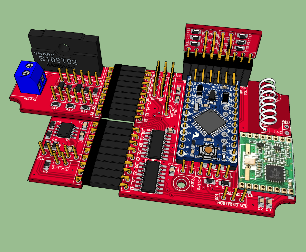
      I'd like to share my latest design. It's a mother/daughter board design using an RFM69 radio (though it would be easy to change it to an NRF). I have about 10 sensors I need to make and they're all similar, but not quite the same. This system allows be to mix and match what I need for each application. It's designed to be AC powered (which isn't a problem for my needs) and uses the following case for all of them (~$3/apiece for 10). I'm not trying to get the smallest form factor - I want something that's easy to build and looks nice. I needed a decent size case because I use a lot of detachable connectors and have at least one switch and 1-4 LED's on the front all of which intrude into the interior volume.

      The main board has the basic components and supports two daughter boards (roughly 25mm x 35mm) which plug into the side so the whole assembly is basically flat (leaving more room in the case for the switches, connectors, and LED's). An additional third daughter board can be used for small boards mounted perpendicular to the main boards (the sensor board below does that) or mounting over the top of the arduino.

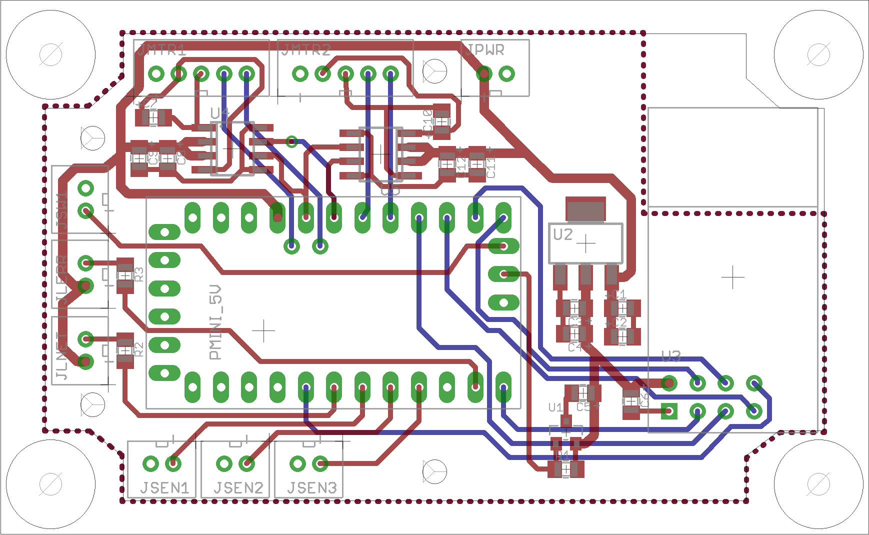
      The main board contains:

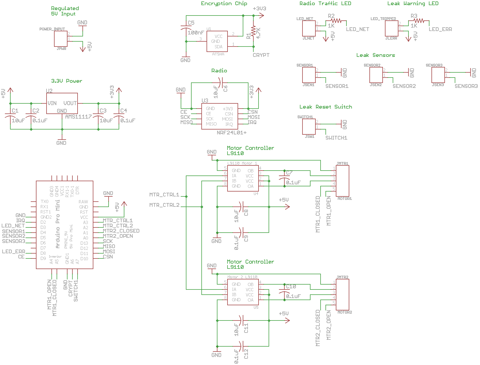
      • 3.3V Arduino Pro Mini
      • RFM69 radio
        • side mount for external dipole antenna
        • interior mount with enough space for a helical antenna mounted parallel or perpendicular to the board
      • 5V->3.3V power supply
      • digital signing chip
      • flash memory chip
      • input and output shift registers
      • headers for a switch, LED, and piezo buzzer
      • header for SPI (MISO, MOSI, SCK) pins
      • 2 side mounted daughter board headers with inputs and outputs from the shift registers
      • 1 top mounted daughter board header with pins from the mini including D3 (IRQ), D5 and D6 (PWM), A3, A4 (SDA), and A5 (SCL)
      • 5cm x 5cm footprint for cheap production
      • all components are top mounted for easier soldering and a bigger ground plane for better antenna performance

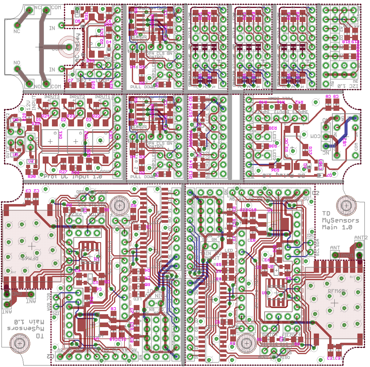
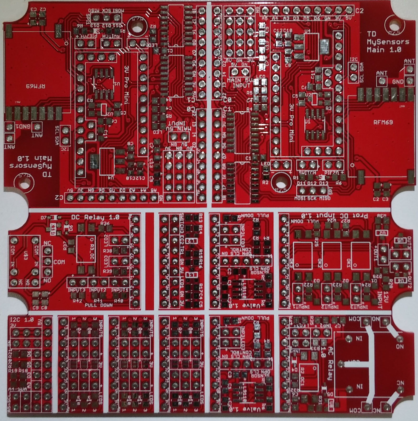
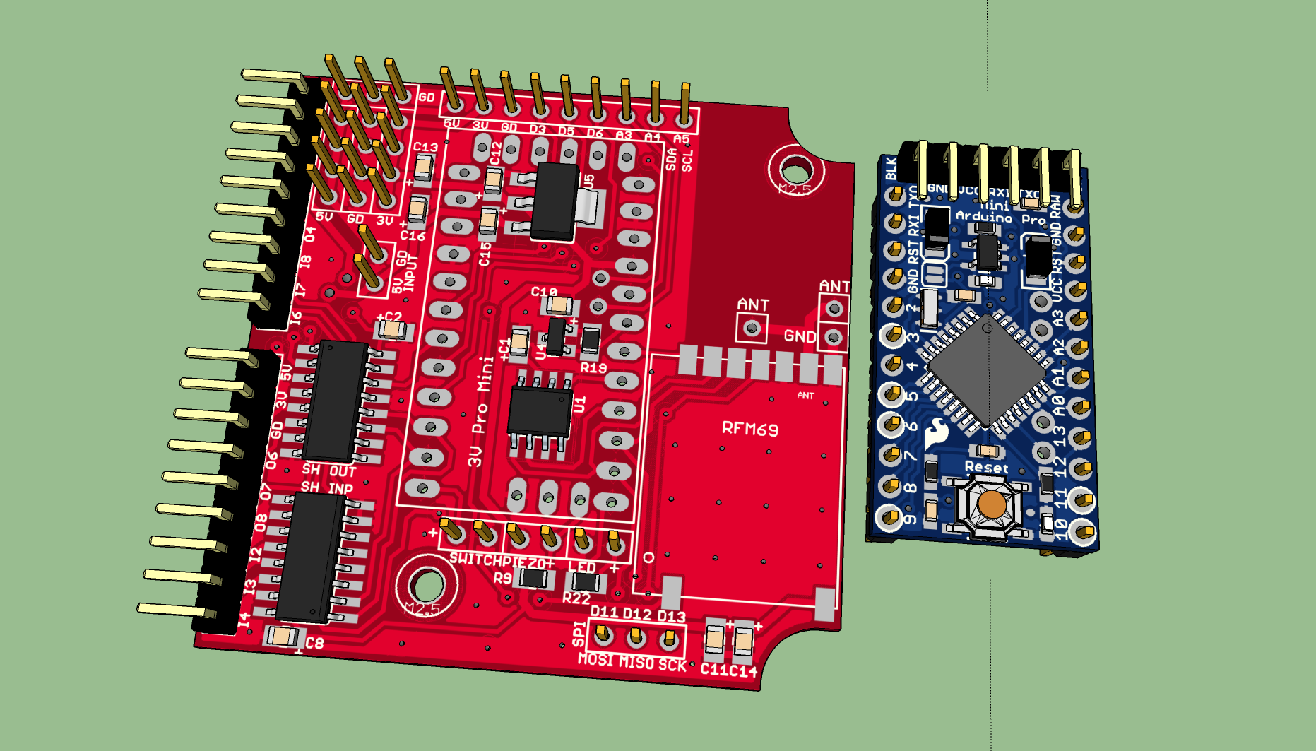
      Here's a 3D view of the main board with the Arduino removed:
      mother.png

      Each daughter board header has 5V, 3.3V, ground, 3 input pins, and 3 output pins. I've designed five different daughter boards so far. The first four fit in a single 5cm x 5cm package so I can get 10 copies of each for about $15. Other daughter boards are generally small enough that OSHPark is a viable source if I only need a few boards made (like for the car parking board).

      • Relay board. I'm using this to control simple switching (like the garage door opener) and AC loads (hot water recirculating pump).
        • 1 solid state opto-isolated relay with screw header with LED for AC loads
        • 2 switched transistors for simple connections
        • 3 sensor inputs with pull up resistors
      • Protected input board. I'm using this to trigger when external security cameras and motion sensors trip (they both operate on 12V signals).
        • 3 opto-isolator circuits for triggering on 12V lines
      • Valve/motor control board. I'm using this for articulated water valves for controlling leaks at the water heater, washing machine, etc.
        • L9110 motor controller with LED and valve open/closed sensors.
      • Generic LED/sensor board. This board adds pull up resistors on the inputs and LED resistors on the outputs so it can be used with the shift registers.
        • 3 sensor inputs with pull up resistors
        • 3 LED's with resistors
      • Car parking board
        • 3.3V<->5V level shifters for the distance sensor
        • Ultrasonic distance sensor
        • LED ring

      To give you an example of how this works, here are some of the builds I'm going to use:

      • Garage sensor
        • relay board for monitoring and controlling the garage door
        • parking board for LED parking sensor
        • could add a 3rd sensor board for temp, humidity, or air quality later
      • Water heater sensor
        • sensor board for monitoring water leaks
        • valve board for shutting off hot water intake
        • relay board for a hot water recirculating pump
      • Refrigerator and bathroom sensor
        • sensor board for monitoring water leaks
        • valve board for shutting off water to the ice machine or toilet
      • Washing machine sensor
        • sensor board for monitoring water leaks
        • valve board for shutting off the hot water
        • valve board for shutting off the cold water

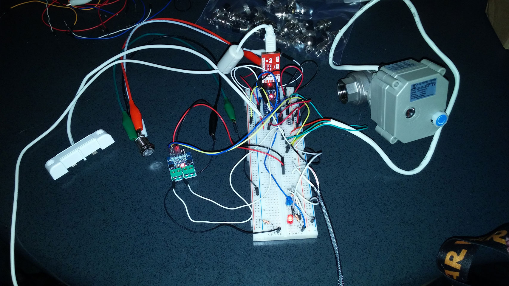
      I've finished all of the board designs and am now bread-boarding the schematics to make sure everything works properly before I put in my order. Once I get everything tested and confirm the boards work, I'll post the schematics and board files for anyone else that's interested. If you have any suggestions or comments, I'd love to hear them.

      posted in My Project
      TD22057
      TD22057
    • RE: Mother/Daughter board system

      Surprisingly, all of my circuits are working perfectly. I found one relay label that was swapped (NO/NC) and one jumper pad that wasn't very useful but other than that, all of the functionality is working. I have to admit I'm quite surprised there wasn't some serious problem somewhere given that this is my first non-trivial board design.

      When I started this design, I purchased a stereo microscope and it was fantastic. I'm no soldering expert by any measure but having the microscope (using the 5x lenses) made soldering all of the components very easy. After building 8 main boards and a bunch of daughter boards, I can now see why people invest in making a reflow oven for soldering.

      I'll be uploading the design files and schematics as soon as I clean up the BOM. Next up is cleaning up the software to drive everything and start on the case construction.

      Boards

      posted in My Project
      TD22057
      TD22057
    • RE: Water Leak Detection

      Here's another great leak "sensor": rope leak detector. The nice part about this is that it can cover a large area and it's basically white so it looks nice. I'm planning on cutting the 8 foot length up in to 15-20cm lengths to use in multiple locations.

      There are four wires in the sensor in the rope, 2 black, 1 white, 1 red. The only ones that matter are the black ones. Feed 5V to one of the black wires and attach the other to an analog pin. When dry, the pin reads about 20-30 (out of 0-1023 analog range). When wet, it will read anywhere from 60-150. That's not high enough to trip the digital HIGH value using digitalRead() so it needs to be hooked up to an analog pin to work properly.

      posted in Hardware
      TD22057
      TD22057
    • Eagle PCB software tips and tricks

      I just got my first large (for me) PCB order in and so I've spent a lot of time using the Eagle PCB design software over the last few months. I realize that many/most people are using KiCad since it's open source but I found Eagle first and did a lot of work in it before I saw KiCad so that's what I've stuck with. I thought it might be a nice idea to capture what I've learned about using Eagle effectively and see if anyone else had any tips to share.

      Project names

      Put a version number in the project name. I usually start with v1...vN as I'm iterating designs. Any time you start reworking something (routing, layouts, etc), save it to a new iteration. When you submit an order, move all the extra versions to a backup folder and rename the version you submitted to v1.0 and never change it again. If you need to edit something, create a v1.1 and edit that.

      Hot keys

      To get the maximum efficiency, use hot keys for everything. It's much faster selecting tools and toggling layers if you have keys set up instead of using the mouse. The most important set to me are the display keys (see F9-F12). They allow me to quickly toggle top and bottom layers and toggle polygon filling. It's annoying to set them up because you have to do it in the schematic editor and the board editor but it's worth it.

      The most useful ones are:

      • F9 shows both layers
      • alt-F9 shows just unrouted air wires
      • F10 shows just the top layer
      • F11 shows just the bottom layer
      • F12 fills polygons (ground planes)
      • alt-F12 unfills polygons

      Here are my keys:

      Key Action
      alt-b move
      alt-c copy
      alt-d delete
      alt-e net
      alt-f move
      alt-g group
      alt-i info
      alt-j junction
      alt-l label
      alt-m move
      alt-n name
      alt-q ripup
      alt-r rotate
      alt-s smash
      alt-t text
      alt-v via (board), value (schematic)
      alt-w route (board), wire (schematic)
      alt-z ratsnest
      F9 display 1 tname torigin tplace 16 bname borigin bplace pads via unrouted dimension tkeepout bkeepout trestrict brestrict drills holes milling; display 1 16 125
      alt-F9 display none unrouted
      F10 display top tname torigin tplace -bottom -bname -borigin -bplace -bkeepout
      F11 display bottom bname borigin bplace -top -tname -torigin -tplace -tkeepout
      F12 ratsnest
      alt-F12 ripup @;

      Libraries

      Build your own part library with the parts you'll use. That way you can find things faster and you know whether they work or not. Copy parts from eagle, sparkfun, and other online sources. You can find the library I've created for MySensors components at https://github.com/TD22057/Eagle-MySensors

      Grid

      For the schematic view, stick with 0.1 inch spacing since most of the library parts use that for the schematic symbol layouts (and NEVER use the alternate spacing). This insures wires will snap to the correct location and the connections get made. For the board view, metric or Imperial works. Since most of the parts I use have pins on 0.01 inch spacing, I use a grid with the major size 0.025" and the alternate size 0.00625 which seems to work well.

      Ground planes

      Use 0.012 isolation, 0.010 line width. The smaller line width allows the ground plane to flow between pads better. If you ever see a ground plane not going between a pad you think it should - it's probably the line width.

      Silk screen

      0.032, 15% is the smallest text size I would use on a board. That's readable (in good light) - but I usually prefer things to be larger than that. Once your board is done, smash all the parts to separate the text and parts, then position the labels in good locations. Add your own labels with the text command - make sure they're in the tPlace layer - that way the panelize ulp will duplicate them correctly.

      Scripting

      Eagle has a scripting language which I don't really understand. But - if you have any task that seems tedious (changing lots of items, spacing many components on a grid, etc), someone has probably already written a script to do it so search the web for Eagle scripts.

      Design Rule Checking (DRC)

      Obviously you need to run DRC often to make sure you haven't violated any rules. Download the DRC file from your manufacturer and use that. I normally copy and edit that file and make it more conservative and use that for my DRC run. The more conservative you can be, the less likely there are to be errors in the board when it's made.

      Viewing your board

      Use http://3dbrdviewer.cytec.bg/ to upload the board file for 3-d viewing. This can help visuallize how close things are together. In addition, you can download EagleUp and use it to export your board to SketchUp for 3-d viewing. Each part in your board will require a SketchUp object with the same name but they're pretty easy to find. This can really help visuallize how components will fit together.

      Ordering your board

      Before placing an order, run the renumber ULP - that will insure that parts are numbered in a reasonable order (so R12 isn't next to R1). Then adjust all the labels until you're satisfied.

      If you need to "panelize" a board (make duplicates of a single board in a larger board), you can do that. Close the schematic view and save the board to a new file. Run the eagle panelize.ulp - that will copy all the names from the tNames and tPlace names to a new layer. Then do a group, copy on everything and position the copy. Repeat as necessary. The problem with the copy is that each part gets a unique name which makes the labels wrong. But, the copied names in the new layer are correct so when you export the board for manufacture, select that layer instead of tPlace and tNames and the labels will be correct. See this panelize tutorial for more details.

      Be sure to download the CAM job from whatever board house you use (so far I've had great results from Elecrow) and run that to generate the gerber files for them.

      Boards larger than 10cm x 8cm

      The free version of Eagle limits boards to 10cm x 8cm. If you can split your order into smaller pieces (say two 10cm x 5cm or four 5cm x 5cm boards), you can use eagle-brd-merge to merge multiple board files. It takes in an offset and rotation for each board and writes out a new board file with the merged result. You won't be able to edit anything outside the 10x8 cm area but it works great for combining multiple boards into a single panel.

      posted in Hardware
      TD22057
      TD22057
    • Over the air (OTA) bootloading update tutorial?

      Has anyone done a write up that explains what the requirements are for using OTA bootloading updates? I'm closing in on a custom PCB board design and may want the option to support that in the future. I've looked at some existing boards people are designing and most seem to add a flash memory chip to support OTA but I haven't found much information beyond that. Some questions:

      1. What are the software and hardware requirements in the gateway for OTA?
      2. What are the software and hardware requirements in a sensor for OTA?
      3. Is a custom bootloader needed in the sensor?
      4. I assume that firmware downloads are targeted at a specific sensor ID right?
      5. How is an OTA update initiated? By the controller? If so, which controllers support it?

      Thanks in advance.
      TD

      posted in General Discussion
      TD22057
      TD22057
    • RE: Mother/Daughter board system

      Update: I settled on an SPI based shift register system and received and tested those parts (they will require an update to the RFM69 library to use SPI transactions but we should do that anyway). I finished testing all of my schematics on a breadboard, fixed several errors, and submitted my PCB order this morning with Elecrow for 10 board of 10 cm x 10 cm. I was able to fit 2 main boards and 10 child boards on a single panel so that's 120 different boards for $25. I ended up creating the following 7 different child boards to use in the system:

      • valve board (see first post)
      • protected input board (see first post)
      • sensor board (see first post)
      • parking board (see first post)
      • AC relay board (higher amperage/power relay for large loads)
      • DC relay board (5V DC relay for small loads)
      • I2C sensor board

      Once I get the boards in and test them, I'll post the raw boards and schematics (or ping me if you want to see them now) in case anyone is interested. Just because it's cool, attached is an image of the final board submission.image.png

      posted in My Project
      TD22057
      TD22057
    • RE: Safe In-Wall AC to DC Transformers??

      You don't really have to buy anything - lots of things will work to keep the temperature down. A wet paper towel wrapped around the fuse or submerge it in a small cup of water (easy for through hole components when the board is upside down) or wrap with 2 wet sponges and some rubber bands, etc etc.

      posted in Hardware
      TD22057
      TD22057
    • RE: Mother/Daughter board system

      Yeah! Boards have arrived. I used elecrow.com and ordered 10 boards for $25. They shipped 14 and they arrived (California) in 16 days. Everything looks good so far. I probably should switch to a larger silk screen font for some of the labels but so far all the footprints seem to be correct. Next up is to start cutting the boards apart and start soldering...
      0_1453395171426_20160121_083157.jpg

      posted in My Project
      TD22057
      TD22057
    • Some simple asynchronous Arduino classes

      I wanted to share some of the classes I've been using for my MySensor modules. I've been making some fairly complicated sensors (boards with a lot of things going on - see my mother/daugter board system) and I have found that these classes to be very useful. They're all fully commented and include test sketches. They're designed around two main principals:

      • Asynchronous operations. There are no delay calls anywhere. Each class maintains it's own state and behaves accordingly. This allows me to combine many different items and use them all without worrying about how they interact with anything else.

      • Hardware abstraction. Each class has a very similar API in which the hardware specific information is set in the init() function called in the the setup. After that, all the interaction is via state change ("turn on", "blink 5 times", "sensor triggered", etc). In my board system, I connection these things via direct Arduino pins (some digital, some analog, some analog only A6/A7) and shift registers. This abstraction allows be to use the same logic code regardless of how the hardware is actually connected.

      The basic idea is that:

      • setup(): initializes the hardware (pins, etc) and state
      • loop(): poll each object with a callback function to look for changes
      • callback(): handle the state change

      I've found that I really like this type of API. All of the hardware configuration is in setup() and all of the state changes (what happens) is in the callback. I've found that this makes the code easier for me to debug and much easier for me to understand (when I come back and look at it 6 months later) since the role of each function is clearly defined. On the output side, the DigitalOutput class allows me to turn things on for different amounts of time (turn a relay on for 5 seconds) while various LED's are blinking at different rates with very simple code. It's not the most size efficient code - but I've never found that to be a problem for my builds and the ease of use and clarity of intent is more important to me.

      • DigitalInput: On/Off inputs (switches) with either HIGH or LOW
        active, optional debouncing, and support for digital pins, analog only
        pins (A6/A7) and shift registers.
      • DigitalOutput: On/Off ouputs (LED's, relays) including blinking.
      • MedianFilter: N sample running median filter.
      • Sonar: Ultrasonic snsor.
      • Timer: Repeating (num or infinite) periodic triggers.
      • Valve: 5 wire articulated valve control

      The repository is here: https://github.com/TD22057/TD-Arduino-Core
      A good, long'ish example using several different classes is: https://github.com/TD22057/TD-Arduino-Core/blob/master/Valve/tests/leak_sensor/leak_sensor.ino

      Feel free to use these if you find them helpful and any comments or suggestions are welcome.

      posted in Development
      TD22057
      TD22057
    • RE: Water Leak Detection

      We just had a water heater fail so I'm in the middle of exactly the same project. I'm waiting on aliexpress orders for all my sensors but I'm planning on starting with multiple leak detectors in each bathroom (under sinks and toilets), the laundry room, the kitchen, and the water heater. I looked at all of those sensors and didn't like any of them. Right now, I'm going to try these: www.ebay.com/itm/231594180289
      which have 2 contacts spaced a little bit apart. They seem to work fine so far but I haven't tried hooking them to an arduino yet. I'm hoping I can find them for cheaper before I place my final order (I need about 12 of them).

      For stage 2 of my plan, I'm going to install actuated valves that will turn off the water when a leak is detected. Valves are about $30 and work on 5V from this store (click their store link for lots of options): http://www.aliexpress.com/store/product/2-Way-1-2-Brass-Motor-Valve-with-manual-override-DN15-DC5V-5-wires/414681_1695915390.html
      I'm also going to use a H-bridge module to allow reversing the valve w/ 2 pins: http://www.aliexpress.com/item/5pcs-lot-H-bridge-Stepper-Motor-Dual-DC-Motor-Driver-Controller-Board-For-Arduino-HG7881/1927732289.html

      posted in Hardware
      TD22057
      TD22057
    • RE: Is MQTT Necessary? or, Use Case for MQTT?

      The biggest thing MQTT adds for me is abstraction. The RF messages MS uses get converted to MQTT which the controller (and other things) understands. This means the controller only needs to understand MQTT, not MS. And I can merge lots of different sensor sources into a single system by converting them all to MQTT.

      As a trivial example, I have three sources for temperature data in my house. 1) MySensors nodes, 2) two WIFI thermostats, 3) several Acurite wireless weather sensors. All of those get converted to a single, standard format MQTT temperature messages. So it doesn't matter what the hardware is, if I want to graph/see/store temperature data, I just need to know the MQTT message format.

      posted in Controllers
      TD22057
      TD22057
    • RE: Water Leak Detection

      It's ALIVE!!! Ok - not really, but I've finished my first milestone. I've wired up a bread board prototype with several status LED's, a leak sensor, an override switch (for clearing a "leak"), the motor controller, and motorized valve. I'm very impressed with the valve so far - it works on 5V, doesn't use much current (~50mA), it cuts power and soon as the limit is hit, and the status sensors are a great feature. Since the valve is working so well, I've ordered more and need to try this with powering 2 valves at one time from 1 set of Arduino pins (no reason to think this won't work since they're just tripping a relay) which I need for my washing machine leak sensor.

      I've finished V1 of the sketch code including LED, Switch, and Valve classes which handle all the state changes. The valve code includes time outs for how long power should be applied as well as a duty cycle to not overheat the H-bridge (it doesn't seem to get hot at all so far). The valve also reports state changes (closed, closing, opened, opening) so the LED's be set to can light or blink accordingly.

      I haven't tied the code into MySensors yet but that's a trivial addition now that the core logic is working. I have some RFM69W radios arriving tomorrow so that will be the next addition.

      Here's my bread board - not because it's particularly interesting, but just because I'm excited that the firmware is working so well and want to share 😃.

      20150828_153929_2.jpg

      posted in Hardware
      TD22057
      TD22057
    • RE: Safe In-Wall AC to DC Transformers??

      FYI: Here's an emissions test of the HLK-PM01. I don't have any experience with this sort of thing so I'm not sure what to make of the results:
      https://skippy.org.uk/quick-look-at-the-hlk-pm01/

      posted in Hardware
      TD22057
      TD22057
    • RE: Yet another PCB to address (nearly) all Arduino pins

      You can find Eagle parts for M2, M2.5, M3 drill holes with tight and loose clearance in my Eagle parts library. I created the parts from this blog page.

      posted in Hardware
      TD22057
      TD22057
    • RE: Parking Sensor

      @Dan-S. said:

      Has anyone done that yet?

      Not yet, but I've got plans, big plans 🙂 - I'm working on a leak detector now but when that board is done, I'm going to build an "ultimate garage" PCB that will have the the parking LED, distance sensor, temp/humidity, garage door location sensors, garage door open/close relay, and will automatically close the garage door after a timeout unless a button is pressed.

      Here's the way I think about the parking problem: the car moves through 3 different areas: 1) entering garage (not safe), 2) safe to park (far enough in, but not too far), 3) danger - too far. But how do you know what sensor values those correspond to? Especially since mounting the sensor in different areas, at different angles, and with different vehicles will change those values. So if you hold down a button on the sensor, it puts it into config mode. Move the car to the start of the safe area, and push the button to record that sensor reading. Then move the car to the end of the safe parking area and push the button again to record that sensor reading. Then have the software dynamically update the LED ranges to respond to those sensors. Something like: in area 1), illuminate more and more LED's as the car moves through the area. When the car hits area 2), flash the ring green 3 times, then fully illuminate all LED's in green. As the car moves through area 2), decrease the number of LED's illuminated until it hits area 3) where all the LED's flash red.

      posted in My Project
      TD22057
      TD22057
    • RE: Help me choose smd components from mouser

      Look at the filters - there is one for "case code-in" and one for "case code-mm". So if you pick 0603 in "case-code-in", you get a normal 0603 part (metric 1608). If you pick 0603 in "case-code-mm", you'll get the metric 0603 (imperial 0201).

      FYI I have ordered a lot 0805 cap's and resistors from this seller on aliexpress ($2-3 per 100) and haven't had any problems with them yet.

      In Eagle 0603 is going to be the imperial 0603 part.

      posted in Troubleshooting
      TD22057
      TD22057
    • RE: Sensor to Gateway protocol documentation?

      I'm curious why you're against having a gateway. One of the good reasons to use one is that the RPI is not a real time OS and has a non-trivial chance of losing radio messages since the process to read from the radio may or may not be running while the messages come in. The more applications you start on the pi, the more likely you'll be too lose messages which will be frustrating and hard to debug, especially since it will be intermittent. A gateway is a cheap, easy way to avoid this.

      If you read the docs http://www.mysensors.org/download/sensor_api_15, the library API is the MyMessage class. The class is the protocol. For an example (using v1.5), look at MySensor::sendWrite() and you'll see it calls radio.send( &message, ... ) so it's sending the message class as the data over the radio link.

      posted in Controllers
      TD22057
      TD22057
    • RE: Water Leak Detection

      More updates: The water sensors I posted before work fine. I didn't realize that they aren't a simple contact switch - there is some circuitry inside them so they are directional and do require 5V. I also received a valve today so I have everything I need to build a prototype. Since I need 8 of these for my house (3 bathrooms, laundry, water heater, kitchen), I decided to make a custom PCB so I've been learning how to do that this week. I bought a sample box to use which had dimensional drawings so I could size a PCB board to fit. I'm going to try and make a single board for all my cases which will allow 2 valves to be controlled and have 3 water sensors.

      Here's a couple of pics of my current schematic and board layout. The J boxes are JST style female connectors and motor controller is taken from the HG7881 module documentation. I've also created a small Eagle PCB library for all the components including the ProMini clone pad layout which is a bit different than the standard ones. I'm not going to try and fab them until I get the box in and can check my dimensions. Once I have a working breadboard setup for this, I'll start a new thread to get any feedback on the design.
      Schematic.png
      Board.png

      posted in Hardware
      TD22057
      TD22057
    • RE: Mother/Daughter board system

      So it turns out the "standard" input shift register that everyone uses in Arduino examples (SN74HC165) doesn't work on the SPI bus because it never puts MISO into high impedance. It can be fixed with another chip (single gate, 3 state chip). Instead, I found an input shift register that is designed to work on SPI (74HC589). I've got those on order now and will try it out on the breadboard before ordering any real boards.

      I've been having fun w/ EagleUp and SketchUp - here is a view of my main board with three daughter cards installed in it. The bare pins are the inputs and output jacks which will go to the external connectors (power, sensor jacks, valve controls, etc), LED's, and switches mounted in the case. I have to admin, seeing the resulting board in 3D is just extremely cool 🙂 🙂

      Mother 7.png

      posted in My Project
      TD22057
      TD22057
    • RE: [security] Introducing signing support to MySensors

      @Anticimex - thanks for this. I finally got around to enabling signing on everything while I was testing out my new board design. I followed your schematic from your board design when I built mine and I just went through the instructions to configure the crypto chip and everything went smoothly. Thanks for the work and the good instructions!

      posted in Development
      TD22057
      TD22057
    • RE: RSSI and TX power of RFM69HW

      Searching RFM69.cpp shows there is an rssi variable already being defined and a RFM69::readRSSI() method available. Seems like a trivial mod to expose that into the public API of the MyTransportRFM69 class. There is also a readTemperature() method on RFM69 - I wonder if that could be used as a temp sensor for free? I'm waiting on my RFM69 radios to try them out - I'll add those methods to the class and give them a try when mine come in.

      posted in Hardware
      TD22057
      TD22057
    • RE: Monitor a irrigation status

      Yes - but you have to protect the arduino from that high voltage. Best way is with a small optocoupler chip (I use EL817 chips which you can get for practically nothing). There is an excellent explanation in the first answer on this post on stackExchange. You may have to adjust the resistors because of the higher voltage. I've included the schematic below (it's a good idea to read the answer though).lp5m2.png

      posted in My Project
      TD22057
      TD22057
    • RE: Change: MY_RFM69_FREQUENCY to MY_RFM69_BAND

      The RFM69 library from lowpowerlab (which MS has cloned) has a setFrequency() method which is almost the same as the one @lafleur posted above. It should be available in MS via accessing the RFM69 object. My understanding was it was used for tuning the network to avoid interference or in freq hopping applications.

      posted in Development
      TD22057
      TD22057
    • RE: Using mysensors for alarm build?

      I think it's a great idea. Who cares whether it's the perfect security or not - it's a useful and fun project to build.

      I'm planning on something like this in the long term (tons of other projects first and I already have an Ademco alarm w/ hardwired sensors everywhere). There are lots of ways you could build an alarm system. You could have an Arduino serial gateway passing sensor messages to a Raspberry Pi and then code up the alarm logic in any language you like on the pi (Python is much easier than C). Since the pi has internet access, it can send emails and run a web server to show alarm status. Or for hardwired alarms without MySensors, a pro-mini and a few input shift registers is probably enough to run a complete alarm system. Or for a MySensors (wireless sensors) build, you could buy an Arduino Mega and put the alarm code in that.

      Remote keypads could either be wireless w/ MySensors messages (ok) or wired with serial or I2C communication (better). I'd love to have a Mega with one of the Itead Nextion touch screens for my alarm keypads. Maybe with a motion sensor that only turns on the display when you're near it. Then the keypad could double as a weather display, general my sensors controller (lights, etc) as well as an alarm keypad.

      posted in Hardware
      TD22057
      TD22057
    • RE: Mother/Daughter board system

      I've finished soldering the first batch of boards and things look pretty good so far. I had one diode footprint that was wrong but it was easy to fix and a couple of soldering errors that were also fixable. In hind sight, I think putting the power supply and other IC's under the arduino is a mistake - I should have moved them to the back of the board. If there is anything is wrong with a joint, it's impossible to get to for diagnosis and reworking. Here's a glamour shot of the mother and daughter boards:

      0_1453486735703_IMG_1813.jpg

      posted in My Project
      TD22057
      TD22057
    • RE: PCB and 3D print companies

      Check http://pcbshopper.com/ for prices and reviews. I got very good results from Electrow for my last order.

      posted in Enclosures / 3D Printing
      TD22057
      TD22057
    • RE: Serial Gateway Between Two Pro Mini's - More Info?

      Try the MockSensors sketch one of the minis. It sends fake sensor data at whatever rate you want (you'll have to edit the sketch to pick a couple of dummy values). Leave the serial gateway on one of them and plug that into the computer. You should see sensor data arrive at expected rate if things are working.

      posted in Hardware
      TD22057
      TD22057
    • RE: MQTT: Can somebody explain Gateway to a beginner?

      https://github.com/mysensors/Arduino/blob/master/libraries/MySensors/examples/MQTTGateway/MQTTGateway.ino

      In that gateway code is the TCP_IP and TCP_PORT the external broker IP and port numbers? The comments say those are the static IP and a port to listen on. I read that as saying it's the static IP of the gateway and the port for the broker to listen on but perhaps they mean the remote IP/Port of the broker to connect to.

      posted in General Discussion
      TD22057
      TD22057
    • RE: US decora style wall switch

      Very interesting designs @enterprised and @dbemowsk. I've also been working on my own version of decora switch and relay system. It's designed to use empty keystone switch plates with 1, 2, or 3 switches and uses keystone jack fillers as the switch covers so they look almost commercial. It's a 3 PCB system. The front PCB has the switches, LED's, reset button, CPU, and an RFM69 or NRF radio. The middle PCB has a MeanWell IRM-02 or HLK AC->DC converter (with fuse, thermal fuse, and varistor), a replaceable fused 10A AC relay with opto-coupler isolation, 5V and 3.3V rails and a 2 wire temperature probe to measure the temp of the PSU module. The back PCB is just a cover to insure no sharp solder points are in an electrical box. I decided that since this will be in my walls, I would only use name brand parts (from digikey and mouser) on the high voltage side which increases costs but should reduce the risk of fire (or at least make me feel better).

      I've designed the PCB and checked them over but we're in the middle of buying a house and moving so I haven't ordered any yet. Here's the 3D rendering of the PSU and CPU boards together and a one of the PSU board.

      0_1484794975291_combined.png
      0_1484794989118_psu.png

      posted in My Project
      TD22057
      TD22057
    • RE: Safe In-Wall AC to DC Transformers??

      One more note: There is also an HLK PM03 which outputs 3.3V.

      posted in Hardware
      TD22057
      TD22057
    • External connector options?

      What are people using for external sensor connectors? I'm planning on building multiple leak detector sensors and having each one support 3 leak sensors (2 wires) and 2 articulated valves (5 wires) along with a jack for an external power supply (2 wires). I'd like to have a connector on the outside of the sensor box that holds the arduino for each connection that is small, looks nice, is easy to use, and can't be confused (don't plug the power supply into the sensor input). Here are some of the options I've found so far. Generally I like the round connectors better since it's easier to mount a round jack (using just a drill bit) vs having to cut a square hole in a plastic box. Any other ideas I'm missing?

      Micro USB: nice for power since micro usb cables are easy to come by. Hard to cut a square hole for mounting.

      4 Pin JST plug: Maybe glue them flush to the outside of the box, don't look very nice.

      2 wire JST Cheap, stick out a lot from the box, harder to mount?

      12mm XLR plug: Easy to mount, various numbers of pins, locking, but somewhat large.

      5mm locking power plug Easy to mount, locking, small, good for 2 wires. Or the non-locking version

      I also looked at headphone style jacks butthey short across the connections when they're inserted and removed and can be noisy if rotated which I don't like at all.

      posted in General Discussion
      TD22057
      TD22057
    • RE: Yet another PCB to address (nearly) all Arduino pins

      Looks very cool.

      The immediate thing I noticed is that there should be bypass capacitors on all the IC's. So a 0.1uF cap on the crypto and flash memory chips. And if you have caps in the schematic, they should really be wired with the chip they go with. I noticed there are a few caps in the schematic that are by themselves (just vcc/cap/gnd) - if those are bypass caps, it helps a lot to have them shown in the schematic with the IC they go with. That makes it clear that they need to be on the board next to the IC and not at an arbitrary location.

      Mounting holes for screws might also be a good idea.

      posted in Hardware
      TD22057
      TD22057
    • RE: RFM69W voltage dividers?

      Thanks! Out of curiosity, why is the I2C level shifter better for the radio than non-I2C versions I was looking at?

      posted in General Discussion
      TD22057
      TD22057
    • RE: Safe In-Wall AC to DC Transformers??

      @TD22057 said:

      I have a question... referring to the first post, why is the varistor after of the fuses? I thought it was there to protect against surges in the AC lines which would makes me think that the varistor should be before the fuses. Thoughts?

      I answered (some what) my own question via Google. Here's a quote from an electronics site:

      Fuse upstream of the MOV, but don't expect it to save the MOV. It will prevent your house from burning down after the MOV partly shorts and sits there glowing red hot.

      So it seems like the original post is correct on the order.

      posted in Hardware
      TD22057
      TD22057