Look here under Valve: https://github.com/TD22057/TD-Arduino-Core
T
TD22057
@TD22057
Posts
-
Water Leak Detection -
Safe In-Wall AC to DC Transformers??You don't really have to buy anything - lots of things will work to keep the temperature down. A wet paper towel wrapped around the fuse or submerge it in a small cup of water (easy for through hole components when the board is upside down) or wrap with 2 wet sponges and some rubber bands, etc etc.
-
Water Leak Detection@mars000 said in Water Leak Detection:
@TD22057
I can't seem to work out how the water sensor functions - i notice you wired it to 5V on red and black to D4, but is there a trick in terms of how it works ?
I assume you are reading the D4 pin in your code ? Could you pls help out/share your code ?
How you finding the reliability of the sensor and value ?Honestly - I don't remember. Re-reading the thread, I believe they worked fine but that 5V was required. Try hooking them up to an analog pin and reading the value there. They might be not be passing enough voltage to trigger a digital reading. I actually never deployed the design above - I switched to a more modular design and used the rope sensors shown above. I haven't had any problems with the valves - of course they don't cycle at all since I don't have any leaks, but they work when I test them.
-
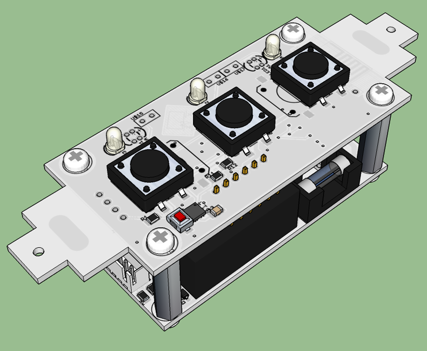
US decora style wall switchVery interesting designs @enterprised and @dbemowsk. I've also been working on my own version of decora switch and relay system. It's designed to use empty keystone switch plates with 1, 2, or 3 switches and uses keystone jack fillers as the switch covers so they look almost commercial. It's a 3 PCB system. The front PCB has the switches, LED's, reset button, CPU, and an RFM69 or NRF radio. The middle PCB has a MeanWell IRM-02 or HLK AC->DC converter (with fuse, thermal fuse, and varistor), a replaceable fused 10A AC relay with opto-coupler isolation, 5V and 3.3V rails and a 2 wire temperature probe to measure the temp of the PSU module. The back PCB is just a cover to insure no sharp solder points are in an electrical box. I decided that since this will be in my walls, I would only use name brand parts (from digikey and mouser) on the high voltage side which increases costs but should reduce the risk of fire (or at least make me feel better).
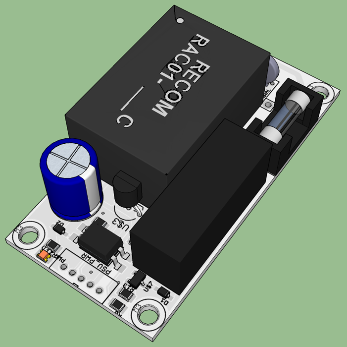
I've designed the PCB and checked them over but we're in the middle of buying a house and moving so I haven't ordered any yet. Here's the 3D rendering of the PSU and CPU boards together and a one of the PSU board.
-
Double click | Hold for buttonsI have short and long press status reports on my switch class here. There are example sketches one directory up in the tests area. Double click gets more complicated because you have to decide are you going to delay reporting the press/release from the first click until enough time has passed for it not to be a double click? Or do you report the press/release from the first click, and then report a double click? I'd be surprised if there aren't a lot of arduino double-click switch examples around...
-
Rfm69 and that pesky antenna@nagelc said:
I have tried this antenna with the RFM69:
YAGEO ANT1204F005R0915A
http://www.newark.com/yageo/ant1204f005r0915a/antenna-chip-915mhz-50-ohm-1204/dp/38X6113?ost=ANT1204F005R0915A&selectedCategoryId=&categoryNameResp=All%2BCategories&searchView=table&iscrfnonsku=falseThat looks very promising. But I have no idea how to design or tune the matching circuit called for in the data sheet. Any thoughts?
I've used these type of small helical antennas with good results.
-
💬 MDMSensor "Multisensor"Very cool. What kind of connector are you using to connect to the programming pads?
-
💬 Mini Relay BoxVery cool. Would you mind adding a pdf of the schematic?
-
Safe In-Wall AC to DC Transformers??@TD22057 said:
I have a question... referring to the first post, why is the varistor after of the fuses? I thought it was there to protect against surges in the AC lines which would makes me think that the varistor should be before the fuses. Thoughts?
I answered (some what) my own question via Google. Here's a quote from an electronics site:
Fuse upstream of the MOV, but don't expect it to save the MOV. It will prevent your house from burning down after the MOV partly shorts and sits there glowing red hot.
So it seems like the original post is correct on the order.
-
Safe In-Wall AC to DC Transformers??I have a question... referring to the first post, why is the varistor after of the fuses? I thought it was there to protect against surges in the AC lines which would makes me think that the varistor should be before the fuses. Thoughts?
-
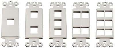
US decora style wall switchIf getting the laser cut blank doesn't work out, another option you could consider is using pre-cut keystone plates. It's probably possible to modify a blank keystone jack by cutting the mounting tabs off and have it sit flush or a little proud of the plate and use that to press a switch on the pcb behind it.

-
US decora style wall switchThat looks fantastic! I looked at the capacitive solutions and while they're neat, I don't like them from a user interface perspective. I want tactile feedback in a switch - a rocker would be even better but this is a close second. It would be nice if you could take those of us who use RFM69's into account if that isn't too difficult.
You might want to look at the SwitchMote for packaging and board ideas. Another thought: Just my opinion but I think it would look nicer if it was symmetrical. Could the LED's be moved into the center between the switches?
-
PCB and 3D print companiesCheck http://pcbshopper.com/ for prices and reviews. I got very good results from Electrow for my last order.
-
PCB supportThere are standards for PCB hole sizes. You can find Eagle parts for M2, M2.5, M3 drill holes with tight and loose clearance in my Eagle parts library. I created the parts from this blog page.
-
Smart Light Switch 220vHere's the data sheet I have for those: G3MB solid state relay.pdf
-
Is MQTT Necessary? or, Use Case for MQTT?@Dwalt said:
How are you converting the Acurite sensors to MQTT?
The Acurite Bridge is a 433MHz receiver that reads any Acurite sensors and posts them to the Acurite web site using a simple HTTP call. I have it connected through a USB ethernet dongle to a Raspberry Pi with the dongle bridged to the main network. I have a script which runs tcpflow to intercept that traffic and send it to some simple Python scripts I wrote which convert the data to MQTT. There are instructions here - they're out of date but give you the basic idea. So it's basically a man-in-the-middle attach against the bridge traffic. Let me know if you want more information - I have the code in git but haven't pushed it up to github lately.
-
Is MQTT Necessary? or, Use Case for MQTT?The biggest thing MQTT adds for me is abstraction. The RF messages MS uses get converted to MQTT which the controller (and other things) understands. This means the controller only needs to understand MQTT, not MS. And I can merge lots of different sensor sources into a single system by converting them all to MQTT.
As a trivial example, I have three sources for temperature data in my house. 1) MySensors nodes, 2) two WIFI thermostats, 3) several Acurite wireless weather sensors. All of those get converted to a single, standard format MQTT temperature messages. So it doesn't matter what the hardware is, if I want to graph/see/store temperature data, I just need to know the MQTT message format.
-
💬 My MySensorized Wall-plug@scalz said:
@m26872 oki! same bad luck things happens to me sometimes ;)
Finally I have looked at my cheap wallplugs and it seems smaller than yours...so more difficult to fit something in mine.
I have few of these box that I bought for this purpose too (and still empty!) : http://www.tme.eu/fr/details/cp-z-27_j/boitiers-pour-alimentations/combiplast/
Bigger..and maybe less interesting/looking nice than buying a kit of 3 wallplug. but maybe easier to make something "standard" as it can be bought from tme.Those look very nice. I wish I could find a US version of that box somewhere.
-
Glass break sensor?Another write up on resistors dividers and opto-couplers: http://electronics.stackexchange.com/questions/43498/how-can-i-use-a-12-v-input-on-a-digital-arduino-pin
I've used optocouplers in the past without any problem. They can be purchased for practically nothing on aliexpress. In either case it's important to check the voltage on the signal line ahead of time to really see what the sensor is putting out.
-
Why continue to use NRF24L01?@neech said:
TD22057, I love this idea. However, how are you going to power the ESP? I'd like to do the same thing but don't want to take the thing out to replace a battery. I also don't want to try and fit a 5v or 3.3v power supply in there...just curious if you thought of that yet.
Search for HLK-PM01 - there are a bunch of threads on how to power from 120/240V mains.