@sundberg84 Thankyou
Woodside
Posts
-
💬 Easy/Newbie PCB for MySensors -
💬 Easy/Newbie PCB for MySensors@sundberg84 The only file type I can find on openhardware.io for the schematic is a pdf. DIPTrace is a schematic and PCB layout tool and uses .sch format for the schematic files. It cannot import a schematic layout from a pdf.
I was hoping to use DIPTrace to update the schematic for my projects using the EasyPCB and then transfer the result onto the board.
-
💬 Easy/Newbie PCB for MySensorsIs there a .sch version of the schematic that I can import into Diptrace? I can only find a .pdf
-
Nano losing program codeI have an irrigation system with an arduino nano (clone) driving 4 relays that control the irrigation valves. This has been working the vast majority of the time for 2 years.
However once every few weeks, the nano loses its program code.
The nano and relays are mounted outside in a waterproof box. They are mains powered and turned on at the same time as the water butt pump. If I initiate a valve opening within sight of the gateway (indoors) I can tell the relay node is not working as there is no initial handshake visible on the gateway leds.
When I go to reload the program into the relay node, the red onboard led is flashing every second as if it is running the 'blink' code. There is nothing being output from the serial monitor.
Controller: Vera 3
MySensors Lib version: 2.3.0******************************* * * REVISION HISTORY * Version 1.0 - Henrik Ekblad Relays remembered previous state at start up * Version 1.2 - M Young Relays reset to off at startup * Update latest version of software in variale 'VERSION' below * * DESCRIPTION * Example sketch showing how to control physical relays. * http://www.mysensors.org/build/relay */ //Set node id manually out of the range of the soil moisture sensors #define MY_NODE_ID 100 // Enable debug prints to serial monitor //#define MY_DEBUG // Enable and select radio type attached #define MY_RADIO_NRF24 //#define MY_RADIO_RFM69 // Enable repeater functionality for this node #define MY_REPEATER_FEATURE #include <MySensors.h> #define RELAY_1 3 // Arduino Digital I/O pin number for first relay (second on pin+1 etc) #define NUMBER_OF_RELAYS 4 // Total number of attached relays #define RELAY_ON 0 // GPIO value to write to turn on attached relay #define RELAY_OFF 1 // GPIO value to write to turn off attached relay #define VERSION "V1.3" void before() { for (int sensor=1, pin=RELAY_1; sensor<=NUMBER_OF_RELAYS; sensor++, pin++) { // Then set relay pins in output mode pinMode(pin, OUTPUT); // Set relay to last known state (using eeprom storage) //digitalWrite(pin, loadState(sensor)?RELAY_ON:RELAY_OFF); //Set relay to always be off at startup digitalWrite(pin, RELAY_OFF); } Serial.println(F("Relay Actuator - "VERSION));//F means use program memory, dont copy to RAM } void setup() { } void presentation() { // Send the sketch version information to the gateway and Controller sendSketchInfo("Relay Actuator", VERSION); for (int sensor=1, pin=RELAY_1; sensor<=NUMBER_OF_RELAYS; sensor++, pin++) { // Register all sensors to gw (they will be created as child devices) present(sensor, S_BINARY); } } void loop() { } void receive(const MyMessage &message) { // We only expect one type of message from controller. But we better check anyway. if (message.type==V_STATUS) { // Change relay state digitalWrite(message.sensor-1+RELAY_1, message.getBool()?RELAY_ON:RELAY_OFF); // Store state in eeprom saveState(message.sensor, message.getBool()); // Write some debug info Serial.print("Incoming change for sensor:"); Serial.print(message.sensor); Serial.print(", New status: "); Serial.println(message.getBool()); } }Why would the nano lose its code?
Is there any method of diagnosing the cause?
-
Water flow meter for hozelock hose pipe.I came across this recently that may be suitable, with appropriate hozelock adapters?
-
Child X not present in node XI had exactly the same issue on Vera after upgrading my Gateway to 2.3.0.
After upgrading the Gateway I had to add each node back individually. Four of my nodes had manual Node_IDs assigned and one had auto Node_ID. As it happened I added Nodes 1 and 2 first which were manual and then added the auto node. It automatically assigned node 3 as the next available node.
I then added node 4 (manual) successfully but Node 3 would only add one of its child nodes.
The problem was that the auto node had added Child ids of 1 to 4. When I added the manual node 3, it correctly added child id 0 but could not add the second child as child 1 had already been allocated by the auto node.
I couldn't find any error messages to indicate the problem.
I eventually found this LUA code which showed all the devices with the node and child ids that had been assigned.
I deleted the auto node, changed the sketch to set the node manually and re-added it. Deleted node 3 and re-added and everything was fine.
I realise this was for a Vera system, but the real problem was the order of adding nodes and probably more importantly mixing nodes with manual and auto node assignments in the same mesh.
I will be using manual node assignment for all nodes going forward!
-
What do the Error led flashes mean?Thanks both.
I will try the gateway with version 2.2.0 first.
-
What do the Error led flashes mean?@Yveaux That is useful information, thank you.
Rather than trying to count the flashes to work out what is going on, can I output the error message(s) to the serial monitor?
@gohan Attached is the serial log from startup and some successful commands from Vera to turn the relays on and off. I cannot see any errors? When the Gateway starts up there are about 29 flashes of the error led (difficult to count exactly).
For a successful relay on or off there are two error flashes. According to the MyIndication.h extract from @Yveaux, corresponds to 'Failed to transmit message'. But the relay switches correctly and there are no transmit errors in the serial log.:confused:
0;255;3;0;9;MCO:BGN:INIT GW,CP=RNNGA--,VER=2.1.1 0;255;3;0;9;TSM:INIT 0;255;3;0;9;TSF:WUR:MS=0 0;255;3;0;9;TSM:INIT:TSP OK 0;255;3;0;9;TSM:INIT:GW MODE 0;255;3;0;9;TSM:READY:ID=0,PAR=0,DIS=0 IP: 192.168.0.40 0;255;3;0;9;MCO:BGN:STP 0;255;3;0;9;MCO:BGN:INIT OK,TSP=1 0;255;3;0;9;TSF:MSG:READ,3-3-255,s=255,c=3,t=7,pt=0,l=0,sg=0: 0;255;3;0;9;TSF:MSG:BC 0;255;3;0;9;TSF:MSG:FPAR REQ,ID=3 0;255;3;0;9;TSF:CKU:OK,FCTRL 0;255;3;0;9;TSF:MSG:GWL OK 0;255;3;0;9;TSF:MSG:SEND,0-0-3-3,s=255,c=3,t=8,pt=1,l=1,sg=0,ft=0,st=OK:0 0;255;3;0;9;TSF:MSG:READ,3-3-0,s=255,c=3,t=24,pt=1,l=1,sg=0:1 0;255;3;0;9;TSF:MSG:PINGED,ID=3,HP=1 0;255;3;0;9;TSF:MSG:SEND,0-0-3-3,s=255,c=3,t=25,pt=1,l=1,sg=0,ft=0,st=OK:1 0;255;3;0;9;TSF:MSG:READ,3-3-0,s=255,c=3,t=15,pt=6,l=2,sg=0:0100 0;255;3;0;9;TSF:MSG:SEND,0-0-3-3,s=255,c=3,t=15,pt=6,l=2,sg=0,ft=0,st=OK:0100 0;255;3;0;9;TSF:MSG:READ,3-3-0,s=255,c=0,t=18,pt=0,l=5,sg=0:2.1.1 0;255;3;0;9;TSF:MSG:READ,3-3-0,s=255,c=3,t=6,pt=1,l=1,sg=0:0 0;255;3;0;9;TSF:MSG:READ,3-3-0,s=255,c=3,t=11,pt=0,l=5,sg=0:Relay 0;255;3;0;9;TSF:MSG:READ,3-3-0,s=255,c=3,t=12,pt=0,l=3,sg=0:1.1 0;255;3;0;9;TSF:MSG:READ,3-3-0,s=1,c=0,t=3,pt=0,l=0,sg=0: 0;255;3;0;9;TSF:MSG:READ,3-3-0,s=2,c=0,t=3,pt=0,l=0,sg=0: 0;255;3;0;9;TSF:MSG:READ,3-3-0,s=3,c=0,t=3,pt=0,l=0,sg=0: 0;255;3;0;9;TSF:MSG:READ,3-3-0,s=4,c=0,t=3,pt=0,l=0,sg=0: 0;255;3;0;9;TSF:MSG:READ,3-3-0,s=255,c=3,t=26,pt=1,l=1,sg=0:2 0;255;3;0;9;TSF:MSG:SEND,0-0-3-3,s=255,c=3,t=27,pt=1,l=1,sg=0,ft=0,st=OK:1 0;255;3;0;9;Eth: connect 0;255;3;0;9;Eth: 3;4;1;1;2;1 0;255;3;0;9;TSF:MSG:SEND,0-0-3-3,s=4,c=1,t=2,pt=0,l=1,sg=0,ft=0,st=OK:1 0;255;3;0;9;Eth: 0;255;3;0;9;TSF:MSG:READ,3-3-0,s=4,c=1,t=2,pt=0,l=1,sg=0:1 0;255;3;0;9;TSF:MSG:ACK 0;255;3;0;9;Eth: 3;4;1;1;2;0 0;255;3;0;9;TSF:MSG:SEND,0-0-3-3,s=4,c=1,t=2,pt=0,l=1,sg=0,ft=0,st=OK:0 0;255;3;0;9;Eth: 0;255;3;0;9;TSF:MSG:READ,3-3-0,s=4,c=1,t=2,pt=0,l=1,sg=0:0 0;255;3;0;9;TSF:MSG:ACK 0;255;3;0;9;Eth: 3;3;1;1;2;1 0;255;3;0;9;TSF:MSG:SEND,0-0-3-3,s=3,c=1,t=2,pt=0,l=1,sg=0,ft=0,st=OK:1 0;255;3;0;9;Eth: 0;255;3;0;9;TSF:MSG:READ,3-3-0,s=3,c=1,t=2,pt=0,l=1,sg=0:1 0;255;3;0;9;TSF:MSG:ACK 0;255;3;0;9;Eth: 3;3;1;1;2;0 0;255;3;0;9;TSF:MSG:SEND,0-0-3-3,s=3,c=1,t=2,pt=0,l=1,sg=0,ft=0,st=OK:0 0;255;3;0;9;Eth: 0;255;3;0;9;TSF:MSG:READ,3-3-0,s=3,c=1,t=2,pt=0,l=1,sg=0:0 0;255;3;0;9;TSF:MSG:ACK 0;255;3;0;9;Eth: 3;2;1;1;2;1 0;255;3;0;9;TSF:MSG:SEND,0-0-3-3,s=2,c=1,t=2,pt=0,l=1,sg=0,ft=0,st=OK:1 0;255;3;0;9;Eth: 0;255;3;0;9;TSF:MSG:READ,3-3-0,s=2,c=1,t=2,pt=0,l=1,sg=0:1 0;255;3;0;9;TSF:MSG:ACK 0;255;3;0;9;Eth: 3;2;1;1;2;0 0;255;3;0;9;TSF:MSG:SEND,0-0-3-3,s=2,c=1,t=2,pt=0,l=1,sg=0,ft=0,st=OK:0 0;255;3;0;9;Eth: 0;255;3;0;9;TSF:MSG:READ,3-3-0,s=2,c=1,t=2,pt=0,l=1,sg=0:0 0;255;3;0;9;TSF:MSG:ACK``` -
What do the Error led flashes mean?Has nobody implemented the error LED and wondered what the flashes mean?:worried:
-
What do the Error led flashes mean?I have a gateway talking successfully to a four relay board and a soil moisture sensor. The gateway is connected to a Vera controller via ethernet.
Everything is working. I get voltage levels and moisture percentage from the moisture sensor displayed on the Vera dashboard. I can also switch the relays on and off from the Vera dashboard.
I have connected the status leds to the gateway. The transmit and receive seem to flash at the appropriate time.
However the error led also flashes each time there is a transmit/receive. The number of flashes varies depending on the activity from a couple of flashes to what seems about 20. It flashes too quickly to accurately count.
There are no error message in the gateway serial monitor.
Is this normal behavior?
Do the number of flashes mean anything
If everything is working what is the worth of the error led? -
Vera command to relay boardI am running Vera UI5.
The link from the MySensors 'Vera Controller' page, takes me to [https://github.com/mysensors/Vera/tree/master] which is plugin V1.5 (I think)
Should I be using this or something later from the Development branch?
-
Vera command to relay boardMy MySensors gateway has been successfully communicating soil moisture sensor information to my Vera controller.
I now need to be able to send Vera commands to a relay board.
This is the sketch
// Enable debug prints to serial monitor
#define MY_DEBUG

// Enable and select radio type attached
#define MY_RADIO_NRF24
//#define MY_RADIO_RFM69

// Enable repeater functionality for this node
#define MY_REPEATER_FEATURE

#include <MySensors.h>

#define RELAY_1  3  // Arduino Digital I/O pin number for first relay (second on pin+1 etc)
#define NUMBER_OF_RELAYS 1 // Total number of attached relays
#define RELAY_ON 1  // GPIO value to write to turn on attached relay
#define RELAY_OFF 0 // GPIO value to write to turn off attached relay


void before()
{
  for (int sensor=1, pin=RELAY_1; sensor<=NUMBER_OF_RELAYS; sensor++, pin++) {
    // Then set relay pins in output mode
    pinMode(pin, OUTPUT);
    // Set relay to last known state (using eeprom storage)
    digitalWrite(pin, loadState(sensor)?RELAY_ON:RELAY_OFF);
  }
}

void setup()
{

}

void presentation()
{
  // Send the sketch version information to the gateway and Controller
  sendSketchInfo("Relay", "1.0");

  for (int sensor=1, pin=RELAY_1; sensor<=NUMBER_OF_RELAYS; sensor++, pin++) {
    // Register all sensors to gw (they will be created as child devices)
    present(sensor, S_BINARY);
  }
}


void loop()
{

}

void receive(const MyMessage &message)
{
  // We only expect one type of message from controller. But we better check anyway.
  if (message.type==V_STATUS) {
    // Change relay state
    digitalWrite(message.sensor-1+RELAY_1, message.getBool()?RELAY_ON:RELAY_OFF);
    // Store state in eeprom
    saveState(message.sensor, message.getBool());
    // Write some debug info
    Serial.print("Incoming change for sensor:");
    Serial.print(message.sensor);
    Serial.print(", New status: ");
    Serial.println(message.getBool());```
Debug output
0 MCO:BGN:INIT REPEATER,CP=RNNRA---,VER=2.2.0-beta
4 MCO:BGN:BFR
6 TSM:INIT
6 TSF:WUR:MS=0
14 TSM:INIT:TSP OK
16 TSF:SID:OK,ID=1
18 TSM:FPAR
55 TSF:MSG:SEND,1-1-255-255,s=255,c=3,t=7,pt=0,l=0,sg=0,ft=0,st=OK:
632 TSF:MSG:READ,0-0-1,s=255,c=3,t=8,pt=1,l=1,sg=0:0
636 TSF:MSG:FPAR OK,ID=0,D=1
2062 TSM:FPAR:OK
2062 TSM:ID
2064 TSM:ID:OK
2066 TSM:UPL
2070 TSF:MSG:SEND,1-1-0-0,s=255,c=3,t=24,pt=1,l=1,sg=0,ft=0,st=OK:1
2080 TSF:MSG:READ,0-0-1,s=255,c=3,t=25,pt=1,l=1,sg=0:1
2086 TSF:MSG:PONG RECV,HP=1
2091 TSM:UPL:OK
2091 TSM:READY:ID=1,PAR=0,DIS=1
2097 TSF:MSG:SEND,1-1-0-0,s=255,c=3,t=15,pt=6,l=2,sg=0,ft=0,st=OK:0100
2105 TSF:MSG:READ,0-0-1,s=255,c=3,t=15,pt=6,l=2,sg=0:0100
2113 TSF:MSG:SEND,1-1-0-0,s=255,c=0,t=18,pt=0,l=10,sg=0,ft=0,st=OK:2.2.0-beta
2123 TSF:MSG:SEND,1-1-0-0,s=255,c=3,t=6,pt=1,l=1,sg=0,ft=0,st=OK:0
2170 TSF:MSG:READ,0-0-1,s=255,c=3,t=6,pt=0,l=1,sg=0:M
2177 !TSF:MSG:PVER,0=2
2181 TSF:MSG:SEND,1-1-0-0,s=255,c=3,t=11,pt=0,l=5,sg=0,ft=0,st=OK:Relay
2189 TSF:MSG:SEND,1-1-0-0,s=255,c=3,t=12,pt=0,l=3,sg=0,ft=0,st=OK:1.0
2199 TSF:MSG:SEND,1-1-0-0,s=1,c=0,t=3,pt=0,l=0,sg=0,ft=0,st=OK:
2207 MCO:REG:REQ
2209 TSF:MSG:SEND,1-1-0-0,s=255,c=3,t=26,pt=1,l=1,sg=0,ft=0,st=OK:2
2217 TSF:MSG:READ,0-0-1,s=255,c=3,t=27,pt=1,l=1,sg=0:1
2224 MCO:PIM:NODE REG=1
2226 MCO:BGN:STP
2228 MCO:BGN:INIT OK,TSP=1
29208 TSF:MSG:READ,0-0-1,s=1,c=1,t=2,pt=0,l=1,sg=1:0
29214 !TSF:MSG:PVER,0=2
63557 TSF:MSG:READ,0-0-1,s=1,c=1,t=2,pt=0,l=1,sg=1:1
63563 !TSF:MSG:PVER,0=2
Vera log extract
grep Arduino LuaUPnP.log
02      07/11/17 13:51:05.869   luup_log:78: Arduino: Incoming internal command '1;255;3;0;21;0' discarded for child: 95 <0x2e52a680>
50      07/11/17 13:56:50.572   luup_log:78: Arduino: Sending: 1;1;1;1;2;1 <0x2adab000>
50      07/11/17 13:58:26.814   luup_log:78: Arduino: Sending: 1;1;1;1;2;1 <0x2adab000>
50      07/11/17 13:58:38.725   luup_log:78: Arduino: Presentation: 1;255;0;0;18;2.2.0-beta <0x2e52a680>
50      07/11/17 13:58:38.725   luup_log:78: Arduino: urn:upnp-arduino-cc:serviceId:arduinonode1,ArduinoLibVersion, 2.2.0-beta, 95 <0x2e52a680>
50      07/11/17 13:58:38.725   luup_log:78: Arduino: Warning: Sensor has different library version than GW. Id: 1;255 <0x2e52a680>
50      07/11/17 13:58:38.727   luup_log:78: Arduino: urn:micasaverde-com:serviceId:HaDevice1,LastUpdate, 1499777918, 95 <0x2e52a680>
50      07/11/17 13:58:38.729   luup_log:78: Arduino: urn:micasaverde-com:serviceId:HaDevice1,LastUpdateHR, 13:58, 95 <0x2e52a680>
50      07/11/17 13:58:38.730   luup_log:78: Arduino: urn:upnp-arduino-cc:serviceId:arduinonode1,RelayNode, 0, 95 <0x2e52a680>
50      07/11/17 13:58:38.731   luup_log:78: Arduino: urn:upnp-arduino-cc:serviceId:arduinonode1,RelayNodeHR, GW, 95 <0x2e52a680>
50      07/11/17 13:58:38.731   luup_log:78: Arduino: Sending: 1;255;3;0;6;M <0x2e52a680>
50      07/11/17 13:58:38.814   luup_log:78: Arduino: urn:upnp-arduino-cc:serviceId:arduinonode1,SketchName, Relay, 95 <0x2e52a680>
50      07/11/17 13:58:38.816   luup_log:78: Arduino: urn:upnp-arduino-cc:serviceId:arduinonode1,SketchVersion, 1.0, 95 <0x2e52a680>
50      07/11/17 13:58:38.817   luup_log:78: Arduino: Presentation: 1;1;0;0;3; <0x2e52a680>
50      07/11/17 13:59:05.812   luup_log:78: Arduino: Sending: 1;1;1;1;2;0 <0x2adab000>
50      07/11/17 13:59:40.214   luup_log:78: Arduino: Sending: 1;1;1;1;2;1 <0x2adab000>
As far as I can see clicking the 'On' or 'Off' buttons in the Vera plugin sends a message to the relay board, but I cannot understand why I'm getting the '!TSF:MSG:PVER,0=2' error (Message protocol version mismatch (actual!=expected) )?
-
Irrigation ControllerHi David,
I am starting with my irrigation controller and your code looks ideal.
To make sure I am using the latest, I would like to get it from GitHub. Unfortunately I really struggle with GitHub and the only reference to this code, I can find does not have any pull requests, so I'm not convinced it is correct.
Can you post a GitHub link to your updated code?
Thanks
Malcolm -
[Solved] Support for S_MULTIMETER and V_VOLTAGE in Vera@itbeyond said in Support for S_MULTIMETER and V_VOLTAGE in Vera:
urn:micasaverde-com:serviceId:
Excellent, now working thanks
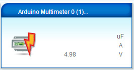
I have commented accordingly on your pull request.
-
[Solved] Support for S_MULTIMETER and V_VOLTAGE in VeraCan anyone confirm if S_MULTIMETER and V_VOLTAGE are supported in Vera?
L_Arduino.lua indicates it is supported
Whereas Selecting a Controller, indicates it is not supported
Using
MyMessage msgVolt(CHILD_ID_VOLTAGE, V_VOLTAGE);and
present(CHILD_ID_VOLTAGE, S_MULTIMETER);The Multimeter device is created
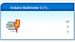
but the values are blank.The Vera log shows the 'Voltage' value is being sent with the correct value
50      06/11/17 14:25:48.875   luup_log:78: Arduino: Set variable: 1;0;1;0;38;4.79 <0x2ebbe680>
50      06/11/17 14:25:48.876   luup_log:78: Arduino: Setting variable 'Voltage' to value '4.79' <0x2ebbe680>
50      06/11/17 14:25:48.876   luup_log:78: Arduino: urn:micasaverde-com:serviceId:EnergyMetering1,Voltage, 4.79, 87 <0x2ebbe680>
Is it possible to get this to appear in the Multimeter device?
-
[Solved] Vera device not showing variable value on GUI -
[Solved] Vera device not showing variable value on GUISolved:
Vera does not have a dedicated moisture device, S_MOISTURE is implemented as a Light Sensor (Ref)
MyMessage msgMoisture(CHILD_ID_MOISTURE, V_HUM);is therefore incorrect and results in no value being shown in the device.
For Vera this has to be
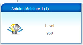
MyMessage msgMoisture(CHILD_ID_MOISTURE, V_LEVEL);The level is now showing in the device
-
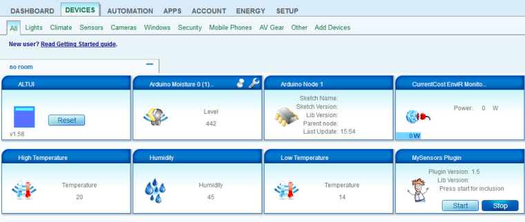
[Solved] Vera device not showing variable value on GUII have built my first sensor (moisture sensor) and gateway.
With a simple sketch the value displays correctly in the Vera device.
// Enable debug prints to serial monitor
#define MY_DEBUG

// Enable and select radio type attached
#define MY_RADIO_NRF24
#define CHILD_ID 0

#include <MySensors.h>
// Here we are setting up some water thresholds that we will
// use later. Note that you will need to change these to match
// your soil type and environment. It doesn't do much for me because I'm using domoticz
int thresholdUp = 400;
int thresholdDown = 075;
MyMessage msg(CHILD_ID, V_LEVEL);
unsigned long SLEEP_TIME = 1000;

// We are setting up the pin A0 on the redboard to be our sensor
// pin input:
int sensorPin = A0;

void presentation()
{
present(CHILD_ID, S_MOISTURE);
}

void loop()
{
int sensorValue;
sensorValue = analogRead(sensorPin);

//send back the values
send(msg.set(sensorValue));
// delay until next measurement (msec)
sleep(SLEEP_TIME);
}
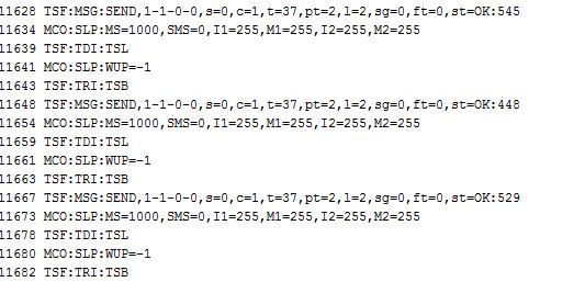
Debug output
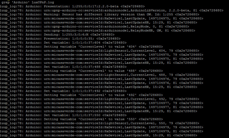
Vera grep log output
However, when I move onto the sketch I want to use everything works except the moisture value does not display in the Vera device.
/**
 * The MySensors Arduino library handles the wireless radio link and protocol
 * between your home built sensors/actuators and HA controller of choice.
 * The sensors forms a self healing radio network with optional repeaters. Each
 * repeater and gateway builds a routing tables in EEPROM which keeps track of the
 * network topology allowing messages to be routed to nodes.
 *
 * Created by Henrik Ekblad <henrik.ekblad@mysensors.org>
 * Copyright (C) 2013-2015 Sensnology AB
 * Full contributor list: https://github.com/mysensors/Arduino/graphs/contributors
 *
 * Documentation: http://www.mysensors.org
 * Support Forum: http://forum.mysensors.org
 *
 * This program is free software; you can redistribute it and/or
 * modify it under the terms of the GNU General Public License
 * version 2 as published by the Free Software Foundation.
 *
 * Code and ideas from
 * mfalkvidd (http://forum.mysensors.org/user/mfalkvidd),
 * carlierd (https://www.openhardware.io/user/97/projects/carlierd)
 * Scalz (https://www.openhardware.io/user/12/projects/scalz)
 */

/**************************************************************************************/
/* Moisture sensor Pro Mini                                                           */
/*                                                                                    */
/* Version     : V1.1.2                                                                 */
/* Supported Hardware     : V1.1.x                                                    */
/* Date        : 15/03/2017                                                           */
/* Modified by : Jordan Bouey                                                         */
/**************************************************************************************/

 /* Fuse L:E2 H:DA E:06 x
  *  BOD 1.8V - Int 8Mhz Osc
  *  avec boot  ATmegaBOOT_168_atmega328_pro_8MHz.hex
  */

#define MY_NODE_ID 1

#define MY_DEBUG    // Enables debug messages in the serial log
#define MY_DEBUG_VERBOSE_SIGNING

// Enable and select radio type attached
#define MY_RADIO_NRF24
//#define MY_OTA_FIRMWARE_FEATURE  // Enables OTA firmware updates if DualOptiBoot
// Enables software signing
#define MY_SIGNING_SOFT
// SETTINGS FOR MY_SIGNING_SOFT
#define MY_SIGNING_SOFT_RANDOMSEED_PIN 7  //!< Unconnected analog pin for random seed
// Enable node whitelisting
//#define MY_SIGNING_NODE_WHITELISTING {{.nodeId = 0,.serial = {0xEB,0x86,0x43,0x73,0x14,0xB1,0xAF,0x0E,0x17}}}
// Enable this if you want destination node to sign all messages sent to this node.
// If enabled, You need to use securityPersonalizer for more security and change the default HMAC_KEY (https://www.mysensors.org/about/signing)
//#define MY_SIGNING_REQUEST_SIGNATURES


#include <MySensors.h>
#include <SPI.h>

//Define functions
#define round(x) ((x)>=0?(long)((x)+0.5):(long)((x)-0.5))
#define N_ELEMENTS(array) (sizeof(array)/sizeof((array)[0]))

//Constants for MySensors
#define SKETCH_NAME           "Moisture Sensor Pro Mini"
#define SKETCH_VERSION        "1.1.2"


#define CHILD_ID_VOLTAGE 0 // Id of the sensor child (default 0)
#define CHILD_ID_MOISTURE 1   // Id of the sensor child (default 1)
#define BATTERY_SENSE_PIN A0  // select the input pin for the battery sense point (default A0)
#define LED_PIN_INFO 3 //INFO LED PIN (default 3)
#define LED_PIN_WARN  4//WARNING LED PIN (default 4)
#define THRESHOLD             1.1     // Only make a new reading with reverse polarity if the change is larger than 10% (default 1.1)
#define MOISTURE_THRESHOLD    1.01    // Delta needing for sending moisture to the controler (default 1.01)
#define STABILIZATION_TIME    2000    // Let the sensor stabilize before reading (default 2000)
#define BATTERY_FULL          3300    // when full AAA (default 3300)
#define BATTERY_ZERO          2340    // 2.34V limit for 328p at 8MHz (set extended fuse to 0x06 for BOD 1.8V or you'll never see 2.34V)  (default 2340)
const int SENSOR_ANALOG_PINS[] = {A1, A2}; //(default {A1, A2})
#ifndef MY_DEBUG
  #define SLEEP_TIME            3600000 // Sleep time between reads (in milliseconds) (close to 1 hour)(default 3600000)
#endif
#ifdef MY_DEBUG
 #define SLEEP_TIME            1000 // Sleep time between reads (in milliseconds) (close to 1 sec) (default 1000)
#endif


//Variables
int oldbatteryPcnt = -1;
byte direction = 0;
int oldMoistureLevel = -1;

MyMessage msgMoisture(CHILD_ID_MOISTURE, V_HUM);
MyMessage msgVolt(CHILD_ID_VOLTAGE, V_VOLTAGE);

/**************************************************************************************/
/* Presentation                                                                       */
/**************************************************************************************/
void presentation()
{
  //Get time (for presentation)
  #ifdef MY_DEBUG
    unsigned long startTime = millis();
  #endif

  blinkLedFastly(3);

  //Start MySensors and send the sketch version information to the gateway
  sendSketchInfo(SKETCH_NAME, SKETCH_VERSION);

  //Register all sensors
  present(CHILD_ID_VOLTAGE, S_MULTIMETER);
  present(CHILD_ID_MOISTURE, S_MOISTURE);


  //Setup done !
  blinkLedFastly(3);

    //Print setup debug
  #ifdef MY_DEBUG
    int duration = millis() - startTime;
    Serial.print("[Presentation duration: "); Serial.print(duration, DEC); Serial.println(" ms]");
  #endif
}
/**************************************************************************************/
/* Initialization                                                                     */
/**************************************************************************************/
void setup()
{
  //Setup LED INFO pin
  pinMode(LED_PIN_INFO, OUTPUT);
  //Setup LED WARNING pin
   pinMode(LED_PIN_WARN, OUTPUT);

  //Set moisutre sensor pins
  for (int i = 0; i < N_ELEMENTS(SENSOR_ANALOG_PINS); i++)
    {
    pinMode(SENSOR_ANALOG_PINS[i], OUTPUT);
    digitalWrite(SENSOR_ANALOG_PINS[i], LOW);
    }


}

/**************************************************************************************/
/* Main loop                                                                          */
/**************************************************************************************/
void loop()
  {
  //Get time (for a complete loop)
  #ifdef MY_DEBUG
    unsigned long startTime = millis();
  #endif

  //Get moisture level
  int moistureLevel = readMoisture();

  //Send rolling average of 2 samples to get rid of the "ripple" produced by different resistance in the internal pull-up resistors
  //See http://forum.mysensors.org/topic/2147/office-plant-monitoring/55 for more information

  //Verify if current measurement is not too far from the previous one
  if (moistureLevel > (oldMoistureLevel * THRESHOLD) || moistureLevel < (oldMoistureLevel / THRESHOLD))
    {
    //The change was large, so it was probably not caused by the difference in internal pull-ups.
    //Measure again, this time with reversed polarity.
    moistureLevel = readMoisture();
    }


  #ifdef MY_DEBUG
  Serial.print("Soil Value: ");
  Serial.println(moistureLevel);
  send(msgMoisture.set((moistureLevel), 0));
  #endif

 if (moistureLevel > (oldMoistureLevel * MOISTURE_THRESHOLD) || moistureLevel < (oldMoistureLevel / MOISTURE_THRESHOLD)) //Send moisture only if moisture changed more than MOISTURE_THRESHOLD
  {
      if (oldMoistureLevel == -1) {
       send(msgMoisture.set((moistureLevel) / 10.23, 0));
      }else{
       send(msgMoisture.set((moistureLevel + oldMoistureLevel) / 2.0 / 10.23, 0));
      }
    //Store current moisture level
    oldMoistureLevel = moistureLevel;
  }


    //Report data to the gateway
    long voltage = getVoltageBySoft();
    int batteryPcnt = round((voltage - BATTERY_ZERO) * 100.0 / (BATTERY_FULL - BATTERY_ZERO));

   if (batteryPcnt > 100) {batteryPcnt = 100;}
   if (batteryPcnt <= 0) {batteryPcnt = 0;}
   if (oldbatteryPcnt != batteryPcnt) {
      send(msgVolt.set(voltage / 1000.0, 2));
      sendBatteryLevel(batteryPcnt);
     oldbatteryPcnt = batteryPcnt;

   }

   //Print debug
  #ifdef MY_DEBUG
    Serial.print((moistureLevel + oldMoistureLevel) / 2.0 / 10.23);
    Serial.print("%");
    Serial.print("   ");
    Serial.print(batteryPcnt);
    Serial.print("%");
    int duration = millis() - startTime;
    Serial.print("   ");
    Serial.print("["); Serial.print(duration, DEC); Serial.println(" ms]");
    Serial.flush();
  #endif

 //Sleep until next measurement - smart sleep for OTA
  blinkLedFastly(1);
  smartSleep(SLEEP_TIME);
  }


/**************************************************************************************/
/* Allows to get moisture.                                                            */
/**************************************************************************************/
int readMoisture()
  {
  //Power on the sensor and read once to let the ADC capacitor start charging
  pinMode(SENSOR_ANALOG_PINS[direction], INPUT_PULLUP);
  analogRead(SENSOR_ANALOG_PINS[direction]);

  //Stabilize and read the value
  sleep(STABILIZATION_TIME);
  int moistureLevel = (1023 - analogRead(SENSOR_ANALOG_PINS[direction]));

  //Turn off the sensor to conserve battery and minimize corrosion
  pinMode(SENSOR_ANALOG_PINS[direction], OUTPUT);
  digitalWrite(SENSOR_ANALOG_PINS[direction], LOW);

  //Make direction alternate between 0 and 1 to reverse polarity which reduces corrosion
 // direction = (direction + 1) % 2;
  return moistureLevel;
  }

/**************************************************************************************/
/* Allows to fastly blink the LED.                                                    */
/**************************************************************************************/
void blinkLedFastly(byte loop)
  {
  byte delayOn = 150;
  byte delayOff = 150;
  for (int i = 0; i < loop; i++)
    {
    blinkLed(LED_PIN_INFO, delayOn);
    delay(delayOff);
    }
  }

/**************************************************************************************/
/* Allows to blink a LED.                                                             */
/**************************************************************************************/
void blinkLed(byte pinToBlink, int delayInMs)
  {
  digitalWrite(pinToBlink,HIGH);
  delay(delayInMs);
  digitalWrite(pinToBlink,LOW);
  }

/**************************************************************************************/
/* Allows to get the real Vcc (return value in mV).                                   */
/* http://provideyourown.com/2012/secret-arduino-voltmeter-measure-battery-voltage/   */
/**************************************************************************************/
long getVoltageBySoft()
  {
  ADMUX = (0<<REFS1) | (1<<REFS0) | (0<<ADLAR) | (1<<MUX3) | (1<<MUX2) | (1<<MUX1) | (0<<MUX0);
  delay(50);  // Let mux settle a little to get a more stable A/D conversion
  //Start a conversion
  ADCSRA |= _BV( ADSC );
  //Wait for it to complete
  while (bit_is_set(ADCSRA, ADSC));

  //Compute and return the value
  uint8_t low  = ADCL;                  // must read ADCL first - it then locks ADCH
  uint8_t high = ADCH;                  // unlocks both
  long result = (high << 8) | low;
  result = 1125300L / result;           // Calculate Vcc (in mV); 1125300 = 1.1*1023*1000
  return result;                        // Vcc in millivolts
  }


/**************************************************************************************/
/* Mesure battery with divider                                                        */
/*                                                                                    */
/**************************************************************************************/
long getVoltageByHard()
  {
    analogReference(INTERNAL);

   // get the battery Voltage
   int sensorValue = analogRead(BATTERY_SENSE_PIN);
   #ifdef MY_DEBUG
   Serial.print("Battery Value: ");
   Serial.println(sensorValue);
   #endif

      //The analog reference only changes when you make an analogread and it takes a little time to change, hence the tempo and repeat of the analogRead command
      delay(1000);     // this delay is needed
      sensorValue = analogRead(BATTERY_SENSE_PIN);


   #ifdef MY_DEBUG
   Serial.print("Battery Value: ");
   Serial.println(sensorValue);
   #endif

   // 1M, 470K divider across battery and using internal ADC ref of 1.1V
   // Sense point is bypassed with 0.1 uF cap to reduce noise at that point
   // ((1e6+470e3)/470e3)*1.1 = Vmax = 3.44 Volts
   // 3.44/1023 = Volts per bit = 0.003363075

    float batteryV  = sensorValue * 0.003363075;
    int batteryMv  = round(batteryV * 1000);
   // int batteryPcnt = sensorValue * 0.0977517106549365;

  int batteryPcnt = round((batteryMv - BATTERY_ZERO) * 100.0 / (BATTERY_FULL - BATTERY_ZERO));
  if (batteryPcnt > 100) {batteryPcnt = 100;}

   #ifdef MY_DEBUG

   Serial.print("Battery Voltage: ");
   Serial.print(batteryMv);
   Serial.println(" mV");

   Serial.print("Battery percent: ");
   Serial.print(batteryPcnt);
   Serial.println(" %");
   #endif

   analogReference(DEFAULT);
  return batteryMv;                        // Vcc in mV
  }
Debug output
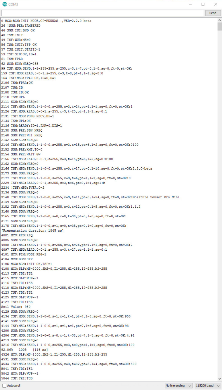
Vera grep log output
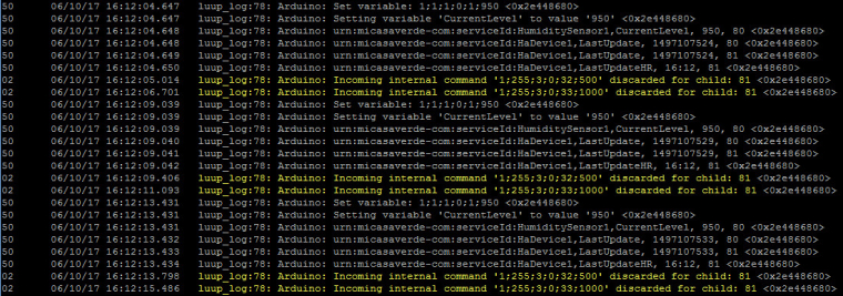
The variable value is getting to the Vera device as it shows in the device advanced tab
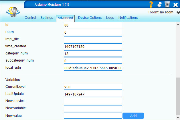
Vera 3 UI15
IDE 1.8.2
MySensor library 2.2.0 - betaI have removed the sensors and gateway multiple times, reloaded Vera multiple times. To no avail.
Any suggestions welcome.
