Skip to content

My Project

Show off and share your great projects here! We love pictures!
962 Topics 13.4k Posts
  • 2 Votes
    4 Posts
    2k Views
    Nca78N
    @user2684 I forgot to tell you to buy one with a cable. They use a connector with 1.25mm spacing and it is not possible to connect anything else. You can make the cable breadboard friendly by soldering the ends to a 2.54mm header. [image: 1546224745347-img_20181231_095020-2-resized.jpg]
  • Reporting an independent float switch and relay

    7
    0 Votes
    7 Posts
    973 Views
    S
    Success. stole some code from a post a while ago: No concept of how efficient this is, but hey... The MySensors Arduino library handles the wireless radio link and protocol between your home built sensors/actuators and HA controller of choice. The sensors forms a self healing radio network with optional repeaters. Each repeater and gateway builds a routing tables in EEPROM which keeps track of the network topology allowing messages to be routed to nodes. Created by Henrik Ekblad <henrik.ekblad@mysensors.org> Copyright (C) 2013-2018 Sensnology AB Full contributor list: https://github.com/mysensors/MySensors/graphs/contributors Documentation: http://www.mysensors.org Support Forum: http://forum.mysensors.org This program is free software; you can redistribute it and/or modify it under the terms of the GNU General Public License version 2 as published by the Free Software Foundation. ******************************* REVISION HISTORY Version 1.0 - Henrik Ekblad DESCRIPTION Example sketch showing how to control physical relays. This example will remember relay state after power failure. http://www.mysensors.org/build/relay */ // Enable debug prints to serial monitor #define MY_DEBUG 
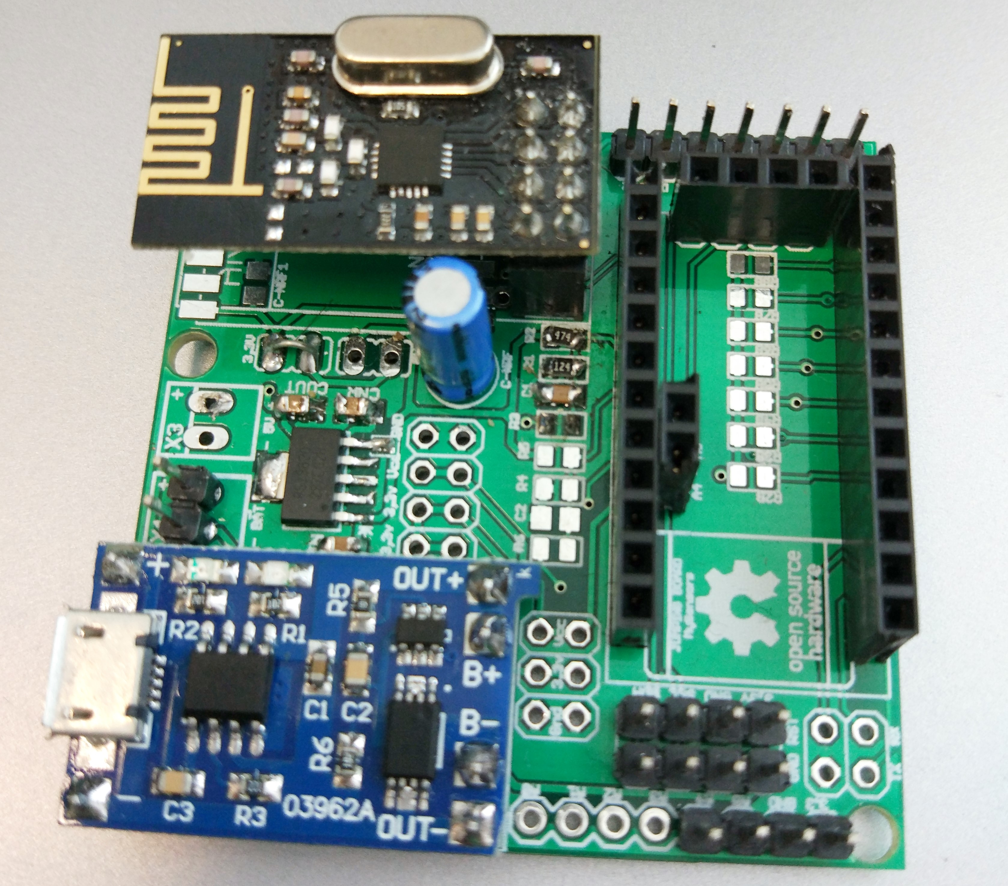
// Enable and select radio type attached #define MY_RADIO_RF24 //#define MY_RADIO_NRF5_ESB //#define MY_RADIO_RFM69 //#define MY_RADIO_RFM95 // Enable repeater functionality for this node //#define MY_REPEATER_FEATURE #include <MyConfig.h> #include <MySensors.h> #include <SPI.h> #
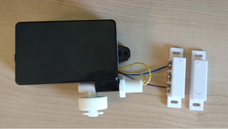
define RELAY_PIN 4 // Arduino Digital I/O pin number for first relay (second on pin+1 etc) #define FLOAT_SWITCH_PIN 3 //FLOAT SWITCH PIN #define LED_GRN_PIN 7 #define LED_RED_PIN 8 #define MY_TRANSPORT_WAIT_READY_MS (3000) #define CHILD_ID 4 #define RELAY_ON 1 #define RELAY_OFF 0 boolean lastSensorState; unsigned long lastUpdate; MyMessage msg(CHILD_ID, V_STATUS); void setup() { pinMode(RELAY_PIN, OUTPUT); pinMode(FLOAT_SWITCH_PIN, INPUT); // Define LED pinMode(LED_GRN_PIN, OUTPUT); pinMode(LED_RED_PIN, OUTPUT); } void presentation() { // Send the sketch version information to the gateway and Controller sendSketchInfo("Rollermat", "3.0"); // Register all sensors to gw (they will be created as child devices) present(CHILD_ID, S_BINARY); } void loop() { // LOW corresponds to the float switch being at its highest point (i.e. rollermat is clogged) if(digitalRead(FLOAT_SWITCH_PIN) == LOW) { digitalWrite(RELAY_PIN, RELAY_ON); //turn on the motor digitalWrite(LED_GRN_PIN, LOW); //turns on the Green LED digitalWrite(LED_RED_PIN, HIGH); //turns off the Red LED } //otherwise the float switch is HIGH // HIGH corresponds to the float switch being at its lowest point (i.e. rollermat is clean and water is flowing) else { digitalWrite(RELAY_PIN, RELAY_OFF); //turns off the pump digitalWrite(LED_GRN_PIN, HIGH); //turns off the Green LED digitalWrite(LED_RED_PIN, LOW); //turns on the Red LED } boolean sensorState = digitalRead(FLOAT_SWITCH_PIN); if (sensorState != lastSensorState) { #ifdef DEBUG digitalWrite(FLOAT_SWITCH_PIN,sensorState? HIGH : LOW); Serial.println(sensorState? "Motor On" : "Motor Off"); #endif send(msg.set(sensorState?"1":"0")); // Update gateway on change of state lastSensorState = sensorState; } }
  • 2 Votes
    1 Posts
    975 Views
    No one has replied
  • DHT11 sensor with shield LoRa rfm915

    2
    0 Votes
    2 Posts
    547 Views
    mfalkviddM
    Hi @tahsin_06, welcome to the MySensors community! Did you look at the troubleshooting guide? It shows the most common problems and how to troubleshoot them. Could you post the debug output from your gateway and node?
  • Batt/temp/hum/light/6*dig pcb for grabs

    2
    1 Votes
    2 Posts
    731 Views
    YveauxY
    @jimmy-loyens You can post your (hardware) designs on www.openhardware.io, which is the MySensors hardware site!
  • Looking for a good platform to programm webserver linked to webservices

    4
    0 Votes
    4 Posts
    820 Views
    TheoLT
    I'm currently learning react.js as my new front end language. I like it so far. Also with react native you can develop native mobile apps. That's on my bucket list for the next holiday.
  • [Need help] Intercom project

    19
    0 Votes
    19 Posts
    8k Views
    bjacobseB
    @orri Did you read the manual? if not read below... In-house telephone light button Each in-house telephone has a light button to actuate a joint staircase or entrance light. https://www.siedle.com/App/WebObjects/XSeMIPS.woa/cms/documentdownload/locale.enGB/did.7750/System_Manual_1%2Bn_technology_136442_EN.pdf
  • plant watering node

    8
    3
    2 Votes
    8 Posts
    2k Views
    alowhumA
    @dzjr Yes it is, in theory. it's a three-way valve. I haven't tested it yet though. For now my plant health monitor just monitors 6 plants. It's part of a large project about privacy in the smart home that I will be revealing in the coming year. [image: 1543823744169-plant_health_sensor.png]
  • Humidifier / Essence oil vaporize - anti dry-out monitor (WIP)

    3
    2
    1 Votes
    3 Posts
    796 Views
    alowhumA
    Wow, this is amazing! Also: congratulations!
  • How do I push Notification within Arduino IDE sketch?

    nodemcu sct-013
    2
    0 Votes
    2 Posts
    510 Views
    TheoLT
    @goddur I'm sorry my friend. I think this question is not related to MySensors. I've googled it for you. https://www.instructables.com/id/ESP8266-to-IFTTT-Using-Arduino-IDE/
  • AC Mains + Battery powered iOT-Node

    1
    1 Votes
    1 Posts
    603 Views
    No one has replied
  • Old school phone as doorbell and domoitcs interface!

    6
    1
    6 Votes
    6 Posts
    2k Views
    YveauxY
    @superkris well, at least someone did : https://hackaday.com/2018/11/20/retro-wall-phone-becomes-a-doorbell-and-so-much-more/#more-333555 Congrats!
  • Monitor Alarm System state (Jablotron)

    2
    3 Votes
    2 Posts
    3k Views
    Y
    sorry to bump this old thread. Since i have this jablotron alarm system, in this way i can also get the status of all wireless sensors (doors, etc) connected ?
  • PH Probe code

    6
    0 Votes
    6 Posts
    2k Views
    S
    I'm not a programmer, I can not fix it
  • livolo Glass Panel Touch Light Wall Switch + arduino 433Mhz

    135
    0 Votes
    135 Posts
    107k Views
    A
    Hi All, I'm trying a different approach, on how to use just the top (sensor) part of the livolo touch switch, but at the moment, i'm stuck at the PIC16f690 microcontroller functions in order to power up the LED. I'm using a Livolo VL-C601-2 model and based on the wires on the top part, i tried to make a diagram to batter understand the schematics. (Please note that i'm missing some wires and that i have not drawn all the wires from all the pins as i could not see all of them. If something is wrong, please let me know.) What i don't understand from the diagram below, is how does the PIC16F690 controls the two LEDs (red and blue) using only the RB4 (13) pin. From the datasheet link here i can see that the Pin 13 (RB4) has: RB4/AN10/SDI/SDA and supports IOC Can someone please explain to a noob in electronics how does this work and how does the pic switches from one LED to the other ? [image: 48167399-81ec4a00-e2e3-11e8-8301-d3679d37dcc4.png]
  • Door + flood sensor

    4
    2
    3 Votes
    4 Posts
    5k Views
    U
    @jhussain the board is the one pointed out by @mfalkvidd and as for the wiring it is very simple: the door sensor has one wire connected to pin 3 (since interrupt based) and the other to ground, the flood sensor has one connected to pin 6 (can be any) and the other to ground.
  • 1 Votes
    2 Posts
    605 Views
    mfalkviddM
    Hi @jhussain, welcome to the MySensors forum! The controller used is Vera https://www.mysensors.org/controller/vera You can control led lights using this example, or conventional lights using this example.
  • Temp, pressure, humidity + OLED

    5
    2
    1 Votes
    5 Posts
    3k Views
    jumpingJ
    @skysonic said in Temp, pressure, humidity + OLED: Great project what sketch have you used? i am very interested to make a temprature switch for my kitchen with that kind of display great work thank you! My sketch is based on bme280 temp, hum, pressure sketch plus the oled display. bye
  • 18650 / newbie board / boost??

    18650 battery newbie pcb
    5
    1 Votes
    5 Posts
    2k Views
    CrankyCoderC
    @alexsh1 the reason i am using the 18650's is the fact i have a steady stream of them coming in for my large battery packs. I have a couple hundred that aren't dead but just aren't quite up to to the standard i am putting in my big packs.
  • 0 Votes
    1 Posts
    474 Views
    No one has replied

10

Online

11.7k

Users

11.2k

Topics

113.1k

Posts