ok, so I figured it out... and just recording my observatios and fix in the hope it helps others or me if I forget :)
@yveaux and @zboblamont said to use the MyS sleep() function which can handle interupts on pins 2 & 3. For me this is too limitiing as I am using 4 pins.
What I needed was something simple for a rapid build. When I intially built the node a month ago I read up on the MyS sleep function, realised that it couldnt handle more than 2 pins for interupts and opted to go down the route of interupts as laid out on www.gammon.com.au. After a little more reading I then implemented the AVR sleep function, so far so good or so I thought - move fwd to my problem. While everything was working well:
scene controller HW built - check,
Software created - check,
Enclosure printed - check,
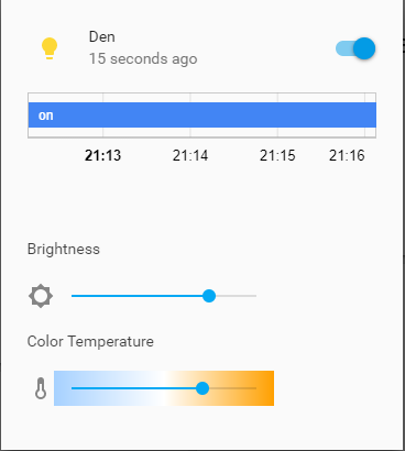
hooked up to home assitant - check,
WAF (very important) - check,
...the node wasnt actaully sleeping DOH!
Upto this point I had spent less than 6 hours in dev and implementation time....
So heres the problem, after a lot of reading over the last 36 hours I found a post that states MyS library only implements interupts for pins 2&3 on the pro mini - it doesnt implement interupt groups such as PCINT1 (A0-A5) etc AND the node cannot be woken up via interupt if it is not done via pins 2&3.
@electrik posted a link to his excellent sketch that hacks the core code a little - as I was looking into this method I stumbled on a post by @freynder that implements a 'dirty hack' here which forces the node to wake up on interupt when using the MyS sleep() function. This then led me to a post on a 6/8 button controller here. These two posts have be pivotal in fixing my problem. Thank you @electrik for triggering the thought process that lead to a simple solution :)
@yveaux and @zboblamont you where both correct I need to use the MyS sleep() function which I have now implemented alongside the external interupt library form the 6/8 button controller link and the added the two lines of code as per the 'dirty hack'
My node now reads 18mA when active (transmitting) and when sleeping it is less than 0.5mA - which is the limitation of my equipment!
@zboblamont to answer your Q about node setup, I have a pro mini and with both the power led and regulator removed as per the MySensors hack for battery nodes - however the transmit led is still connected which will draw extra current when transmitting, which I am ok with for the moment lol
thank you to all that have contributed !!
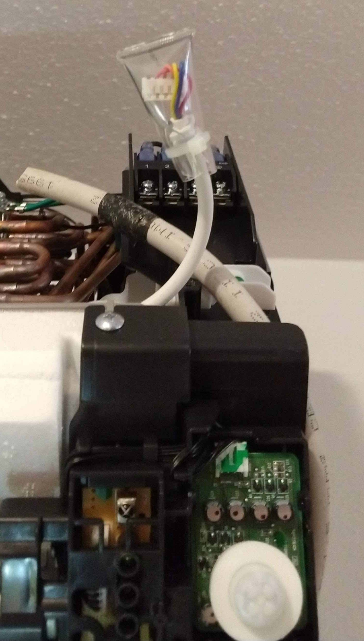
heres the schematic of the controller:
[image: 1562240086946-scene-controller-resized.jpg]
and an updated extract of the code
#define MY_DEBUG true // Enable debug prints
#define MY_RADIO_NRF24 // Enable and select radio type attached
#define MY_NODE_ID 7 // >>>>>>>>Set the node ID manually - this must be set the mysensors.h call<<<<<<<<<<<<<<<<<<<<<<<<<<<<<<<<
#include <MySensors.h>
#include <OneButton.h> // https://github.com/mathertel/OneButton
#define EI_NOTEXTERNAL // External interrupts managed by built-in routines
#include <EnableInterrupt.h> // Pin-change interrupts
#define MIN_V 1.9 // Minimum Battery Voltage
#define MAX_V 3.1 // Max Battery Voltage
#define CHILD_ID_BUTTON1 1
#define CHILD_ID_BUTTON2 2
#define CHILD_ID_BUTTON3 3
#define CHILD_ID_BUTTON4 4
#define CHILD_ID_BATTERY 5
#define CHILD_ID_ADC 6
#define SN "Scene Controller"
#define SV "0.4"
#define BUTTON4 A1 // Interput pin and button definitions
#define BUTTON1 A2
#define BUTTON3 A0
#define BUTTON2 A3
OneButton button4(BUTTON4, true); // Setup a new OneButton on pin A1.
OneButton button1(BUTTON1, true); // Setup a new OneButton on pin A2.
OneButton button3(BUTTON3, true); // Setup a new OneButton on pin A0.
OneButton button2(BUTTON2, true); // Setup a new OneButton on pin A3.
int SendDelay = 500; // Time to wait before sending data over the radio
int BATTERY_SENSE_PIN = A5; // Define battery sense pins
int oldBatteryPcnt = 0;
//int batteryCounter = BATTERY_REPORT_CYCLE -1; // counter for battery update
//int reportCounter = FORCE_TRANSMIT_CYCLE -1; // counter for the loop and forcing updates
unsigned long StartTime = 0; // sleep startime variable
unsigned long SleepWaitTime = 10000; // Time to wait before going to sleep 10 seconds
unsigned long Sleep_Time = 86400000; // 86400000 Sleep for 24 hours
int MessageA = 0; // Button Message Values 0- no value
int MessageB = 1; // up
int MessageC = 2; // down
int MessageD = 3; // toggle on/off
MyMessage msgButton1(CHILD_ID_BUTTON1, V_SCENE_ON);
MyMessage msgButton2(CHILD_ID_BUTTON2, V_SCENE_ON);
MyMessage msgButton3(CHILD_ID_BUTTON3, V_SCENE_ON);
MyMessage msgButton4(CHILD_ID_BUTTON4, V_SCENE_ON);
MyMessage msgBattery(CHILD_ID_BATTERY, V_VOLTAGE);
MyMessage msgADCValue(CHILD_ID_ADC, V_VOLTAGE);
/*
####################################################
# #
# Presentaion #
# #
####################################################
*/
void presentation()
{
sendSketchInfo(SN, SV); wait(SendDelay); // Send the sketch version information to the gateway
present(CHILD_ID_BUTTON1, S_SCENE_CONTROLLER); wait(SendDelay); // Register all sensors to gw (they will be created as child devices)
present(CHILD_ID_BUTTON2, S_SCENE_CONTROLLER); wait(SendDelay);
present(CHILD_ID_BUTTON3, S_SCENE_CONTROLLER); wait(SendDelay);
present(CHILD_ID_BUTTON4, S_SCENE_CONTROLLER); wait(SendDelay);
present(CHILD_ID_BATTERY, S_MULTIMETER); wait(SendDelay);
present(CHILD_ID_ADC, S_MULTIMETER); wait(SendDelay);
// metric = getControllerConfig().isMetric;
}
/*
####################################################
# #
# Void Setup #
# #
####################################################
*/
void setup()
{
analogReference(INTERNAL);
Serial.begin(115200); // Setup the Serial port. see http://arduino.cc/en/Serial/IfSerial
Serial.println("Starting..."); delay(10);
button1.attachClick(click1); // Button 1 functions.
button1.attachDoubleClick(doubleclick1);
button1.attachLongPressStop(longPressStop1);
button2.attachClick(click2); // Button 2 functions.
button2.attachDoubleClick(doubleclick2);
button2.attachLongPressStop(longPressStop2);
button3.attachClick(click3); // Button 3 functions.
button3.attachDoubleClick(doubleclick3);
button3.attachLongPressStop(longPressStop3);
button4.attachClick(click4); // Button 4 functions.
button4.attachDoubleClick(doubleclick4);
button4.attachLongPressStop(longPressStop4);
enableInterrupt(BUTTON1,Int_vect,CHANGE);
enableInterrupt(BUTTON2,Int_vect,CHANGE);
enableInterrupt(BUTTON3,Int_vect,CHANGE);
enableInterrupt(BUTTON4,Int_vect,CHANGE);
}
/*
####################################################
# #
# Void Loop #
# #
####################################################
*/
void loop()
{
if((millis() - StartTime) >= SleepWaitTime) // Wait for some time before going to sleep
{
Serial.println("Sleeping....");
delay(10);
sleep(Sleep_Time); // Sleepy Time :)
// WAKE UP HERE
_wokeUpByInterrupt = INVALID_INTERRUPT_NUM; //dirty hack wake up routine - clear interupt
StartTime = millis();
Serial.println("Awake...");
int battery_read; // call function - Send the battery status
battery_read = SendBattery();
}
button1.tick(); // Check the push buttons:
button2.tick();
button3.tick();
button4.tick();
delay(10);
}
/*
####################################################
# #
# Interupt Service Routine #
# #
####################################################
*/
void Int_vect() // handle pin change interrupt for A0 to A5 here
{
//Serial.println("--**-INTERRUPT-**--"); //debug
_wokeUpByInterrupt = 0xFE; // Dirty hack to get out of MySensors sleep loop
}