Skip to content

Troubleshooting

Help! Everything just falls apart
2.7k Topics 21.5k Posts
  • Standalone atmega328p and nrf24 not working.

    11
    0 Votes
    11 Posts
    3k Views
    S
    Awrgh! Sorry! Its working! There was small white jumper from previous project connected from VCC to CSN. Thank you for help. [image: 1502792681857-20170815_121950-resized.jpeg]
  • Adding 4th dimmer. Struggle.

    9
    0 Votes
    9 Posts
    3k Views
    BulldogLowellB
    I can't test this but something like: #define SN "Four Fader Test" #define SV "0.1a" #define NUMBER_OF_DIMMERS 4 //System settings #define MY_RADIO_NRF24 #define MY_RF24_CE_PIN 8 //ADDED #define MY_NODE_ID 71 #include <MySensors.h> #include <SPI.h> #include "Fade.h" MyMessage dimmer[NUMBER_OF_DIMMERS]; MyMessage light[NUMBER_OF_DIMMERS]; Fade fader[NUMBER_OF_DIMMERS]; byte leds[NUMBER_OF_DIMMERS] = {3, 5, 6, 9}; void before() { int i = 0; for (auto fdr : fader) { fdr = Fade(leds[i++], 10, 0, 255, MILLIS_TIMER); // led speed 5 milliseconds/step; pwm at 0 min and 255 max (MILLIS_TIMER) fdr.begin(); } i = 0; for (auto msg : dimmer) msg = MyMessage(i++, S_DIMMER); i = 0; for (auto msg : light) msg = MyMessage(i++, S_BINARY); } void presentation() { sendSketchInfo(SN, SV); int i = 0; for (auto d : dimmer) present(i++, S_DIMMER); } void setup() { Serial.begin(9600); Serial.println(F("Setup Complete...")); } void loop() { uint32_t currentMillis = millis(); for (auto fdr : fader) fdr.update(currentMillis); } void receive(const MyMessage &message) { if (message.type == V_STATUS || message.type == V_PERCENTAGE) { int requestedLevel = atoi(message.data); if (message.type == V_STATUS) requestedLevel = requestedLevel ? 100 : 0; else requestedLevel = constrain(requestedLevel, 0, 100); fader[message.sensor].setTarget(map(requestedLevel, 0, 100, 0, 255)); send(light[message.sensor].set(requestedLevel > 0 ? 1 : 0)); send(dimmer[message.sensor].set(requestedLevel)); } } I used my non-blocking Fade.h: #ifndef Fade_h #define Fade_h #include <Arduino.h> enum timer{ MILLIS_TIMER, MICROS_TIMER }; class Fade { public: Fade() {}; Fade(int pin, uint32_t timeStep = 15, uint8_t minVal = 0, uint8_t maxVal = 255, timer timerSelect = MILLIS_TIMER); void begin(); void setTarget(int to); void update(); void update(uint32_t time); uint8_t getMin(); uint8_t getMax(); uint8_t getCurrent(); uint32_t readSpeed(); uint32_t writeSpeed(uint32_t time); uint8_t getSetpoint(); private: uint8_t _min; uint8_t _max; uint8_t _targetFade; uint8_t _pwmRate; uint32_t _time; uint32_t _last; uint8_t _pin; bool _microsTimer; }; #endif and my Fade.cpp: #include "Fade.h" #include <Arduino.h> Fade::Fade(int pin, uint32_t timeStep, uint8_t minVal, uint8_t maxVal, timer timerSelect) { _pin = pin; _time = timeStep; _min = minVal; _max = maxVal; analogWrite(_pin, _min); _pwmRate = _min; _microsTimer = timerSelect; } void Fade::begin() { analogWrite(_pin, _min); } void Fade::setTarget(int to) { _targetFade = (uint8_t) constrain(to, _min, _max); this->update(); } void Fade::update() { this->update(_microsTimer? micros() : millis()); } void Fade::update(uint32_t time) { if (time - _time > _last) { _last = time; if (_pwmRate > _targetFade) analogWrite(_pin, --_pwmRate); if (_pwmRate < _targetFade) analogWrite(_pin, ++_pwmRate); } } uint8_t Fade::getSetpoint() { return _targetFade; } uint8_t Fade::getCurrent() { return _pwmRate; } uint32_t Fade::readSpeed() { return _time; } uint32_t Fade::writeSpeed(uint32_t time) { _time = time; } uint8_t Fade::getMin() { return _min; } uint8_t Fade::getMax() { return _max; }
  • Sensor connected to Gateway but sending no data

    5
    0 Votes
    5 Posts
    2k Views
    X
    Hello there, so i made a huge step forward i think! :) Raspberri Pi with the current version of openhabian and mqtt is up and running. Mysensors Ethernet MQTT Gateway is also working Just flashed the DHT11 example on my Arduino Pro mini. What is the next step to show the temperature and humidity in openHAB? The manual is just confusing ;( EDIT 13.08.2017 16:20 IP of my Arduino MQTT Gatewas is 192.168.178.28 IP Openhabian Raspberry3 is 192.168.178.27 Thus is used "sudo nano /etc/openhab2/services/mqtt.cfg" to change "broker.url=tcp://192.168.178.27:1883" Or is my arduino the Broker? :( EDIT 13.08.2017 22:12 OK MQTT was succesfully linked on my Raspberry I can toggle a switch item in openHAB sending MQTT Commands from my PC using MQTTFX Next Step would be Linking MQTT Packages from mysensors MQTT Gateway to openHAB Items EDIT 14.08.2017 21:30 HORAY! OpenHAB is showing temperature and humidity! SO HAPPY :) Thank you! LOG of my Mysersors MQTT Ethernet Gateway: 0;255;3;0;9;MCO:BGN:INIT GW,CP=RNNGA--,VER=2.1.1 0;255;3;0;9;TSM:INIT 0;255;3;0;9;TSF:WUR:MS=0 0;255;3;0;9;TSM:INIT:TSP OK 0;255;3;0;9;TSM:INIT:GW MODE 0;255;3;0;9;TSM:READY:ID=0,PAR=0,DIS=0 0;255;3;0;9;MCO:REG:NOT NEEDED IP: 192.168.178.28 0;255;3;0;9;MCO:BGN:STP 0;255;3;0;9;MCO:BGN:INIT OK,TSP=1 IP: 192.168.178.28 0;2/18 ;0;9;Attempting MQTT connection... 0;255;3;0;9;MQTT connected 0;255;3;0;9;Sending message on topic: mygateway1-out/0/255/0/0/18 0;255F:PNG:SEND,TO=0 0;255;3;0;9;TSF:CKU:OK 0;255;3,l=0,sg=0: 0;255;3K ;9;TSF:MSG:BC 0;255;3;0;9;TSF:MSG:FPAR REQ,ID=2 0;255;3;0;9;TSF:PNG:SEND,TO=0 0;255;3;0;9;TSF:CKU:OK 0;255;3;0;9;TSF:MSG:GWL OK 0;255;3;0;9;TSF:MSG:SEND,0-0-2-2,s=255,c=3,t=8,pt=1,l=1,sg=0,ft=0,st=OK:0 0;255;3;0;9;TSF:MSG:READ,2-2-0,s=2t=0,st=OK:1 pt=1,l=1,sg=0:1 0;255;3;0;9;TSF:MSG:PINGED,ID=2,HP=1 0,sg=0:0100 0;255;3;0;9;TSF:MSG:SEND,0-0-2-2,s=255,c,l=1,sg=0,ft=l=2,sg=0,ft=0,st=OK:0100 0;255;3;0;9;TSF:MSG:READ,2-2-0,s=255,c=0,t=17,pt=0,l=5,sg=0:2.1.1 0;255;3;0;9;Sening message on topic: mygateway1-out/2/255/0/0/17 0;255;3;0;9;TSF:MSG:READ,2-2-0,s=255,c=3,t=6,pt=1,l=1,sg=0:0 0;255;3;0;9;Sending message on topic: mygateway1-out/2/255/3/0/6 7 0;255;3;0;9;TSF:MSG:READ,2-2-0,s=255,c=3,t=6,pt=1,l=1,sg=0:0 0;255;3;0;9;Sending message on topic: mygateway1-out/2/255/3/0/6 0;255;3;0;9;TSF:MSG:READ,2-2-0,s=255,c=3,t=11,pt=0,l=22,sg=0:TemperatureAndHumidity 0;25555;3;0;9;Sending message onopic: mygateway1-out/2/255/3/0/11 0;2;255;3;0;9;TSF:MSG:READ,2-2-0,s=0,c=0,t=7,pt=0,l=0,sg=0: 0;255;3;0;9g message on tge on topic: mygateway1-out/2/0/0/0/7 0;255;3;0;9;:READ,2-2-0,s=255,c=3,t=26,pt=1,l=0,l=0,:2 0;255;3;0;9;TSF:MSG:SEND,0-0-2-2,s=255,c=3,t=27,pt=1,l=1,sg=0,ft=0,st=OK:1 ;9;TSF:MSG:READ,2-2-0,s=255,c=3,t=26,pt=1,l=1,sg=0:2 0;255;3;0;9;TSF:MSG:SEND,0-0-2-2,s=255,c=3,t=27,pt=1,l=1,sg=0,ft=0,st=OK:1 ;9;TSF:MSG:READ,2-2-0,s=255,c=3,t=26,pt=1,l=1,sg=0:2 0;255;3;0;9;TSF:MSG:SEND,0-0-2-2,s=255,c=3,t=27,pt=1,l=1,sg=0,ft=0,st=OK:1 0;255;3;0;9;TSF:MSG:READ,20,s=0,c=1,t=1,pt=7,l=5,sg=0g=0:26.0 0;255;3;0;9;Sending message topic: mygateway1-out/2/0/1/0/1 /0 0;255;3;0;9;TSF:MSG:READ,2-2-0,s=0,c=1,t=1,pt=7,l=5,sg=0:63.0 0;255;3;0;9;Sending message on topic: mygateway1-out/2/0/1/0/1 Mosquiti shows following on the raspberry: [16:19:05] openhabian@openHABianPi:~$ mosquitto_sub -v -t 'mygateway1-out/#' mygateway1-out/2/0/1/0/1 60.0 mygateway1-out/2/1/1/0/0 24.0 mygateway1-out/2/0/1/0/1 62.0 mygateway1-out/2/1/1/0/0 25.0
  • openhabian +mysensors binding 2.2

    3
    0 Votes
    3 Posts
    1k Views
    ?
    so i was not crazy.... after deleting all 143 items, installing new openhab. configure everything..... yep ...i forgot to read them ... mea culpa.... ;)
  • Problem to program pro mini

    11
    0 Votes
    11 Posts
    3k Views
    sundberg84S
    @MagnusF - if the error is a bad bootloader, but that is rarely the case... I have seen that once. It will not hurt though to re-upload the bootloader if you suspect thats the problem.
  • Bootloader Error...

    1
    0 Votes
    1 Posts
    662 Views
    No one has replied
  • Two Gateway MQTT

    1
    0 Votes
    1 Posts
    477 Views
    No one has replied
  • Gas Meter

    1
    2
    0 Votes
    1 Posts
    1k Views
    No one has replied
  • Gateway stops working

    7
    0 Votes
    7 Posts
    2k Views
    M
    the BOD setting were 1.8V . I have changed them to 2.7V. Now the battery node stops when the voltage is too low, but the GW keeps running. Thank you very much
  • Reapeter and relay actuactor

    7
    0 Votes
    7 Posts
    1k Views
    G
    @rejoe2 Thanks rojoe2, I don't really use relay, too much power consumption, i use opto-triac to manage light. Less consumption and noise Will try with a single repeater, but you're right with the D18B20, it take much time each loop, i'll see the change when power on the light, there is no delay now :+1:
  • 0 Votes
    1 Posts
    788 Views
    No one has replied
  • [RESOLVED] Problems connecting node to gateway

    9
    0 Votes
    9 Posts
    2k Views
    mfalkviddM
    @firstof9 great work! Thanks for reporting back on your solution.
  • Logging debug messages over long periods

    2
    2 Votes
    2 Posts
    954 Views
    stevebusS
    Good tip! thanks for sharing
  • 0 Votes
    7 Posts
    2k Views
    mfalkviddM
    @billgoolsby the gateway could probably be called event-driven but that's not why there is no need for additional code. The concepts are described in the getting started guide, which starts at https://www.mysensors.org/about
  • Prevent Relay from triggering on power loss or broker reboot

    22
    0 Votes
    22 Posts
    8k Views
    B
    @rhuehn I know this is an old post but I had a similar issue which I solved by inserting a line in my sketch to pull the pin high before setting it as output digitalWrite(RELAY_1_PIN , HIGH); //stops relays cycling state during boot digitalWrite(RELAY_2_PIN , HIGH); //stops relays cycling state during boot pinMode(RELAY_1_PIN , OUTPUT); pinMode(RELAY_2_PIN , OUTPUT);
  • SecurityPersonalizer.ino: randomized key not shown after first step

    2
    0 Votes
    2 Posts
    540 Views
    AnticimexA
    @nog76 you are probably right. Thanks for reporting. A new release is soon to come which will change things quite a lot and documentation will update with that update.
  • NRF24 i cant configure raspberry pi1

    25
    0 Votes
    25 Posts
    4k Views
    H
    hi, I just did this setup last week and also had similar problems. I did run make without any options added. NRF24 is allready enabled by default. One thing I did was to enable SPI and then I think it worked better. There's options in "sudo raspi-config" (advanced menu) to enable I2C and SPI, could that be the issue? //Henrik
  • Compilation Error for Arduino Pro or Pro Mini

    29
    0 Votes
    29 Posts
    6k Views
    Daniel RuizD
    @rejoe2 said in Compilation Error for Arduino Pro or Pro Mini: @Daniel-Ruiz According to my experience, it normally is not necessary to change sketches. Especially not as long as they are "official" MySensors Sketches. But as soon as additional libs are concerned (here: dallasTemperature), the developers may not be able to survey all external changes that may happen. (The conversionTime calculation had been "public" in the past; this had been changed for whatever reason by the dallas-lib-guys). So this sketch originally had worked. It also may have worked, if you installed an older version of the relevant lib (with the lib manager in the IDE). Nevertheless: You most likely already got a first idea how these things work. Me too, I had to fullfill a fast learning curve... BUT: It is fun! I fully agree with you. I have already assimilated some notions thanks to your experience. I'm going to hang on and move on. I love learning and discovering new technologies. I wish you a good evening. Daniel
  • domoticz Error sending switch command](check device/hardware !)

    10
    0 Votes
    10 Posts
    4k Views
    dbemowskD
    @pjr OK, I didn't realize about the error message. I just assumed it had to do with the V-VARx problem.
  • RFM69HW Raspberry Pi 2 Gateway

    raspberry pi 2 gateway rfm69hw development
    3
    1
    0 Votes
    3 Posts
    2k Views
    NickB149N
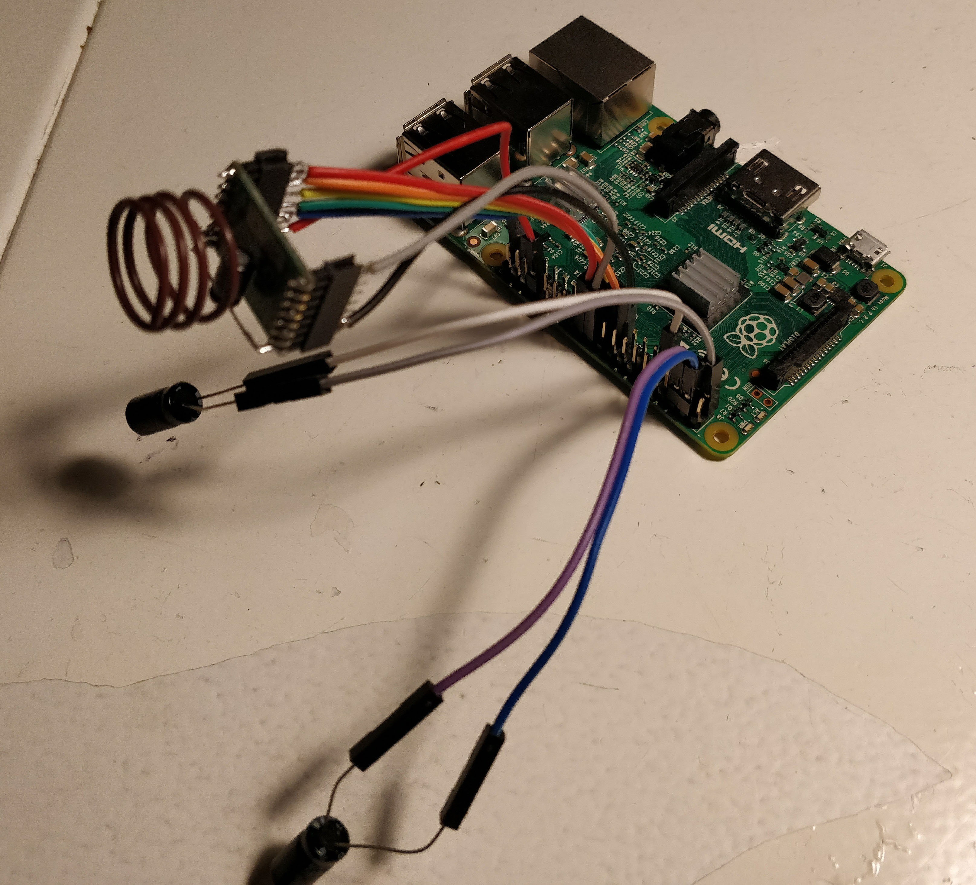
    Thanks for your quick reply! The solution was indeed to put the ./configure parameters on the same line; I also changed to a serial gateway which is now correctly recognized in Domoticz. I did not need to change any pin definitions (yet). Yeah, the two capacitors clearly shown are indeed not very effective for the radio module, there is however another capacitor directly soldered to the radio, which is a bit hidden in the picture. Thanks again for your help!

16

Online

11.7k

Users

11.2k

Topics

113.1k

Posts