Skip to content

General Discussion

A place to talk about whateeeever you want
1.5k Topics 14.2k Posts
  • RFM69 custom frequency

    5
    0 Votes
    5 Posts
    976 Views
    mfalkviddM
    @grubstake yes it is still current info and works both for the new driver and for the old driver, which is used by default (and what OP asked about) If you are using the new driver you can set the frequency in hertz if you want to.
  • Measure a node's NRF signal or distance value

    6
    0 Votes
    6 Posts
    2k Views
    F
    Thanks. I was thinking about the level that you define in beginning of sketch. RF24_PA_LEVEL
  • Sensebender gateway local sensor

    4
    0 Votes
    4 Posts
    937 Views
    mfalkviddM
    @flopp yes.
  • Combined electricity, gas and water use sensor

    11
    0 Votes
    11 Posts
    2k Views
    alowhumA
    @benhub that's an interesting thought. Wouldn't it be easier to just make the code in the main node flexible instead?
  • Node ESP8266 with NFR24 and WiFi disabled

    6
    0 Votes
    6 Posts
    958 Views
    mfalkviddM
    @apl2017 on the öast message, the node is not getting ack from the next node. The mose common cause is i sufficiently clean power supply. What size of capacitor are you using? How is the radio getting its power? Adding wait(200) before the send call can help the power to stabilize. Since all communication before works, wiring and everything else should be ok.
  • Change pin #s that the RF24 radio uses by default. Mysensors 2.0

    2
    0 Votes
    2 Posts
    536 Views
    mfalkviddM
    @tymal77 yes. See the w5100 code example at https://www.mysensors.org/build/ethernet_gateway#wiznet-w5100-ethernet-module for which #define to set.
  • 0 Votes
    2 Posts
    647 Views
    mfalkviddM
    @rjgmba hi and welcome to the forum! https://www.mysensors.org/build/connect_radio decribes how to connect the radio for any node or gateway - it is not limited to serial. A gateway has 1 transport and 1 controller interface. The transport can be rfm69, nrf24, rs485, etc The controller interface can be serial, ethernet(tcp), mqtt So what you want is probably a gateway with rfm69 transport and mqtt controller interface. Program the gateway based on the instructions on the first link you posted. Change the code from // Enables and select radio type (if attached) #define MY_RADIO_RF24 //#define MY_RADIO_RFM69 //#define MY_RADIO_RFM95 to // Enables and select radio type (if attached) //#define MY_RADIO_RF24 #define MY_RADIO_RFM69 //#define MY_RADIO_RFM95 connect the radio based on the instructions on the second link.
  • How to purchase mysensors SW protocol stack, instead of donation

    8
    1 Votes
    8 Posts
    2k Views
    alowhumA
    @flopp I'd love to hear more about the kit you want to sell. I'm working on something similar, in a way.
  • MY_RAM_ROUTING_TABLE_FEATURE - implementation questions.

    2
    2 Votes
    2 Posts
    1k Views
    alowhumA
    Does anyone have the answers to this question?
  • CSMA / LBT for RFM69 new driver

    7
    1
    0 Votes
    7 Posts
    1k Views
    mfalkviddM
    @jerby thanks for reporting. Could you share the CSMA levels for your area? (#define MY_DEBUG_VERBOSE_RFM69 and check the debug log to see what it prints)
  • Overload MySensor promini

    2
    0 Votes
    2 Posts
    498 Views
    AnticimexA
    @jerby you get the memory usage when you link your sketch.
  • CDEBYTE's new NRF24 modules are great! (and cheap)

    36
    3 Votes
    36 Posts
    9k Views
    alowhumA
    @gohan Exactly, and the project I'm working on is "no soldering and no programming required (unless you want to)". I guess I'll try ordering one of these modules and see if it can handle full power.
  • Thanks to all

    5
    0 Votes
    5 Posts
    1k Views
    fernando alvarez buyllaF
    Guys you are right is too early to quit , i have to try the RFM69 433Mhz as well before quitting , i was planning to wire my house with a 5v power supply to power all the sensors but i guess using a lower freq can help me to avoid that , will give it a try , lest just hope the rfm69 arrive, cuz i always have problems with evay , thanks guys you open mi mind one more time
  • WAF in jeopardy today

    18
    0 Votes
    18 Posts
    3k Views
    dbemowskD
    @kimot The main thing is that I got them flashed. I still have yet to figure out the new firmware and test them, but I am confident I can get them to work. Thanks again.
  • Determine if pin interupt or awakens from sleep

    9
    0 Votes
    9 Posts
    1k Views
    mfalkviddM
    @blom yes, if you hack the library or use tekka's experimental version at https://github.com/tekka007/MySensors/tree/SleepTimeLeft
  • Hardware for the ultimate smart home controller

    15
    0 Votes
    15 Posts
    3k Views
    gohanG
    I think it is more of a BT gateway to connect some of their BT devices
  • 0 Votes
    5 Posts
    2k Views
    kotzerK
    @jkandasa Any news here? (still have my rfm69 Boards here to check of the range is much better)
  • 0 Votes
    3 Posts
    629 Views
    J
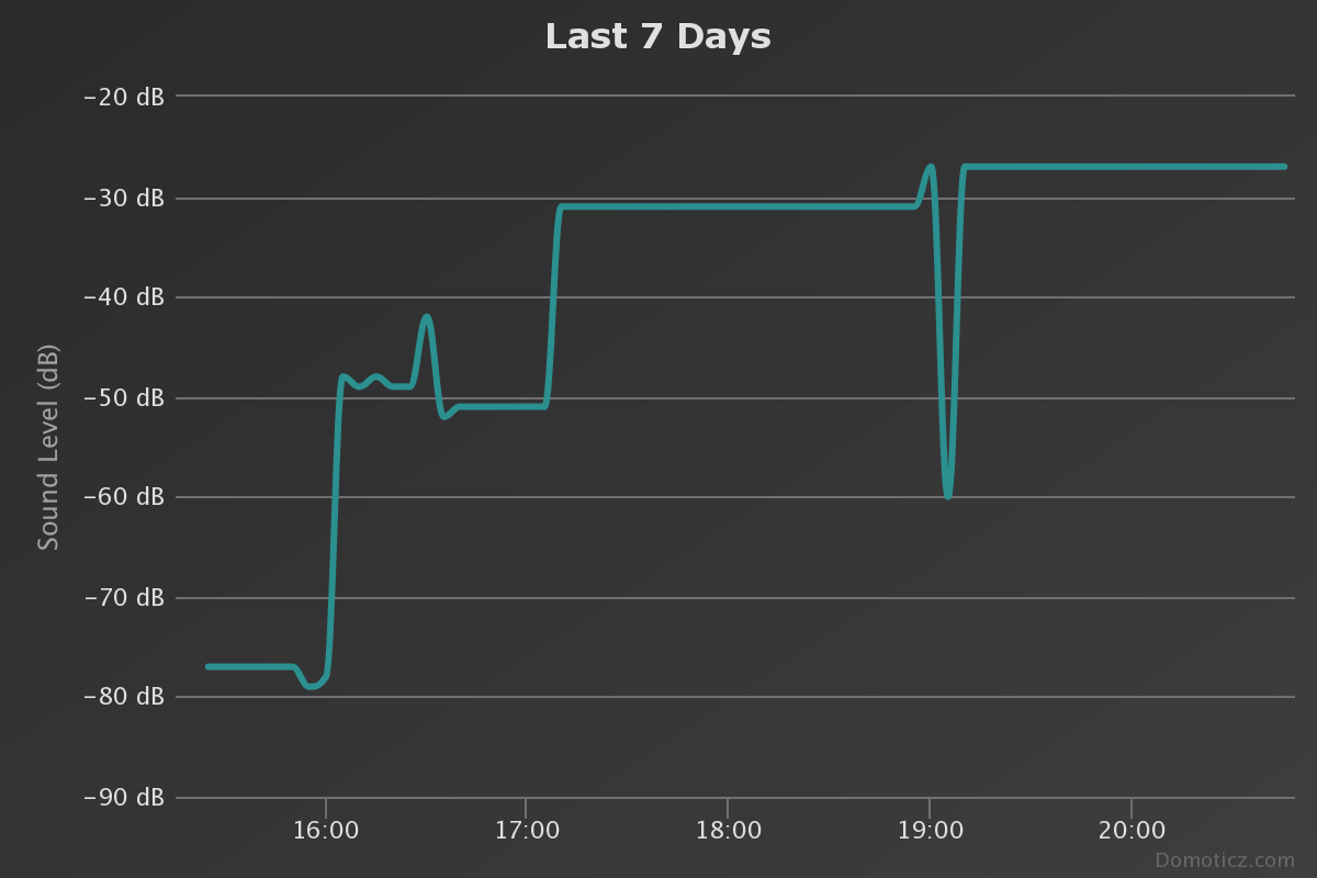
    Ahhhh, thanks @alowhum , what you said makes so much more sense. I also see some people have attempted to stream audio with Domoticz. Ok now I have a better sense of direction on what to research next. Thank you
  • Is kickstarter feature need for the openhardware?

    4
    3 Votes
    4 Posts
    948 Views
    kalinaK
    Hi @hek, I understand what is the problem now. Really, just desire is not enough))
  • ISR Pulse Meter Question

    12
    0 Votes
    12 Posts
    1k Views
    B
    Hello Here is my last code for my gas meter. If it could help somebody /* * The MySensors Arduino library handles the wireless radio link and protocol * between your home built sensors/actuators and HA controller of choice. * The sensors forms a self healing radio network with optional repeaters. Each * repeater and gateway builds a routing tables in EEPROM which keeps track of the * network topology allowing messages to be routed to nodes. * * Created by Henrik Ekblad <henrik.ekblad@mysensors.org> * Copyright (C) 2013-2018 Sensnology AB * Full contributor list: https://github.com/mysensors/MySensors/graphs/contributors * * Documentation: http://www.mysensors.org * Support Forum: http://forum.mysensors.org * * This program is free software; you can redistribute it and/or * modify it under the terms of the GNU General Public License * version 2 as published by the Free Software Foundation. * ******************************* * * REVISION HISTORY * Version 1.0 - Henrik Ekblad * Version 1.1 - GizMoCuz * * DESCRIPTION * Use this sensor to measure volume and flow of your house water meter. * You need to set the correct pulsefactor of your meter (pulses per m3). * The sensor starts by fetching current volume reading from gateway (VAR 1). * Reports both volume and flow back to gateway. * * Unfortunately millis() won't increment when the Arduino is in * sleepmode. So we cannot make this sensor sleep if we also want * to calculate/report flow. * http://www.mysensors.org/build/pulse_water */ // Enable debug prints to serial monitor #define MY_DEBUG // Enable and select radio type attached #define MY_RADIO_RF24 #include <MySensors.h> #define DIGITAL_INPUT_SENSOR 3 // The digital input you attached your sensor. (Only 2 and 3 generates interrupt!) #define CHILD_ID 1 // Id of the sensor child unsigned long loopNumber = 0; unsigned long lastLoopSend = 0; MyMessage volumeMsg(CHILD_ID, V_VOLUME); MyMessage lastCounterMsg(CHILD_ID, V_VAR1); volatile uint32_t pulseCount = 0; bool pcReceived = false; double volume = 0; //========================= // BATTERY MEASURER // VOLTAGE DIVIDER SETUP // 1M, 470K divider across battery and using internal ADC ref of 1.1V // Sense point is bypassed with 0.1 uF cap to reduce noise at that point // ((1e6+470e3)/470e3)*1.1 = Vmax = 3.44 Volts // 3.44/1023 = Volts per bit = 0.003363075 #define VBAT_PER_BITS 0.003363075 #define VMIN 2.2 // Vmin (radio Min Volt)=1.9V (564v) #define VMAX 3.2 // Vmax = (2xAA bat)=3.0V (892v) int batteryPcnt = 0; // Calc value for battery % int batLoop = 0; // Loop to help calc average int batArray[4]; // Array to store value for average calc. int BATTERY_SENSE_PIN = A0; // select the input pin for the battery sense point //========================= void setup() { // initialize our digital pins internal pullup resistor so one pulse switches from high to low (less distortion) pinMode(DIGITAL_INPUT_SENSOR, INPUT_PULLUP); pulseCount = 0; // Fetch last known pulse count value from gw request(CHILD_ID, V_VAR1); //Battery analogReference(INTERNAL); Serial.print("With Battery VMax (100%) = "); Serial.print(VMAX); Serial.print("volts and Vmin (0%) = "); Serial.print(VMIN); Serial.println(" volts"); Serial.print("Battery Percent 25%/50%/75% calculates to: "); Serial.print(((VMAX - VMIN) / 4) + VMIN); Serial.print("/"); Serial.print(((VMAX - VMIN) / 2) + VMIN); Serial.print("/"); Serial.println(VMAX - ((VMAX - VMIN) / 4)); delay(1000); int sensorValue = analogRead(BATTERY_SENSE_PIN); delay(50); float Vbat = sensorValue * VBAT_PER_BITS; int batteryPcnt = static_cast<int>(((Vbat - VMIN) / (VMAX - VMIN)) * 100.); Serial.print("Current battery are measured to (please confirm!): "); Serial.print(batteryPcnt); Serial.print(" % - Or "); Serial.print(Vbat); Serial.println(" Volts"); } void presentation() { // Send the sketch version information to the gateway and Controller sendSketchInfo("Gas Meter", "2.0"); // Register this device as Water flow sensor present(CHILD_ID, S_GAS); } //========================= // BATTERY MEASURER void MeasureBattery() //The battery calculations { delay(500); // Battery monitoring reading int sensorValue = analogRead(BATTERY_SENSE_PIN); delay(500); // Calculate the battery in % float Vbat = sensorValue * VBAT_PER_BITS; int batteryPcnt = static_cast<int>(((Vbat - VMIN) / (VMAX - VMIN)) * 100.); Serial.print("Battery percent: "); Serial.print(batteryPcnt); Serial.print(" %"); Serial.print("Battery Voltage: "); Serial.print(Vbat); Serial.println(" Volts"); // Add it to array so we get an average of 3 (3x20min) batArray[batLoop] = batteryPcnt; if (batLoop > 2) { batteryPcnt = (batArray[0] + batArray[1] + batArray[2] + batArray[3]); batteryPcnt = batteryPcnt / 4; if (batteryPcnt > 100) { batteryPcnt = 100; } Serial.print("Battery Average (Send): "); Serial.print(batteryPcnt); Serial.println(" %"); sendBatteryLevel(batteryPcnt); batLoop = 0; } else { batLoop++; } } void loop() { if (!pcReceived) { //Last Pulsecount not yet received from controller, request it again request(CHILD_ID, V_VAR1); wait(1000); return; } Serial.print("loopNumer="); Serial.println(loopNumber); if (loopNumber % 60 == 0) { Serial.println("Measuring Battery"); //========================= // BATTERY MEASURER MeasureBattery(); //========================= } if (loopNumber % 10 == 0) { Serial.println("Sending pulse Count"); volume = ((double)pulseCount / ((double)1000)); send(volumeMsg.set(volume,4)); send(lastCounterMsg.set(pulseCount)); } Serial.println("I'm sleeping"); int8_t cause = sleep(digitalPinToInterrupt(DIGITAL_INPUT_SENSOR), FALLING, 60000); Serial.print("WakeUp , cause:"); Serial.print(cause); Serial.print("(pin interrupt :"); Serial.print(digitalPinToInterrupt(DIGITAL_INPUT_SENSOR)); Serial.println(";-1=timer)"); if (cause == digitalPinToInterrupt(DIGITAL_INPUT_SENSOR)) { pulseCount++; wait(100); } Serial.print("Pulsecount="); Serial.println(pulseCount); loopNumber++; } void receive(const MyMessage &message) { if (message.type==V_VAR1) { uint32_t gwPulseCount=message.getULong(); pulseCount += gwPulseCount; Serial.print("Received last pulse count from gw:"); Serial.println(pulseCount); pcReceived = true; } }```

11

Online

11.8k

Users

11.2k

Topics

113.2k

Posts