A tiny BME node - BME280 on ATtiny85


  • Hey everyone,

    I want to share my tiny BME280 temperature/humidity/pressure sensor node, running on a ATtiny85 and sending messages via a standard nRF24L01+ module.

    Background:
    I wanted to build a sensor node using standard modules/components and requiring as little space as possible. Also battery powered was mandatory, with a lifetime of about 1 year. So I was looking into ATtiny85 and nRF24L01+ compatibility and found out there where a few nRF libraries that support ATtiny. I also stumbled over the MySensors project and was astonished on how much hardware it supported (especially on the transport layer). I have SX1278/RFM95 modules but I saw that it requires more code memory space (ATtiny only has 8K) so the choice fell on the nRF24L01+.
    As for the temperature sensor, the choice fell on Bosch's BME280, since it is one of a few with an SPI interface and I basically have only one pin left on the MCU (well, normally there is no pin left, but I'll explain later). I could have used an DS18B20 or DHT22 (1-Wire) sensor, but in my opinion either the housing is to big (DHT22 module) or the range of functions was inferior to the Bosch sensor (functionality/space). I also know, that using SMD parts would have made this project even more smaller but I don't have a reflow oven and currently don't intent to buy one.

    Originally, I was hoping someone already did an ATtiny with MySensors, but searching the Forum for ATtiny support only got me mentions that it would require much code adjustments and got only little stability and also these replies where a couple of years old. I never worked with the MySensor platform before, but I really like the idea of it and the way it is implemented (lightweight, code quality, stability, compatibility to hardware). Also, the runtime is far more enhanced than standard Arduino. So I thought lets give it a try.

    It turned out, that as today (which is the 2.3.1 branch of the project), only a few register redefinitions and removing an unused debug function was necessary to get the code compiled and the system running. Of course, much functionality has to be disabled in order to match the 8K ROM of the MCU and also get a BME sensor library running. So there is no debug functionality (only debug over the air, as soon as it was working) and the system runs as passive node (no ACK of messages). But it was running on a breadboard for a couple of weeks without major problems, current consumption in power down was great (~7uA). I'm using a CR2032 battery.

    Next step was to build a custom PCB, since wiring all together on such tiny space was too complicated and error prone and ordered at OSH Park (btw, great for small PCBs). Soldering all parts together I noticed two things:

    1. A design flaw regarding the position of the nRF module. The PCB antenna is overlapping the base PCB and therefore some (!) nRF module are having troubles sending data over the air. What helps it to amend the antenna characteristics like touching the module with a finger or soldering an additional piece of metal to extend the antenna.
    2. The decoupling capacitor is not necessary and can be left out.

    So this is the current state of this project. The modules are running since a couple of months without any further problems, publishing every 2 minutes (or so, +/-10%, since I didn't calibrate the ATtiny) the current temperature, humidity and pressure values as well as the internal VCC voltage value (current battery voltage under load). I'm using a RasPi4 as gateway, running a mosquitto MQTT broker and home-assistant controller.

    1.jpg2.jpg3.jpg4.jpg
    The last picture shows an ESP32 module in comparison.

    Hardware
    Components:

    • ATtiny85 (ATTINY 85-20 PU DIP-8)
    • nRF24L01+ (SMD antenna module)
    • BME280
    • CR2032
    • optionally: reset button switch and 10K resistor
    • optionally: decoupling capacitor 47uF
    • optionally: DIP-8 socket in order to adjust the firmware

    Size:
    29mm x 29mm x 19mm (l/w/h)

    Current consumption:
    Measurements of the current consumption were done with a commercial multimeter.
    In power down state, the consumption is ~7uA, in transmit state about 20-25mA. With a duty cycle of 2 minutes this gives a mean of about 20uA and a CR2032 (~200mAh) should work for 1 year.

    To get an extra free pin on the MCU, I connected the CE pin of the nRF to high (VCC/VBat). This requires a bit of software adjustments.
    The reset of optional and since the power supply from the battery can easily be disconnected this switch is not required.
    I'm using a GP Lithium CR2032, with that I don't have issues not using a decoupling capacitor. This also makes a module reset more easy.
    The module in the pictures have a DIP-8 socket in order to program the MCU after PCB soldering.

    Software
    MySensors
    As mentioned above, I had to make small modifications to the MySensors platform. These changes are on my fork on Github

    • Connecting the CE pin to high, requires a state change of the nRF to Power Down when calling start/stopListening. See nRF24L01+ datasheet Figure 3: Radio control state diagram.
    • I had to disable the hwCPUFrequency function, because multiple timer registers are required that are not available on the ATtiny. This function is only used in debug compile mode, so it is not needed for this project.

    BME280 sensor library
    A very small sensor library is required to match the 8K ROM requirement. After testing different libraries I decided to fork SparkFun's implementation and modify it so that only fixed point calculations are used (instead of floating point). Additionally, the communication method (SPI or I2C) has to be predefined and thus the compiler and linker are able to optimize the code size.
    Here is the Github project: Tiny_BME280_Arduino_Library

    main.cpp (Arduino Sketch)
    I'm working with PlatformIO, but this should also work as Arduino Sketch.

    • missing defines
    #define SIGRD   RSIG    // Signature Row from Store Program Memory Control and Status Register
    #define EIFR    GIFR    // External/General Interrupt Flag Register
    #define WDTCSR  WDTCR   // WDT Control Register
    // #define TCCR1A TCCR1 // optional
    // #define TIFR1 TIFR	// optional
    extern void serialEventRun(void) __attribute__((weak));
    
    • Disable Features
    #define MY_SPLASH_SCREEN_DISABLED
    #define MY_DISABLE_RAM_ROUTING_TABLE_FEATURE
    #define MY_DISABLED_SERIAL
    
    #define MY_NODE_ID          20
    #define MY_PASSIVE_NODE
    #define MY_DISABLE_REMOTE_RESET
    
    • Transport Configuration
    #define MY_RADIO_RF24
    #define MY_RF24_CE_PIN      NOT_A_PIN
    #define MY_RF24_CS_PIN      4
    

    As you can see, I configured the CE pin as NOT_A_PIN. This way, later in software the special handling for start/stopListening can be implemented.

    The code size is:

    DATA:    [=======   ]  66.2% (used 339 bytes from 512 bytes)
    PROGRAM: [==========]  98.2% (used 8048 bytes from 8192 bytes)
    

    This brings one unfortunate limitation: There is absolutely no space for floating point calculations. So, I decided to send the environmental values as fixed point integer and later convert these values on the the controller side to the real values.

    Sensor Values
    Here is summary of 1 week:
    ha.png
    The last line shows the battery voltages. These values are quite stable and I'm satisfied with it. At the end of this week, I put one sensor in the garden outside, thus the drop of the temperature and voltage.

    Outlook
    The PCB will be revised so that the PCB antenna is free from disturbances. I'm considering to use an ATtiny in SMD package, but this will be probably after the revision.
    I also want to provide my changes on the MySensors project into the main branch in order for the project to support ATtiny hardware. Please give me a hint on if and how this should be done.

    Feel free to ask if you have any questions! 🙂

    Thanks and Regards

    Edit: Fixed current consumption values


  • Mod

    Fantastic work @fabyte

    It could be very interesting to merge your work with the library (providing it doesn't break things for other platforms, or is impossible to maintain).

    Please check https://www.mysensors.org/download/contributing for the preferred way to provide the changes, and post questions if anything seems odd or unclear.


  • Hello! Just stumbled upon this thread while searching for something totally different.

    A good while ago I designed a window / door sensor for which I intended to use a t84 and faced similar issues. Unfortunatelly, I wasn't careful when designing the PCB and forgot to switch the MISO/MOSI lines, since the t84 implements SPI via USI, so I went with a m328p-based variant which I ordered at the same time.

    I just wanted to note that the changes you listed also work well for the t84 (and probably many other tinys) - my perfboard prototype is still working flawlessly after almost a year, although it felt kinda hacked together with simply adding some defines. I have no idea what would be a good approach to add proper ATtiny support to MySensors itself, but it would certainly be great to have and make them more easily accessible.

    On a different note, I also experimented with a t84 BME280 node just recently, just like yours, also mainly because the BME280 has an SPI interface, which would allow it to barely fit into the 8k memory. But I struggled to get the power consumption low enough in power down mode. In theory, the BME280 (the module without voltage regulator and level shifter, like yours) should draw no more than a few µA when it is sleeping, but only one of the four modules I've tested achieves that. The others draw between 300 - 800 µA while sleeping, which would drain a CR2032 in a few weeks. Are those fakes? I don't know, but at a price of ~3 USD/€ a piece, I'm not willing to play the lottery and buy 40 modules to built 10 devices (let alone the risk to get a BMP280 instead...).

    Also.. coincidently I just noticed that I used your fork of the SparkFun BME280 library and blamed it initially for not putting the sensor to sleep properly. 😛 I then went and modified the original library myself and also tried the one by Tyler Glenn until I finally swapped the sensor module with others I have lying around. It obviously isn't a software issue. I'm now evaluating to use genuine Sensirion SHT31 or SHTC3 sensors instead, although that most likely means going back to a m328p for I2C.


  • @BearWithBeard
    I had the same problem and was also very confused 🙂

    All of the 6-pin (and more) BME modules are designed to work operating in I2C mode per default. For this, several pull-up resistors are soldered on the modules. I found out that in SPI mode, the hole module is working although VCC is not connected. The pull-up on the CSn line caused a current leakage and thus the module had a 'very' high current consumption. I removed all resistors on the module (all 4 on MISO/MOSI/CSn/CLK - SPI doesn't need pull-up resistors) and the consumption was as expected (<= 1 uA, more or less, I don't have the right equipment at home for more resolution).

    I don't know which version of the BME 280 modules you have. I ordered several kinds and regarding sensor quality and size I settled with these 6-pin "red" PCB:
    2.jpg1.jpg
    As you can see, I desoldered the SMD resistors.

    Hope this helps 🙂 I know the struggle to get the right BME280 module. I also paid about 2,70 Euro including shipping from China to Germany. Never found module more cheap. If they cost less than 2 Euro, then it's definitely a BMP 🙂


  • Ah, interesting! So today I took some measurements with a bare minimum t84 circuit and started desoldering resistors on the BME280 module. Removing the pull-ups from SCL and SDA indeed reduces the current consumption each by about half, the resistors on CS and SDO seem to have no effect at all (during power-down).

    • Sensor 1: 0.4 µA (was 475µA)
    • Sensor 2: 0.3 µA (781µA)
    • Sensor 3: 0.4 µA (this one was fine before)
    • Sensor 4: 2.7 µA (312µA)

    Side note: I didn't measure the resistance of all resistors, but some were way off from the nominal 10k (103 marking) with the worst being as low as 8.6k. I didn't even know ±15% tolerance resistors exist. 😮

    3 out of 4 behave exactly as they should. The fourth consumes about 10 - 20 times more than it should, but it is still a lot lower than it was before. I wonder if the solder joints of the resistor of sensor 3 were broken from the beginning, resulting in a low sleep current. And I still have no idea why sensor 4 draws more current than the others, even with all resistors removed - visually, there's no difference between them. Maybe one of the two MLCCs is as bad as some of the resistors.

    Anyway, thanks for pointing that out. Danke dir!

    And yes, my modules are the same as you show in the pictures. Cost a little less than 3€ from China. They sure can't be sold much cheaper when the bare sensor costs about 2.10€ a piece on a full reel (10k units). My point was, that some sellers don't seem to know how to distinguish between a BME and BMP visually and ship whatever they grab first, or - even worse - deliberately ship the cheaper one and hope nobody opens a dispute. But that's a topic on it's own. 😉


  • Hardware Contributor

    Great work shoehorning MySensors and BME280 lib in 8 K !

    But CR2032 is a bit over 200mAh so the battery life will be closer to 6 months. I don't advise to skip the capacitor, and I would even put a 100uF one. CR2032 has a high internal resistance and when you draw 20+mA for sending a message the capacitor will help supply enough power and help the battery so its voltage will not fall too low.


  • @Nca78 You are right, I mixed those numbers up with another project running on a 9V battery. The correct values are:
    ~ 7uA in power down state, ~25mA in transmit, which gives 20uA as mean and with 200mAh about 1 year (+).

    I'm running the devices without capacitor. Would you advice to use them because it is better for battery health reasons? Because currently I don't see any negative impact, the battery seems fine with the current draw.


  • Short answer: unless you have absolutely no space left for an electrolytic capacitor, there's no reason to not use one.

    Long answer: Using an electrolytic capacitor or not when running off a CR2032 was a huge question for me when I was designing my window / door sensor nodes, because I assumed that their leakage current would be higher than the whole circuit consumes during sleep, resulting in a much lower battery life. The first thing I did was soldering up some prototypes (m328p, generic nrf24), one with a good quality, branded electrolytic capacitor, one with a random chinese cap and one without one and installed all on the same door, so I could compare them. I kept them running for almost a year until recently.

    Unfortunately I lost my InfluxDB instance with the recorded data, but here's the gist: The units with a capacitor didn't drain the coin cell faster than the one without. In the end, the delta between the three batteries were merely 30mV, which is nothing considering the runtime. They're still at ~3.05V. Whenever I looked at the graphs to see how reliable they were, I couldn't find any issues - if they triggered a state change, they all successfully reported the event. Then again, they were installed on the door of the same room the gateway was in.

    But here's the catch: When I received my custom PCBs, I installed two sensors on the same window on the other side of the house, one with and one without a capacitor - again, to compare them, but this time in a "real world" scenario. With #define MY_RF24_PA_LEVEL RF24_PA_HIGH, which is the default setting, the node without the cap failed to reach the gateway reliably, while the other one had no problem at all. Switching to RF24_PA_LOW resulted in both units unable to communicate with the gateway, they were simply too far away. Contrary, keeping the PA level up and soldering a 100µF capacitor on, solved the reliability issues of the second node. This effect might be even more noticeable, the further the coin cell is discharged.

    So yes, there is a use for buffer capacitors and no, there's no reason to fear the "large leakage current" of electrolytics, unless you use old stock from the 90s or ones of dubious quality (I posted some more information and links to literature further down in this post, if you're interested). They provide stability in case of sudden current spikes (e.g. when the radio starts transmitting), at literaly no cost. I can recommend the Nichicon UMA/UMR capacitors if you're looking for a small footprint - 6.3x5mm for 100µF 16V.

    I meant to post a detailed report on this topic for a while now as a follow-up, but didn't get around to yet. Anyway, I hope this was helpful.


  • Thanks for this detailed explanation, I will keep that in mind for the next design and plan with capacitors. Currently I have no connectivity troubles in my home (ground floor flat with garden) both inside and outside, but we will see what the situation will be at the end of battery life (PA level high).

    I like your project, BTW, a lot of information and experience documented👍


  • This post is deleted!


  • Good day to you! I was able to build this project on attiny167, but ran into a big code problem. Over time, I switched to nrf52840.
    The size is very small! And Power + 8dB
    ![alt text](f753de40-d695-4cd4-960c-579adf579a0e-image.png image url)


  • I have seen this and was wondering if anyone has looked at the sort of new Tiny series-1 uC. up to 32K memory and a lot of nice peripherals. Good power number and low cost. For me the thing that really looks interesting is the built in RTC that runs even in sleep. This combined with Spencer Konde's megaTinyCore makes it a very interested prospect for some battery powered nodes.

    https://hackaday.io/project/165881-attiny-1-series-with-arduino-support

    Has there been any thought with integrating these cores into the mySensors family?

    Thanks,

    Paul


  • When I started this project I had one priority in mind: Keeping it as minimalistic (and small) as possible.
    This is why the design uses standard preassembled modules and a tiny ( 😉 ) microprocessor. I also wanted to proof that it is possible to run the MySensors platform on the ATtiny MCU since the hardware requirements are not extraordinary. Minimalistic also means for me that I want to exhaust the given MCU capabilities and build as much as possible. This projects shows that these limited MCU is sufficient enough to work as MySensors node.
    (The BME280 library is quite 'big' regarding the memory footprint. Using sensors with one-wire or just reacting to an interrupt requires even less memory and fits perfectly into 8K).

    Next step is of course improving the dimensions of this sensor node. This is where it goes to working with SMD components and not THT anymore. Unfortunatly my SMD soldering capabilities are limited so I think I won't be able to solder the QFN package by hand so either I order my PCB design preassembled (could be quite expensive, does anyone know?) or I use standard modules and design a 'motherboard' to connect it with the rest of the components (which makes it bigger again).

    I like the NRF5 series, but it also comes with more complexity of the hardware design (antenna matching components and so on) which is too much for me right now. But I also think the final and perfect solution would be something like Raybeacon: nRF52 on-the-go Development Kit.

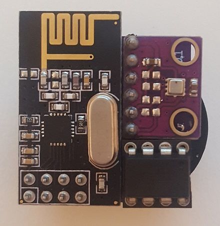
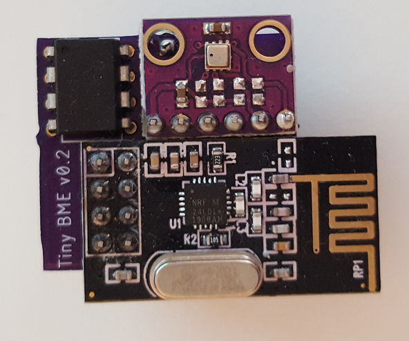
    Right now, I'm going small steps. 2 months back (or so) I assembled the improved version so that the PCB antenna is free from disturbances:
    2.png 1.png
    Next step will be a design with ATtiny in the SMD package (already ordered, as well as a couple of MLCCs in 1206 and 1210 🙂 )


  • @pjeran said in A tiny BME node - BME280 on ATtiny85:

    Has there been any thought with integrating these cores into the mySensors family?

    I've opened an issue for Attiny support on Github but there is no reply yet.


  • @fabyte awesome job. I'm working something similar. Could you share your main program code?


  • @icebob Sure, no thing:

    // -----------------------------------------------------------------------------
    // missing defines
    // -----------------------------------------------------------------------------
    #define SIGRD   RSIG    // Signature Row from Store Program Memory Control and Status Register
    #define EIFR    GIFR    // External/General Interrupt Flag Register
    #define WDTCSR  WDTCR   // WDT Control Register
    // #define TCCR1A TCCR1
    // #define TIFR1 TIFR
    extern void serialEventRun(void) __attribute__((weak));
    
    // -----------------------------------------------------------------------------
    // Configuration
    // -----------------------------------------------------------------------------
    
    // Disable features for reduzing memory footprint
    #define MY_SPLASH_SCREEN_DISABLED
    #define MY_DISABLE_RAM_ROUTING_TABLE_FEATURE
    #define MY_DISABLED_SERIAL
    
    #define MY_NODE_ID          0 
    #define MY_PASSIVE_NODE
    #define MY_DISABLE_REMOTE_RESET
    
    // Enable and select radio type attached
    #define MY_RADIO_RF24
    #define MY_RF24_CE_PIN      NOT_A_PIN
    #define MY_RF24_CS_PIN      4
    
    // BME280 settings
    #define BME_CS_PIN          3
    #define TINY_BME280_SPI
    
    // Sleep Time between reads (in milliseconds)
    #define SLEEP_TIME          120000
    
    // -----------------------------------------------------------------------------
    // MySensors
    // -----------------------------------------------------------------------------
    #include <MySensors.h>
    
    #define CHILD_ID_BME_T    1
    #define CHILD_ID_BME_H    2
    #define CHILD_ID_BME_P    3
    #define CHILD_ID_VOLTAGE  4
    
    MyMessage bmeTempMsg(CHILD_ID_BME_T, V_TEMP);
    MyMessage bmeHumMsg(CHILD_ID_BME_H, V_HUM);
    MyMessage bmePressMsg(CHILD_ID_BME_P, V_PRESSURE);
    MyMessage voltageMsg(CHILD_ID_VOLTAGE, V_VOLTAGE);
    
    // -----------------------------------------------------------------------------
    // BME 280
    // -----------------------------------------------------------------------------
    #define TINY_BME280_SPI_CLOCK   1000000 // 1 MHz
    #include <TinyBME280.h>
    tiny::BME280 bme280;
    
    // -----------------------------------------------------------------------------
    // Implementation
    // -----------------------------------------------------------------------------
    void setupSensor()
    {
    
      bme280.beginSPI(BME_CS_PIN);
    
      // read once to erase initial values
      delay(10);
      bme280.setMode(tiny::Mode::FORCED);
    }
    
    void readAndSendSensorValues()
    {
      bme280.setMode(tiny::Mode::FORCED);
    
      delay(8);
      while(bme280.isMeasuring())
        delay(2); //Hang out while sensor completes the reading
    
      send(bmeTempMsg.set(bme280.readFixedTempC()));
      send(bmeHumMsg.set(bme280.readFixedHumidity()));
      send(bmePressMsg.set(bme280.readFixedPressure()));
    }
    
    void readAndSendBatteryVoltage()
    {
      send(voltageMsg.set(hwCPUVoltage()));
    }
    
    // -----------------------------------------------------------------------------
    // Framework Funktions
    // -----------------------------------------------------------------------------
    void setup()
    {
      setupSensor();
    }
    
    void presentation()
    {
      // Send the sketch version information to the gateway and Controller
      sendSketchInfo("ATtiny Sensor", "1.0");
    
      // Register all sensors to gateway (they will be created as child devices)
      present(CHILD_ID_BME_T, S_TEMP);
      present(CHILD_ID_BME_H, S_HUM);
      present(CHILD_ID_BME_P, S_BARO);
      present(CHILD_ID_VOLTAGE, S_MULTIMETER);
    }
    
    void loop()
    {
      readAndSendSensorValues();
      readAndSendBatteryVoltage();
    
      sleep(SLEEP_TIME);
    }
    
    // -----------------------------------------------------------------------------
    

    Don't forget to set your MY_NODE_ID appropriatly.
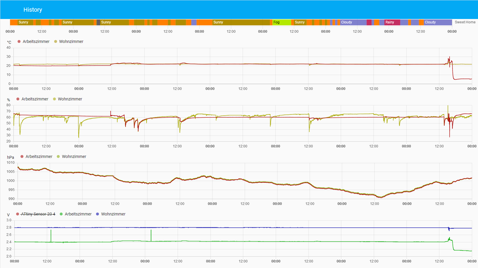
    BME values are sent as fixed point values and are converted to float on controller side.


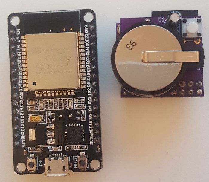
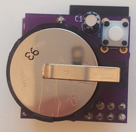
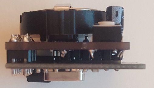
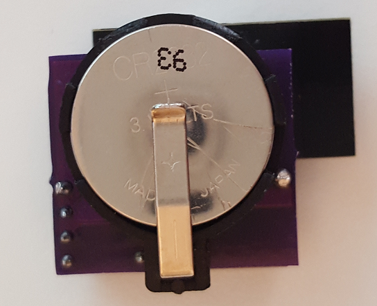
  • Last year I began with the work on the SMD version of the tiny BME node. See pictures here:

    20200624_110630_small.jpg
    20200624_110645_small.jpg

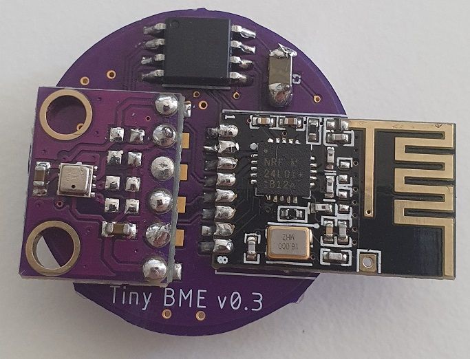
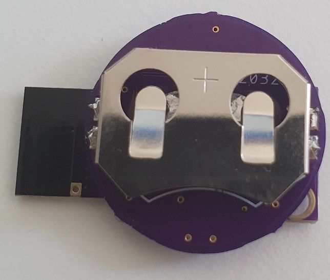
    Problem was that the radio isn't transmitting very reliable and I think I broke it while programming the ATTINY (used 5V instead of 3.3V). I received a few values so I know it is working but I didn't have time to fix it properly which would mean just create a new one.


  • Hardware Contributor

    @fabyte said in A tiny BME node - BME280 on ATtiny85:

    (used 5V instead of 3.3V).

    Usually after doing that the radio still seems to work, but it's not reliable anymore and it is gobbling a lot of power. It is quite vicious as you think it is still working, but the sensor dies quickly...


  • Hi, I try to compile your code change for Mysensors against my Attiny85 but it failed with many errors like

    yHwAVR.cpp:74:2: error: 'EIFR' was not declared in this scope
      EIFR = _BV(interrupt);
    MyHwAVR.cpp:93:26: error: 'WDTCSR' was not declared in this scope
      const uint8_t WDTsave = WDTCSR;
    ...
    

    Please note that my environment is AttinyCore.

    How is your sensors after 1 year? What is your recommendation?


  • Hi @chamroeun-ou
    please try and add the following on top of your main.cpp:

    // -----------------------------------------------------------------------------
    // missing defines
    // -----------------------------------------------------------------------------
    #define SIGRD   RSIG    // Signature Row from Store Program Memory Control and Status Register
    #define EIFR    GIFR    // External/General Interrupt Flag Register
    #define WDTCSR  WDTCR   // WDT Control Register
    // #define TCCR1A TCCR1
    // #define TIFR1 TIFR
    extern void serialEventRun(void) __attribute__((weak));


  • Ok, now it works with your BME-i2c code. not enough memory maybe due to update in AttinyCore which is bigger than your version. I think memory limit is the challenge.


  • To use Attiny, i think there's a need to optimize Mysensor for it as Mysensor consumes the most space of the 8K.


  • @chamroeun-ou I think it's actually quite fascinating that you can fit MySensors in less than 5kb of memory! Consider all the things the library does behind the scenes and that this includes all the required dependencies.

    Try using your BME280 on the SPI bus, which you need anyway for the transceiver. This should shave off about 800 bytes or so. It still fits on ATtinys with 8kb flash using the example sketch posted above (direct link).

    Processing attiny85 (platform: atmelavr; board: attiny85; framework: arduino)
    -------------------------------------------------------------------------------------
    PLATFORM: Atmel AVR (3.3.0) > Generic ATtiny85
    HARDWARE: ATTINY85 8MHz, 512B RAM, 8KB Flash
    PACKAGES:
     - framework-arduino-avr-attiny 1.5.2
     - toolchain-atmelavr 1.70300.191015 (7.3.0)
    RAM:   [=======   ]  65.8% (used 337 bytes from 512 bytes)
    Flash: [==========]  97.2% (used 7960 bytes from 8192 bytes)


  • @BearWithBeard , it's not my code. it is based on @fabyte 's code. Actually, I want to use SHT30 I2C but space is the biggest challenge.

    There's a NRFLite(https://github.com/dparson55/NRFLite) which I think it may save space and can also work with 2 PIN for NRF24 as its created for Attiny but it may not work MySensors without code change.

    My decision now is to use Attiny167 instead but the problem now is it's not working on Mysensors. I try this approach but not work https://github.com/mysensors/MySensors/pull/1485.


  • @chamroeun-ou I'm sorry, I was under the impression that you want to rebuild the OP's project, since there was no mention of different sensors etc.

    Regarding the ATtiny85: How would you have used both SPI and I2C together in the first place? Both are implemented through a single USI and have to share the same OI pins.

    Regarding the ATtiny167: I don't think I have an ATtiny167 at hand currently, so I can't test if it'll actually work, but the OP's example code compiled fine for me. I just had to comment out the the external interrupt flag register redefinition (//#define EIFR GIFR), since it is implemented in the same way it is on the ATmega328P for example.

    Processing attiny167 (platform: atmelavr; board: attiny167; framework: arduino)
    -------------------------------------------------------------------------------
    PLATFORM: Atmel AVR (3.3.0) > Generic ATtiny167
    HARDWARE: ATTINY167 8MHz, 512B RAM, 16KB Flash
    PACKAGES:
     - framework-arduino-avr-attiny 1.5.2
     - toolchain-atmelavr 1.70300.191015 (7.3.0)
    RAM:   [=======   ]  65.0% (used 333 bytes from 512 bytes)
    Flash: [=====     ]  50.5% (used 8274 bytes from 16384 bytes)
    

    The ATtiny167 has dedicated SPI and I2C interfaces and IO pins, so it should be possible to use it as a MySensors node with an SHTC30 sensor. There's plenty of free space, too.


  • @BearWithBeard How do you get it compiled using Mysensors? which code you based on? I got many compiled errors:

    In function 'void hwPowerDown(uint8_t)':
    ../MySensors/hal/architecture/AVR/MyHwAVR.cpp:93:26: error: 'WDTCSR' was not declared in this scope
    const uint8_t WDTsave = WDTCSR;
    ^~~~~~
    
    /../MySensors/hal/architecture/AVR/MyHwAVR.cpp: In function 'uint16_t hwCPUFrequency()':
    /../MySensors/hal/architecture/AVR/MyHwAVR.cpp:305:26: error: 'WDTCSR' was not declared in this scope
    const uint8_t WDTsave = WDTCSR;
    ^~~~~~
    ..MySensors/hal/architecture/AVR/MyMainAVR.cpp: In function 'int main()':
    Arduino/libraries/MySensors/hal/architecture/AVR/MyMainAVR.cpp:34:7: error: 'serialEventRun' was not declared in this scope
    if (serialEventRun) {`
    

    For your question on SPI+IIC on Attiny85, someone has done it successfully by using NRF24 3 PIN so it's left with 2 PIN and use SoftWire library to force BME t use those two PINs.

    Another sketch that I come across is like this: https://github.com/chaeplin/esp8266_and_arduino/tree/master/_51-attiny85-nrf24-lcd-getntp
    But I can't get it to work maybe due to some pullup resistor or something.


  • @chamroeun-ou I used the example sketch from the OP further up in this thread (direct link). The relevant defines are also mentioned in the software section of the first post.

    You need to add the following to your sketch to get rid of the compiler errors:

    #define WDTCSR  WDTCR   // WDT Control Register
    extern void serialEventRun(void) __attribute__((weak));
    

    Note that ATtinys aren't officially supported by MySensors. Although they may work fine in many instances, you are basically on your own if you run into issues. There simply aren't many people who use MySensors on ATtinys.

    You're much more likely to find help if you use a more common MCU, like the ATmega328P. You'll find a list of MySensors-supported architectures on the Overview page.


  • @BearWithBeard said in A tiny BME node - BME280 on ATtiny85:

    Overview page

    @BearWithBeard thanks, now i got my Attiny167+Sht30 working with Mysensors and Mysensor gateway. Next step will be formatting the data for Thingsboard cloud.
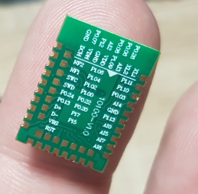

Log in to reply
 

Suggested Topics

0
Online

11.2k
Users

11.1k
Topics

112.5k
Posts