Skip to content
  • MySensors
  • OpenHardware.io
  • Categories
  • Recent
  • Tags
  • Popular
Skins
  • Light
  • Brite
  • Cerulean
  • Cosmo
  • Flatly
  • Journal
  • Litera
  • Lumen
  • Lux
  • Materia
  • Minty
  • Morph
  • Pulse
  • Sandstone
  • Simplex
  • Sketchy
  • Spacelab
  • United
  • Yeti
  • Zephyr
  • Dark
  • Cyborg
  • Darkly
  • Quartz
  • Slate
  • Solar
  • Superhero
  • Vapor

  • Default (No Skin)
  • No Skin
Collapse
Brand Logo
  1. Home
  2. Hardware
  3. ArduinoProMini to nRF24L patch PCB with battery holder and Switch

ArduinoProMini to nRF24L patch PCB with battery holder and Switch

Scheduled Pinned Locked Moved Hardware
3 Posts 2 Posters 2.6k Views 1 Watching
  • Oldest to Newest
  • Newest to Oldest
  • Most Votes
Reply
  • Reply as topic
Log in to reply
This topic has been deleted. Only users with topic management privileges can see it.
  • G Offline
    G Offline
    GaryStofer
    wrote on last edited by GaryStofer
    #1

    I made a little PCB that connects an Arduino ProMini i.e. see here with a nRF24L module and contains two LEDs one Switch and a voltage divider to measure the battery voltage. The board can be ordered from here OSH PCBs for about $3 for 3 PCBs, in the US at least.

    Send me a message if you want the Eagle PCB files.

    See schematic below -- follow notes on schematic -- Do not power with 5V serial adapter, radio will not like 5V.

    Schematic.png 
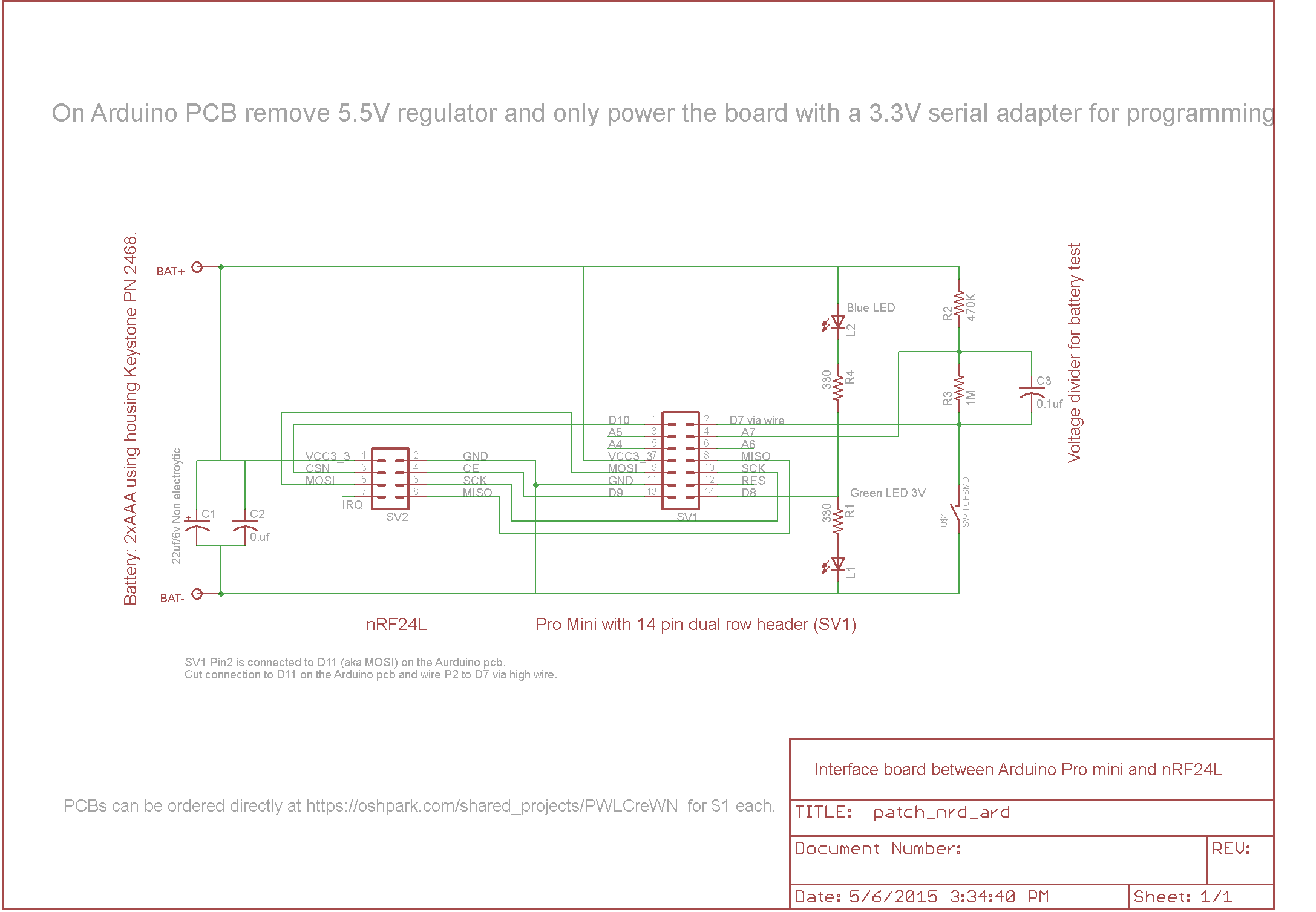
There is a slight silkscreen mistake on the pcb near SV2: Mosi should read Miso.
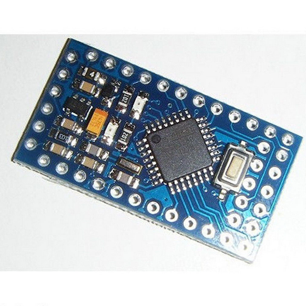
    Pro mini used : ArdProMini.JPG

    1 Reply Last reply
    2
    • DrJeffD Offline
      DrJeffD Offline
      DrJeff
      wrote on last edited by
      #2

      I was just looking at this board on OSHpark last night and was wondering who did it, kudos I might have to do some surface mount soldering, time to build my pickup tool. Your project and another I uploaded to OSHpark required surface mount and I was holding off til now!
      Thanks,
      Jeff

      1 Reply Last reply
      0
      • G Offline
        G Offline
        GaryStofer
        wrote on last edited by
        #3

        You can do it ! Tweezers and magnifying goggles ( from Harbor Fright ) and you are in business.

        Don't forget to set the Arduino to internal clock 8 mhz via fuse settings when rinning at 3V -- Most of them run without it but some might not be happy running 16mhz of the xtal at 3V .Gary

        1 Reply Last reply
        0
        Reply
        • Reply as topic
        Log in to reply
        • Oldest to Newest
        • Newest to Oldest
        • Most Votes


        12

        Online

        11.7k

        Users

        11.2k

        Topics

        113.1k

        Posts


        Copyright 2025 TBD   |   Forum Guidelines   |   Privacy Policy   |   Terms of Service
        • Login

        • Don't have an account? Register

        • Login or register to search.
        • First post
          Last post
        0
        • MySensors
        • OpenHardware.io
        • Categories
        • Recent
        • Tags
        • Popular