How to sleep the Arduino but still have it respond to the Vera?
-
Hi,
I'm trying to save some cpu cycles here! I'm using the pretty much unmodified rfid lock sketch, except I've added code for a LED diode to show if it's armed or disarmed. Since this puppy will only be used when you leave or enter the house, 99% of the time it could sleep. Here is the loop:
void loop() { gw.process(); // Process incomming messages boolean success; uint8_t key[] = { 0, 0, 0, 0, 0, 0, 0 }; // Buffer to store the returned UID uint8_t currentKeyLength; // Length of the UID (4 or 7 bytes depending on ISO14443A card type) // Wait for an ISO14443A type cards (Mifare, etc.). When one is found // 'uid' will be populated with the UID, and uidLength will indicate // if the uid is 4 bytes (Mifare Classic) or 7 bytes (Mifare Ultralight) success = nfc.readPassiveTargetID(PN532_MIFARE_ISO14443A, &key[0], ¤tKeyLength); if (success) { Serial.print("Found tag id: "); for (uint8_t i=0; i < currentKeyLength; i++) { if (i>0) Serial.print(","); Serial.print("0x");Serial.print(key[i], HEX); } for (uint8_t i=currentKeyLength; i < maxKeyLength; i++) { Serial.print(",0x00"); } Serial.println(""); boolean valid = false; // Compare this key to the valid once registered here in sketch for (int i=0;i<keyCount && !valid;i++) { for (int j=0;i<currentKeyLength && !valid;j++) { if (key[j] != validKeys[i][j]) { break; } if (j==currentKeyLength-1) { valid = true; } } } if (valid) { // Switch lock status setLockState(!lockStatus, true); } // Wait for card/tag to leave reader while(nfc.readPassiveTargetID(PN532_MIFARE_ISO14443A, &key[0], ¤tKeyLength)); } gw.sleep(2000); }Using this loop the arduino works great when using the rfid-tag to trigger a change in armed / disarmed, but the arduino does NOT respond to commands from my Vera (UI7).
I think I know what the problem is - basically the Arduino is sleeping when the command from the controller arrives, and thus it can't process it. Changing the last bit of code like this (moving the gw.sleep(2000) only to trigger if an rfid-tag has been read works:
// Wait for card/tag to leave reader while(nfc.readPassiveTargetID(PN532_MIFARE_ISO14443A, &key[0], ¤tKeyLength)); gw.sleep(2000); } }But then again, using this code it doesn't sleep at all except for the 2 seconds 2 times a day when I trigger it. :)
So, how could I have the best of both worlds? I want to let it sleep until 1) there is an incoming command from my Vera or 2) an rfid-tag is recognized. Is it possible?
As always, thanks in advance for any input!
-
If you want to receive commands, you need to keep the nrf24 in receive mode. In this mode the radio consumes about 12mA which is a lot for a battery powered node.
I think it would be possible to send the Arduino to sleep while the radio stays in listening mode, waking up the arduino using the irq pin, but it would still consume the 12mA. -
Hi @fleinze , and thanks for your suggestion. I couldn't find anything in the API or during a quick search of the forum how to do this. Do you have some code for it or?
However, when I checked the API again and I found something I could try, namely the interrupt variable in the sleep function:
bool sleep(int interrupt, int mode, unsigned long ms=0);I'll try something like this and see how it works!
-
Well, that was fast... It didn't work... :(
// Wait for card/tag to leave reader while(nfc.readPassiveTargetID(PN532_MIFARE_ISO14443A, &key[0], ¤tKeyLength)); } gw.sleep(2, CHANGE, 1000); }Am I missing something or am I trying to do something that isn't possible right now?
-
Ok, using the code from http://forum.mysensors.org/topic/1112/how-low-can-arduino-can-go/20 (thanks @funky81 ) I get the Arduino sleeping peacefully while still reacting to interrupts.
Since my rfid doesn't generate an interrupt (attached to A4 and A5) I need to set a timer to wake the little beast up every couple of seconds just to check if there happen to be a tag nearby then. I'll let you know how this turns out! :)
-
Meh...
Trying bits and pieces from all over the web for using the hardware timer, but since I'm not exactly sure what I'm doing when it comes to this level of hardware interaction - well the following crude sketch doesn't work. :)
/* RFID Lock sensor/actuator Henrik Ekblad <henrik.ekblad@mysensors.org> Use RFID tag to lock/unlock a door or trigger a scene on your controller. This example sketch allows you to add an optional relay or solenoid which can be activated/opened by RFID or controller. Use the I2C wiring option for your RFID module and connect to the following Arduino pins. RFID Arduino ----- ------- GND -> GND VCC -> +5V SCL -> A5 SDA -> A4 Use normal wiring for NRF24L01 radio Attach a optional relay or solonoid lock to pin 4 */ #include <MySensor.h> #include <SPI.h> #include <Wire.h> #include <PN532_I2C.h> #include <PN532.h> #include <avr/sleep.h> #include <avr/io.h> #include <avr/interrupt.h> // Add your valid rfid keys here. To find you your key just run sketch; hold your new RFID tag in fron ot the reader; // and copy the key from serial output of this sketch. const uint8_t maxKeyLength = 7; uint8_t validKeys[][maxKeyLength] = { }; int keyCount = sizeof validKeys / maxKeyLength; #define CHILD_ID 99 // Id of the sensor child #define YELLOWLED 5 // Pin for the Yellow led. /*Pin definitions*/ const int lockPin = 4; // (Digital 4) The pin that activates the relay/solenoid lock. bool lockStatus; MySensor gw; MyMessage lockMsg(CHILD_ID, V_LOCK_STATUS); PN532_I2C pn532i2c(Wire); PN532 nfc(pn532i2c); void setup() { pinMode(lockPin, OUTPUT); pinMode(YELLOWLED, OUTPUT); nfc.begin(); uint32_t versiondata = nfc.getFirmwareVersion(); if (! versiondata) { Serial.print("Couldn't find PN53x board"); while (1); // halt } Serial.print("Found NFC chip PN5"); Serial.println((versiondata>>24) & 0xFF, HEX); Serial.print("Firmware ver. "); Serial.print((versiondata>>16) & 0xFF, DEC); Serial.print('.'); Serial.println((versiondata>>8) & 0xFF, DEC); // Set the max number of retry attempts to read from a card // This prevents us from waiting forever for a card, which is // the default behaviour of the PN532. nfc.setPassiveActivationRetries(0x3); // configure board to read RFID tags nfc.SAMConfig(); // Init mysensors library gw.begin(incomingMessage); gw.sendSketchInfo("RFID Lock", "1.0"); gw.present(CHILD_ID, S_LOCK); lockStatus = gw.loadState(0); // Read last lock status from eeprom setLockState(lockStatus, true); // Now set the last known state and send it to controller // initialize Timer1 cli(); // disable global interrupts TCCR1A = 0; // set entire TCCR1A register to 0 TCCR1B = 0; // same for TCCR1B // set compare match register to desired timer count: OCR1A = 15624; // turn on CTC mode: TCCR1B |= (1 << WGM12); // Set CS10 and CS12 bits for 1024 prescaler: TCCR1B |= (1 << CS10); TCCR1B |= (1 << CS12); // enable timer compare interrupt: TIMSK1 |= (1 << OCIE1A); // enable global interrupts: sei(); } void loop() { gw.process(); // Process incomming messages boolean success; uint8_t key[] = { 0, 0, 0, 0, 0, 0, 0 }; // Buffer to store the returned UID uint8_t currentKeyLength; // Length of the UID (4 or 7 bytes depending on ISO14443A card type) // Wait for an ISO14443A type cards (Mifare, etc.). When one is found // 'uid' will be populated with the UID, and uidLength will indicate // if the uid is 4 bytes (Mifare Classic) or 7 bytes (Mifare Ultralight) success = nfc.readPassiveTargetID(PN532_MIFARE_ISO14443A, &key[0], ¤tKeyLength); if (success) { Serial.print("Found tag id: "); for (uint8_t i=0; i < currentKeyLength; i++) { if (i>0) Serial.print(","); Serial.print("0x");Serial.print(key[i], HEX); } for (uint8_t i=currentKeyLength; i < maxKeyLength; i++) { Serial.print(",0x00"); } Serial.println(""); boolean valid = false; // Compare this key to the valid once registered here in sketch for (int i=0;i<keyCount && !valid;i++) { for (int j=0;i<currentKeyLength && !valid;j++) { if (key[j] != validKeys[i][j]) { break; } if (j==currentKeyLength-1) { valid = true; } } } if (valid) { // Switch lock status setLockState(!lockStatus, true); } // Wait for card/tag to leave reader while(nfc.readPassiveTargetID(PN532_MIFARE_ISO14443A, &key[0], ¤tKeyLength)); //gw.sleep(2000); } sleep(); } // Unlocks the door. void setLockState(bool state, bool send){ if (state) { Serial.println("close lock"); digitalWrite(YELLOWLED, HIGH);} else { Serial.println("open lock"); digitalWrite(YELLOWLED, LOW);} if (send) gw.send(lockMsg.set(state)); digitalWrite(lockPin, state); gw.saveState(0,state); lockStatus = state; } void incomingMessage(const MyMessage &message) { // We only expect one type of message from controller. But we better check anyway. if (message.type==V_LOCK_STATUS) { // Change relay state setLockState(message.getBool(), false); // Write some debug info Serial.print("Incoming lock status:"); Serial.println(message.getBool()); } } void sleep(){ // disable ADC ADCSRA = 0; // clear various "reset" flags MCUSR = 0; // allow changes, disable reset WDTCSR = bit (WDCE) | bit (WDE); // set interrupt mode and an interval WDTCSR = bit (WDIE) | bit (WDP3) | bit (WDP0); // set WDIE, and 1 second delay wdt_reset(); // pat the dog set_sleep_mode (SLEEP_MODE_PWR_DOWN); noInterrupts (); // timed sequence follows sleep_enable(); // turn off brown-out enable in software MCUCR = bit (BODS) | bit (BODSE); MCUCR = bit (BODS); interrupts (); // guarantees next instruction executed sleep_cpu (); // cancel sleep as a precaution sleep_disable(); } ISR(TIMER1_COMPA_vect) { boolean success; uint8_t key[] = { 0, 0, 0, 0, 0, 0, 0 }; // Buffer to store the returned UID uint8_t currentKeyLength; // Length of the UID (4 or 7 bytes depending on ISO14443A card type) // Wait for an ISO14443A type cards (Mifare, etc.). When one is found // 'uid' will be populated with the UID, and uidLength will indicate // if the uid is 4 bytes (Mifare Classic) or 7 bytes (Mifare Ultralight) success = nfc.readPassiveTargetID(PN532_MIFARE_ISO14443A, &key[0], ¤tKeyLength); if (success) { Serial.print("Found tag id: "); for (uint8_t i=0; i < currentKeyLength; i++) { if (i>0) Serial.print(","); Serial.print("0x");Serial.print(key[i], HEX); } for (uint8_t i=currentKeyLength; i < maxKeyLength; i++) { Serial.print(",0x00"); } Serial.println(""); boolean valid = false; // Compare this key to the valid once registered here in sketch for (int i=0;i<keyCount && !valid;i++) { for (int j=0;i<currentKeyLength && !valid;j++) { if (key[j] != validKeys[i][j]) { break; } if (j==currentKeyLength-1) { valid = true; } } } if (valid) { // Switch lock status setLockState(!lockStatus, true); } // Wait for card/tag to leave reader while(nfc.readPassiveTargetID(PN532_MIFARE_ISO14443A, &key[0], ¤tKeyLength)); //gw.sleep(2000); } }Help is appreciated...
-
Ok, using the code from http://forum.mysensors.org/topic/1112/how-low-can-arduino-can-go/20 (thanks @funky81 ) I get the Arduino sleeping peacefully while still reacting to interrupts.
Since my rfid doesn't generate an interrupt (attached to A4 and A5) I need to set a timer to wake the little beast up every couple of seconds just to check if there happen to be a tag nearby then. I'll let you know how this turns out! :)
@twosh said:
Since my rfid doesn't generate an interrupt (attached to A4 and A5)
So, your RFID device communicates with I2C, so you may be able to do what you want here.
You could always try to connect to a pin with an interrupt (D2 or D3) by a jumper from A4 or A5. Use a resistor across the pins to limit how much current the interrupt pin sinks.
Attach in a similar way the radio to the other interrupt pin.
so ideally, you are waking your arduino from its slumber on an interrupt from either the RFID scanner or the radio.
Which RFID device are you using?
-
@BulldogLowell Thanks - this sounds like a plan! :)
I'm using this RFID-chip: http://www.ebay.com/itm/271316626820?rmvSB=true
I've got a lot of these resistors lying http://www.ebay.com/itm/220954677122?rmvSB=true but are they too large? 5V / 4,7 kOhm ~ 1 mA, would it trigger? I've got D3 free on my arduino which interrupts, D2 is used by the radio. -
@BulldogLowell Thanks - this sounds like a plan! :)
I'm using this RFID-chip: http://www.ebay.com/itm/271316626820?rmvSB=true
I've got a lot of these resistors lying http://www.ebay.com/itm/220954677122?rmvSB=true but are they too large? 5V / 4,7 kOhm ~ 1 mA, would it trigger? I've got D3 free on my arduino which interrupts, D2 is used by the radio.@twosh said:
@BulldogLowell Thanks - this sounds like a plan! :)
I'm using this RFID-chip: http://www.ebay.com/itm/271316626820?rmvSB=true
I've got a lot of these resistors lying http://www.ebay.com/itm/220954677122?rmvSB=true but are they too large? 5V / 4,7 kOhm ~ 1 mA, would it trigger? I've got D3 free on my arduino which interrupts, D2 is used by the radio.look at the data sheet from your reader.... there is an IRQ pin on the board. You should see how that works.
-
Thanks @BulldogLowell ! I can see that the chip has an IRQ pin and GND among others. SInce I'm not a hardware guy could you tell me if it would be enough to connect the IRQ to my arduino D3-pin? Would I need to connect some other pins as well, e.g. the RFID GND to Arduino GND? (The RFID is already connected to Arduino GND via the 4 pins mentioned in the MySensor guide for connecting the RFID.)
-
Hi all!
Soldered a cable between D3 and the IRQ on the RFID-chip and it seems to have solved my problem. The response time is a bit slow - I need to keep my tag pressed to the RFID-chip for 2-5 seconds before it switches mode. Any idea why that would be? Note that I'm using the sleep function from http://forum.mysensors.org/topic/1112/how-low-can-arduino-can-go/20 and not gw.sleep();
My sketch looks like this:
/* RFID Lock sensor/actuator Henrik Ekblad <henrik.ekblad@mysensors.org> Use RFID tag to lock/unlock a door or trigger a scene on your controller. This example sketch allows you to add an optional relay or solenoid which can be activated/opened by RFID or controller. Use the I2C wiring option for your RFID module and connect to the following Arduino pins. RFID Arduino ----- ------- GND -> GND VCC -> +5V SCL -> A5 SDA -> A4 Use normal wiring for NRF24L01 radio Attach a optional relay or solonoid lock to pin 4 */ #include <MySensor.h> #include <SPI.h> #include <Wire.h> #include <PN532_I2C.h> #include <PN532.h> #include <avr/sleep.h> // Add your valid rfid keys here. To find you your key just run sketch; hold your new RFID tag in fron ot the reader; // and copy the key from serial output of this sketch. const uint8_t maxKeyLength = 7; uint8_t validKeys[][maxKeyLength] = { //Removed my keys here when posting the sketch }; int keyCount = sizeof validKeys / maxKeyLength; #define CHILD_ID 99 // Id of the sensor child #define YELLOWLED 5 // Pin for the Yellow led. /*Pin definitions*/ const int lockPin = 4; // (Digital 4) The pin that activates the relay/solenoid lock. bool lockStatus; MySensor gw; MyMessage lockMsg(CHILD_ID, V_LOCK_STATUS); PN532_I2C pn532i2c(Wire); PN532 nfc(pn532i2c); void setup() { pinMode(lockPin, OUTPUT); pinMode(YELLOWLED, OUTPUT); nfc.begin(); uint32_t versiondata = nfc.getFirmwareVersion(); if (! versiondata) { Serial.print("Couldn't find PN53x board"); while (1); // halt } Serial.print("Found NFC chip PN5"); Serial.println((versiondata>>24) & 0xFF, HEX); Serial.print("Firmware ver. "); Serial.print((versiondata>>16) & 0xFF, DEC); Serial.print('.'); Serial.println((versiondata>>8) & 0xFF, DEC); // Set the max number of retry attempts to read from a card // This prevents us from waiting forever for a card, which is // the default behaviour of the PN532. nfc.setPassiveActivationRetries(0x3); // configure board to read RFID tags nfc.SAMConfig(); // Init mysensors library gw.begin(incomingMessage); gw.sendSketchInfo("RFID Lock", "1.0"); gw.present(CHILD_ID, S_LOCK); lockStatus = gw.loadState(0); // Read last lock status from eeprom setLockState(lockStatus, true); // Now set the last known state and send it to controller } void loop() { gw.process(); // Process incomming messages boolean success; uint8_t key[] = { 0, 0, 0, 0, 0, 0, 0 }; // Buffer to store the returned UID uint8_t currentKeyLength; // Length of the UID (4 or 7 bytes depending on ISO14443A card type) // Wait for an ISO14443A type cards (Mifare, etc.). When one is found // 'uid' will be populated with the UID, and uidLength will indicate // if the uid is 4 bytes (Mifare Classic) or 7 bytes (Mifare Ultralight) success = nfc.readPassiveTargetID(PN532_MIFARE_ISO14443A, &key[0], ¤tKeyLength); if (success) { Serial.print("Found tag id: "); for (uint8_t i=0; i < currentKeyLength; i++) { if (i>0) Serial.print(","); Serial.print("0x");Serial.print(key[i], HEX); } for (uint8_t i=currentKeyLength; i < maxKeyLength; i++) { Serial.print(",0x00"); } Serial.println(""); boolean valid = false; // Compare this key to the valid once registered here in sketch for (int i=0;i<keyCount && !valid;i++) { for (int j=0;i<currentKeyLength && !valid;j++) { if (key[j] != validKeys[i][j]) { break; } if (j==currentKeyLength-1) { valid = true; } } } if (valid) { // Switch lock status setLockState(!lockStatus, true); } // Wait for card/tag to leave reader while(nfc.readPassiveTargetID(PN532_MIFARE_ISO14443A, &key[0], ¤tKeyLength)); //gw.sleep(2000); } sleep(); } // Unlocks the door. void setLockState(bool state, bool send){ if (state) { Serial.println("close lock"); digitalWrite(YELLOWLED, HIGH);} else { Serial.println("open lock"); digitalWrite(YELLOWLED, LOW);} if (send) gw.send(lockMsg.set(state)); digitalWrite(lockPin, state); gw.saveState(0,state); lockStatus = state; } void incomingMessage(const MyMessage &message) { // We only expect one type of message from controller. But we better check anyway. if (message.type==V_LOCK_STATUS) { // Change relay state setLockState(message.getBool(), false); // Write some debug info Serial.print("Incoming lock status:"); Serial.println(message.getBool()); } } void sleep(){ // disable ADC ADCSRA = 0; // clear various "reset" flags MCUSR = 0; // allow changes, disable reset WDTCSR = bit (WDCE) | bit (WDE); // set interrupt mode and an interval WDTCSR = bit (WDIE) | bit (WDP3) | bit (WDP0); // set WDIE, and 1 second delay wdt_reset(); // pat the dog set_sleep_mode (SLEEP_MODE_PWR_DOWN); noInterrupts (); // timed sequence follows sleep_enable(); // turn off brown-out enable in software MCUCR = bit (BODS) | bit (BODSE); MCUCR = bit (BODS); interrupts (); // guarantees next instruction executed sleep_cpu (); // cancel sleep as a precaution sleep_disable(); } -
Hi all!
Soldered a cable between D3 and the IRQ on the RFID-chip and it seems to have solved my problem. The response time is a bit slow - I need to keep my tag pressed to the RFID-chip for 2-5 seconds before it switches mode. Any idea why that would be? Note that I'm using the sleep function from http://forum.mysensors.org/topic/1112/how-low-can-arduino-can-go/20 and not gw.sleep();
My sketch looks like this:
/* RFID Lock sensor/actuator Henrik Ekblad <henrik.ekblad@mysensors.org> Use RFID tag to lock/unlock a door or trigger a scene on your controller. This example sketch allows you to add an optional relay or solenoid which can be activated/opened by RFID or controller. Use the I2C wiring option for your RFID module and connect to the following Arduino pins. RFID Arduino ----- ------- GND -> GND VCC -> +5V SCL -> A5 SDA -> A4 Use normal wiring for NRF24L01 radio Attach a optional relay or solonoid lock to pin 4 */ #include <MySensor.h> #include <SPI.h> #include <Wire.h> #include <PN532_I2C.h> #include <PN532.h> #include <avr/sleep.h> // Add your valid rfid keys here. To find you your key just run sketch; hold your new RFID tag in fron ot the reader; // and copy the key from serial output of this sketch. const uint8_t maxKeyLength = 7; uint8_t validKeys[][maxKeyLength] = { //Removed my keys here when posting the sketch }; int keyCount = sizeof validKeys / maxKeyLength; #define CHILD_ID 99 // Id of the sensor child #define YELLOWLED 5 // Pin for the Yellow led. /*Pin definitions*/ const int lockPin = 4; // (Digital 4) The pin that activates the relay/solenoid lock. bool lockStatus; MySensor gw; MyMessage lockMsg(CHILD_ID, V_LOCK_STATUS); PN532_I2C pn532i2c(Wire); PN532 nfc(pn532i2c); void setup() { pinMode(lockPin, OUTPUT); pinMode(YELLOWLED, OUTPUT); nfc.begin(); uint32_t versiondata = nfc.getFirmwareVersion(); if (! versiondata) { Serial.print("Couldn't find PN53x board"); while (1); // halt } Serial.print("Found NFC chip PN5"); Serial.println((versiondata>>24) & 0xFF, HEX); Serial.print("Firmware ver. "); Serial.print((versiondata>>16) & 0xFF, DEC); Serial.print('.'); Serial.println((versiondata>>8) & 0xFF, DEC); // Set the max number of retry attempts to read from a card // This prevents us from waiting forever for a card, which is // the default behaviour of the PN532. nfc.setPassiveActivationRetries(0x3); // configure board to read RFID tags nfc.SAMConfig(); // Init mysensors library gw.begin(incomingMessage); gw.sendSketchInfo("RFID Lock", "1.0"); gw.present(CHILD_ID, S_LOCK); lockStatus = gw.loadState(0); // Read last lock status from eeprom setLockState(lockStatus, true); // Now set the last known state and send it to controller } void loop() { gw.process(); // Process incomming messages boolean success; uint8_t key[] = { 0, 0, 0, 0, 0, 0, 0 }; // Buffer to store the returned UID uint8_t currentKeyLength; // Length of the UID (4 or 7 bytes depending on ISO14443A card type) // Wait for an ISO14443A type cards (Mifare, etc.). When one is found // 'uid' will be populated with the UID, and uidLength will indicate // if the uid is 4 bytes (Mifare Classic) or 7 bytes (Mifare Ultralight) success = nfc.readPassiveTargetID(PN532_MIFARE_ISO14443A, &key[0], ¤tKeyLength); if (success) { Serial.print("Found tag id: "); for (uint8_t i=0; i < currentKeyLength; i++) { if (i>0) Serial.print(","); Serial.print("0x");Serial.print(key[i], HEX); } for (uint8_t i=currentKeyLength; i < maxKeyLength; i++) { Serial.print(",0x00"); } Serial.println(""); boolean valid = false; // Compare this key to the valid once registered here in sketch for (int i=0;i<keyCount && !valid;i++) { for (int j=0;i<currentKeyLength && !valid;j++) { if (key[j] != validKeys[i][j]) { break; } if (j==currentKeyLength-1) { valid = true; } } } if (valid) { // Switch lock status setLockState(!lockStatus, true); } // Wait for card/tag to leave reader while(nfc.readPassiveTargetID(PN532_MIFARE_ISO14443A, &key[0], ¤tKeyLength)); //gw.sleep(2000); } sleep(); } // Unlocks the door. void setLockState(bool state, bool send){ if (state) { Serial.println("close lock"); digitalWrite(YELLOWLED, HIGH);} else { Serial.println("open lock"); digitalWrite(YELLOWLED, LOW);} if (send) gw.send(lockMsg.set(state)); digitalWrite(lockPin, state); gw.saveState(0,state); lockStatus = state; } void incomingMessage(const MyMessage &message) { // We only expect one type of message from controller. But we better check anyway. if (message.type==V_LOCK_STATUS) { // Change relay state setLockState(message.getBool(), false); // Write some debug info Serial.print("Incoming lock status:"); Serial.println(message.getBool()); } } void sleep(){ // disable ADC ADCSRA = 0; // clear various "reset" flags MCUSR = 0; // allow changes, disable reset WDTCSR = bit (WDCE) | bit (WDE); // set interrupt mode and an interval WDTCSR = bit (WDIE) | bit (WDP3) | bit (WDP0); // set WDIE, and 1 second delay wdt_reset(); // pat the dog set_sleep_mode (SLEEP_MODE_PWR_DOWN); noInterrupts (); // timed sequence follows sleep_enable(); // turn off brown-out enable in software MCUCR = bit (BODS) | bit (BODSE); MCUCR = bit (BODS); interrupts (); // guarantees next instruction executed sleep_cpu (); // cancel sleep as a precaution sleep_disable(); }@twosh said:
Note that I'm using the sleep function from http://forum.mysensors.org/topic/1112/how-low-can-arduino-can-go/20 and not gw.sleep();
I'd try gw.sleep( ) because you can attach the card read function to the interrupt/wakeup event, and avoid the MCU cycling through unnecessary code to get to card read (e.g. gw.process( )).
-
attachInterrupt( ) -
@BulldogLowell Isn't that the part that the MySensors libs (should) take care of?
-
@BulldogLowell Isn't that the part that the MySensors libs (should) take care of?
@marceltrapman said:
@BulldogLowell Isn't that the part that the MySensors libs (should) take care of?
Good point.
Does gw.sleep( ) accept both interrupts?
-
Hi @hek and thanks for the info!
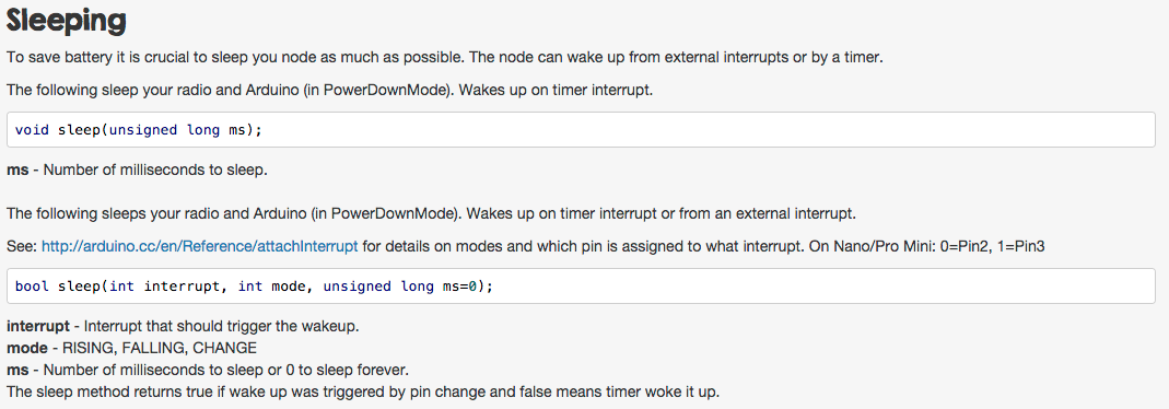
However, I'm not sure that I find anything regarding listening for both D2 and D3-pins in MySensors.h, I only find:
*/**
	 * Sleep (PowerDownMode) the Arduino and radio. Wake up on timer or pin change.
	 * See: http://arduino.cc/en/Reference/attachInterrupt for details on modes and which pin
	 * is assigned to what interrupt. On Nano/Pro Mini: 0=Pin2, 1=Pin3
	 * @param interrupt Interrupt that should trigger the wakeup
	 * @param mode RISING, FALLING, CHANGE
	 * @param ms Number of milliseconds to sleep or 0 to sleep forever
	 * @return true if wake up was triggered by pin change and false means timer woke it up.
	 */
	bool sleep(int interrupt, int mode, unsigned long ms=0);
Which is the same as the documentation, right?
Hello! It looks like you're interested in this conversation, but you don't have an account yet.
Getting fed up of having to scroll through the same posts each visit? When you register for an account, you'll always come back to exactly where you were before, and choose to be notified of new replies (either via email, or push notification). You'll also be able to save bookmarks and upvote posts to show your appreciation to other community members.
With your input, this post could be even better 💗
Register Login