Measuring current
-
Hello
A somewhat stupid question
I have a arduino 3,3 volt without step up or anything. Driven by 2 1,5V batteries.
All positive lines (DHT22 +battery + battery measuring circuit) is connected on Vin pin and all ground cables on ground pin. So fairly simple circuit. Isnt it just to put in the multimeter somewhere in the circuit? Then i read around 4-5mA but the arduino restarts all the time, dont really know why?How to correctly read current on an arduino circuit?
-
Did you connect the multimeter serial to the circuit?
+3 V --> Multimeter --> Circuit --> GND
You can't measure the current if it is connected in parallel to the circuit.
-
Hello
A somewhat stupid question
I have a arduino 3,3 volt without step up or anything. Driven by 2 1,5V batteries.
All positive lines (DHT22 +battery + battery measuring circuit) is connected on Vin pin and all ground cables on ground pin. So fairly simple circuit. Isnt it just to put in the multimeter somewhere in the circuit? Then i read around 4-5mA but the arduino restarts all the time, dont really know why?How to correctly read current on an arduino circuit?
@Fredrik-Carlsson The probable cause is the internal resistance of your multimeter in the low amp setting. Try setting it in A or mA range if the option is there. The voltage drop over the internal resistor (ghost voltage) is probably to high. eg when the internal resistor = 200 Ohm => U=I x R => U= 0.005 x 200 = 1 Volt. When using 3V als power the arduino voltage drops to 2 V (and restarts).
-
Aha, that could probably be the cause then
I have now tried with the following 2 scenarios:
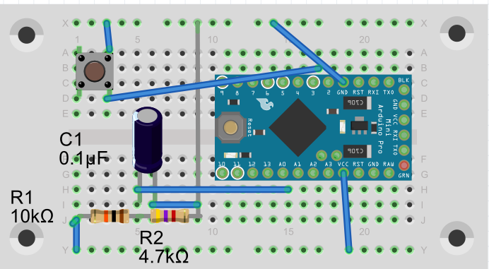
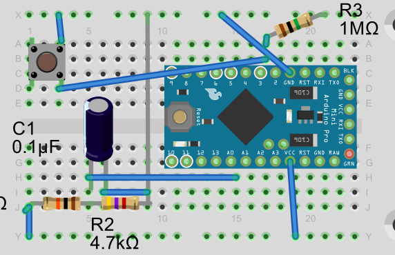
Using internal pullup, then i get the current draw 2,85 mA in sleep, which is quite high?I tried to deactivate the internal pullup and used a 1Mohm resistor as external pullup instead but then the sketch doesnt even start.
As referenced to this thread: http://forum.mysensors.org/topic/1287/door-window-sensor-consuming-more-power-when-closed/3**Or is the cause the fact that I am using 10k/4,7k resistors for battery measurment instead of 1m/470K ? **
So this one is working
And this one is not working
-
Aha, that could probably be the cause then
I have now tried with the following 2 scenarios:
Using internal pullup, then i get the current draw 2,85 mA in sleep, which is quite high?I tried to deactivate the internal pullup and used a 1Mohm resistor as external pullup instead but then the sketch doesnt even start.
As referenced to this thread: http://forum.mysensors.org/topic/1287/door-window-sensor-consuming-more-power-when-closed/3**Or is the cause the fact that I am using 10k/4,7k resistors for battery measurment instead of 1m/470K ? **
So this one is working
And this one is not working
@Fredrik-Carlsson I was referring to the internal resistor of your multimeter... Did you detach the Led of the Arduino? And yes a 10k/4.7k battery measurement circuit draws I = U/R = 3V / 14.700 Ohm = ~ 0.2 mA, which is much more than a sleeping Arduino.
-
@AWI Hello, yes I was aware of that. So it could be possible that configuration no 2 is working, just that it is not possible to measure. .. I will try when I come home. And yes the led is detached. I will also change resistors for the measurement circuit. Just need to order some 470k resistors
-
Hello again.
I just got some new 470k resistors today so i changed out the 10k/4,7k resistors on the battery circuit to 1mohm/470k
The current draw is now 0,63mA when sleeping and 17,6mA when sending.
Especially the sleeping current seem very high. Any ideas to why? -
Hello again.
I just got some new 470k resistors today so i changed out the 10k/4,7k resistors on the battery circuit to 1mohm/470k
The current draw is now 0,63mA when sleeping and 17,6mA when sending.
Especially the sleeping current seem very high. Any ideas to why?@Fredrik-Carlsson Can you post your sketch?
-
#include <MySensor.h> #include <DHT.h> #define CHILD_ID_HUM 0 #define CHILD_ID_TEMP 1 #define CHILD_ID_SWITCH 2 #define BUTTON_PIN 3 #define HUMIDITY_SENSOR_DIGITAL_PIN 4 #define VBAT_PER_BITS 0.003363075 //(1mohm / 470 kohm) Calculated volts per bit from the used battery montoring voltage divider. Internal_ref=1.1V, res=10bit=2^10-1=1023, Eg for 3V (2AA): Vin/Vb=R1/(R1+R2)=470e3/(1e6+470e3), Vlim=Vb/Vin*1.1=3.44V, Volts per bit = Vlim/1023= 0.003363075 #define VMIN 1.9 // Battery monitor lower level. Vmin_radio=1.9V #define VMAX 3.3 // " " " high level. Vmin<Vmax<=3.44 int BATTERY_SENSE_PIN = A0; // select the input pin for the battery sense point unsigned long SLEEP_TIME = 60000; // Sleep time between reads (in milliseconds) MySensor gw; DHT dht; float lastTemp; float lastHum; boolean metric = true; int oldBatteryPcnt = 0; MyMessage msg(CHILD_ID_SWITCH,V_TRIPPED); MyMessage msgHum(CHILD_ID_HUM, V_HUM); MyMessage msgTemp(CHILD_ID_TEMP, V_TEMP); void setup() { analogReference(INTERNAL); gw.begin(); dht.setup(HUMIDITY_SENSOR_DIGITAL_PIN); // Send the Sketch Version Information to the Gateway gw.sendSketchInfo("Humidity", "1.0"); // Setup the button pinMode(BUTTON_PIN,INPUT); // Activate internal pull-up digitalWrite(BUTTON_PIN,HIGH); // Register all sensors to gw (they will be created as child devices) gw.present(CHILD_ID_SWITCH, S_DOOR); gw.present(CHILD_ID_HUM, S_HUM); gw.present(CHILD_ID_TEMP, S_TEMP); metric = gw.getConfig().isMetric; } void loop() { // Get the update value int value = digitalRead(BUTTON_PIN); // Send in the new value gw.send(msg.set(value==HIGH ? 1 : 0)); delay(dht.getMinimumSamplingPeriod()); float temperature = dht.getTemperature(); if (isnan(temperature)) { Serial.println("Failed reading temperature from DHT"); } else if (temperature != lastTemp) { lastTemp = temperature; if (!metric) { temperature = dht.toFahrenheit(temperature); } gw.send(msgTemp.set(temperature, 1)); Serial.print("T: "); Serial.println(temperature); } float humidity = dht.getHumidity(); if (isnan(humidity)) { Serial.println("Failed reading humidity from DHT"); } else if (humidity != lastHum) { lastHum = humidity; gw.send(msgHum.set(humidity, 1)); Serial.print("H: "); Serial.println(humidity); } int sensorValue = analogRead(BATTERY_SENSE_PIN); // Battery monitoring reading // Serial.println(sensorValue); float Vbat = sensorValue * VBAT_PER_BITS; // Serial.print("Battery Voltage: "); Serial.print(Vbat); Serial.println(" V"); //int batteryPcnt = sensorValue / 10; int batteryPcnt = static_cast<int>(((Vbat-VMIN)/(VMAX-VMIN))*100.); // Serial.print("Battery percent: "); Serial.print(batteryPcnt); Serial.println(" %"); if (oldBatteryPcnt != batteryPcnt) { gw.sendBatteryLevel(batteryPcnt); oldBatteryPcnt = batteryPcnt; } gw.sleep(BUTTON_PIN-2, CHANGE, SLEEP_TIME); } -
#include <MySensor.h> #include <DHT.h> #define CHILD_ID_HUM 0 #define CHILD_ID_TEMP 1 #define CHILD_ID_SWITCH 2 #define BUTTON_PIN 3 #define HUMIDITY_SENSOR_DIGITAL_PIN 4 #define VBAT_PER_BITS 0.003363075 //(1mohm / 470 kohm) Calculated volts per bit from the used battery montoring voltage divider. Internal_ref=1.1V, res=10bit=2^10-1=1023, Eg for 3V (2AA): Vin/Vb=R1/(R1+R2)=470e3/(1e6+470e3), Vlim=Vb/Vin*1.1=3.44V, Volts per bit = Vlim/1023= 0.003363075 #define VMIN 1.9 // Battery monitor lower level. Vmin_radio=1.9V #define VMAX 3.3 // " " " high level. Vmin<Vmax<=3.44 int BATTERY_SENSE_PIN = A0; // select the input pin for the battery sense point unsigned long SLEEP_TIME = 60000; // Sleep time between reads (in milliseconds) MySensor gw; DHT dht; float lastTemp; float lastHum; boolean metric = true; int oldBatteryPcnt = 0; MyMessage msg(CHILD_ID_SWITCH,V_TRIPPED); MyMessage msgHum(CHILD_ID_HUM, V_HUM); MyMessage msgTemp(CHILD_ID_TEMP, V_TEMP); void setup() { analogReference(INTERNAL); gw.begin(); dht.setup(HUMIDITY_SENSOR_DIGITAL_PIN); // Send the Sketch Version Information to the Gateway gw.sendSketchInfo("Humidity", "1.0"); // Setup the button pinMode(BUTTON_PIN,INPUT); // Activate internal pull-up digitalWrite(BUTTON_PIN,HIGH); // Register all sensors to gw (they will be created as child devices) gw.present(CHILD_ID_SWITCH, S_DOOR); gw.present(CHILD_ID_HUM, S_HUM); gw.present(CHILD_ID_TEMP, S_TEMP); metric = gw.getConfig().isMetric; } void loop() { // Get the update value int value = digitalRead(BUTTON_PIN); // Send in the new value gw.send(msg.set(value==HIGH ? 1 : 0)); delay(dht.getMinimumSamplingPeriod()); float temperature = dht.getTemperature(); if (isnan(temperature)) { Serial.println("Failed reading temperature from DHT"); } else if (temperature != lastTemp) { lastTemp = temperature; if (!metric) { temperature = dht.toFahrenheit(temperature); } gw.send(msgTemp.set(temperature, 1)); Serial.print("T: "); Serial.println(temperature); } float humidity = dht.getHumidity(); if (isnan(humidity)) { Serial.println("Failed reading humidity from DHT"); } else if (humidity != lastHum) { lastHum = humidity; gw.send(msgHum.set(humidity, 1)); Serial.print("H: "); Serial.println(humidity); } int sensorValue = analogRead(BATTERY_SENSE_PIN); // Battery monitoring reading // Serial.println(sensorValue); float Vbat = sensorValue * VBAT_PER_BITS; // Serial.print("Battery Voltage: "); Serial.print(Vbat); Serial.println(" V"); //int batteryPcnt = sensorValue / 10; int batteryPcnt = static_cast<int>(((Vbat-VMIN)/(VMAX-VMIN))*100.); // Serial.print("Battery percent: "); Serial.print(batteryPcnt); Serial.println(" %"); if (oldBatteryPcnt != batteryPcnt) { gw.sendBatteryLevel(batteryPcnt); oldBatteryPcnt = batteryPcnt; } gw.sleep(BUTTON_PIN-2, CHANGE, SLEEP_TIME); }@Fredrik-Carlsson Looks fine to me.. and you are using the below circuit?
. Maybe a stupid question but do you have a radio connected?
-
Yes i am. but there is mistake in the picture the R3 is connected between Pin 3 and VCC, not ground (pull up resistor).
Then that leaves me hanging a bit because that is way more than I will be comfortable with in terms off battery changes.
Any suggestion what to do?
Hello! It looks like you're interested in this conversation, but you don't have an account yet.
Getting fed up of having to scroll through the same posts each visit? When you register for an account, you'll always come back to exactly where you were before, and choose to be notified of new replies (either via email, or push notification). You'll also be able to save bookmarks and upvote posts to show your appreciation to other community members.
With your input, this post could be even better 💗
Register Login