My other PIR multisensor, on coin cell


  • Hardware Contributor

    Hi 🙂

    I will show you here a board I have roughly drafted last night (one night=one board lol 😊 ). I was bugging on something and wanted to distract my brain with an other thing..and it was too long time that doing this board was tempting me!

    Briefly the context:

    • I have already done a multisensor with PIR on one cell with booster:http://forum.mysensors.org/topic/2951/my-mysx-multisensors-board
      Not released, because I need to fix few things in my files (like maybe remove the ws2812b led which doesn't work well for me at 3v, 8Mhz. Works ok at 16mhz..and few others things). The PIR controller, here is too much exotic, to be a durable sourcable solution. I have enough of these PIR ic for me but not enough for family, friends...
      The new board, presented here, will follow my custom box.
    • I have already made an eval board for PIR which needed some tuning, based on discrete components, no exotic chip: http://forum.mysensors.org/topic/2387/low-power-pir-breakout-board-for-mysensors-and-evaluation
      Based on ST AN4368 app note.
    • and some time ago, I felt in love with this design note from TI, http://www.ti.com/lit/ug/tiduau1a/tiduau1a.pdf
      This design note is a POC for a 10years PIR on coin cell! I felt so in love that I have almost designed an eval board for this crazy CC1310 mcu that I absolutely want to try since so long time (yep, there is RF, but like some people says, read books and follow the 5 master rules, btw I have a spectrum analyzer, not a network one unfortunately! will see what I get. I know I'm maybe too much geeky 🙂
      So, this design appnotes uses the CC1310 which is a very well optimized mcu with optimized power domains for sensors and RF. With a well written software, they get this excellent result of theoretical 10years.

    So, what if we applie these two appnotes to our favorite 328p mcu?? And my board was born 🙂 My first coincell multisensors board (never say never!).

    First, the schematic 😉 I will send it to fabhouse at the end of the week end, to let me more reflexion and see your feedback:

    0_1464434489502_sch.png

    Very basic, isn'it? You see, here, I'm taking another direction:

    • direct battery, no regul so 3.3V max.
    • coincell holder footprint, and two pads to connect a 2xaa/aaa holder for instance to extend the maintenance. This devices, coincell, is designed to be slim, so I would go for aaa lithium.
    • Sensors : the well know SI7021 temperature/humidity, OPT3001 for the light, LHI968 PIR
    • The PIR can be enabled/disabled, thx to a pmosfet
    • Authentication (ATSHA204A signing)
    • Radio : RFM69
    • no external eeprom this time, I will use MYSBootloader on this one
    • debug points for PIR circuits, no potentiometer, I will make it at hand, fixing parts values.
    • reverse polarity protection

    Important note : if you want to take this schematic and make your own...I hope you will take care of the routing on the PIR part because it's very important (false trigger is not far..). This part will, I'm almost sure, need some calibration. Maybe some caps could be removed but for proto I prefer to keep them. Plus it helps for reliability.

    About power consumption:

    You can see on the schematic few notes about this, this should give us, perhaps, roughly, 5-6uA in sleep mode with PIR enabled. No need to disable the radio (it's a camel in sleep mode + i plan to use the listenmode).

    • Few simple maths because it can vary with PIR trigger, coincell quality: but for a coincell of 230mAh, I plan for 200mAh usable energy. Sleep mode :5uA, 30mA in radio transmit during says 40ms (can be more time with signing...), 10 wakeups/hour. That gives us a theoretical estimation of 2.33 years. Not so bad..It can be more if you disable pir for some periods,or less if bad software..
    • that will need some software to improve the sleep mode, blind time, low power during blind time and retrigger..nice challenge 😉

    Few 3d previews, size is 49x30 (so 3 boards on a 10x5cm or 6 on a 10x10, 2mm for vcut)

    0_1460207032902_2016-04-09_14-42-35.jpg

    0_1460207042832_2016-04-09_14-43-18.jpg
    Slim 😉

    One question do you prefer to have PIR High and low signals directly connected to atmel inputs, or like maybe I do, use a nanopower OR gate for one input???

    If you have any remarks, I will be very happy to make some changes (basic) before ordering my pcb. Does it sound good to you?

    Humm, I'm not sure, but @Samuel235 you have here an example of mosfet use to enable power if you want.

    See you soon 🙂


  • Hardware Contributor

    @scalz, I absolutely love this dude! The potential is awesome, i would like to see some nice fancy enclosure being made for this and it would finish an awesome project off nicely.

    I can't answer your question because i'm just, honestly, not advanced enough. However, I don't think you're pushed for IO pins, so having two used wouldn't be too bad IMO unless there is another reason to go with the two inputs over the nanopower nand gate to create one input. I want to learn more about this nand gate process, i'm clueless.

    Your authentication IC, oh my god. I didn't even know these existed but with a little research they seem to be VERY useful little IC's. Could you elaborate why you chose to put it in this module, what is it protecting? Either way i really like the idea from what i can gather from the datasheet.

    I'm going to inspect your PIR circuit later on when i get home. I'm currently using the HC Module and have a transistor on the gnd line to allow me to turn the sensor on and off.

    What is left for mine is:

    1. Add power, tx, rx and err LEDs
    2. Add power line to enable powering externally while programming from a wall socket.
    3. Little things like smoothing caps etc etc.


  • Very interesting !!
    Not for me because SMD components are too small but the schematic is very useful !

    How did you do the 3D view ?
    On the coincell you are using 4 capacitors with different values, it's for filtering ? Is it useful with battery ?

    Thanks for sharing !

    David.


  • Admin

    @Samuel235 said:

    Your authentication IC, oh my god. I didn't even know these existed but with a little research they seem to be VERY useful little IC's. Could you elaborate why you chose to put it in this module, what is it protecting?

    We use it in the MySensors library to send signed messages to and from a node. It's mounted on the Sensebender as well.


  • Hardware Contributor

    @hek said:

    @Samuel235 said:

    Your authentication IC, oh my god. I didn't even know these existed but with a little research they seem to be VERY useful little IC's. Could you elaborate why you chose to put it in this module, what is it protecting?

    We use it in the MySensors library to send signed messages to and from a node. It's mounted on the Sensebender as well.

    So it is for every signed message.... Now that has me. It's going onto my whole room module! This module just gets more and more dense.

    I too am very interested in his schematic to learn from. I'm very intrigued by the motion circuitry.

    I do believe the caps on the batt are for smoothing purposes because a coincell can spike and when it does it drain the batt pretty heavily considering its low capacity value anyway. I doubt that its serving much fltering purpose on here but i may be wrong in assuming this though.


  • Contest Winner

    @scalz I can not express how I felt when I saw this post early this afternoon. I was and still am speechless. At that moment I didn't have the time to reply. This is another genius design, from the MySensors hardware gang. Well done! I'm so proud to be a part of this community! I'll promote MySensors next Thursday when I attend an IoT conference. I think this community deserves way more credits than it gets.

    Just out of curiosity, what do you do for a living? I can't imagine that you're only doing this as a hobby.

    Can't wait to order some of those.


  • Hardware Contributor

    @carlierd : thx. I'm sure you are able 😉 but maybe you have not the good tools yet. No good 0.2mm solder iron? with a magnifier! lol
    This board is 0603. I can't make small things with big 😆 True, it's the sensors part which can be tricky. I own now a reflow so no problem, but I think it can be done with hot air. Plus, if you have a stencil when you have a favorite smd board can be nice, apply it and hot air + solder iron and voilà! lol easy to say..

    @Samuel235 yep atsha204a signing is a mysensors classic 🙂 For your application, I would'nt go for this PIR solution I think, you should keep things like you plan because this schem needs calibration.

    Now about the schematics...good catch, you're right it's very instructive, why I post it.

    I have spent these last months of learning, reading a lot of TI app/design notes for power supply, rf, batteries...I look every week if news, you imagine I'm addict! I have looked at others brand of course for compare.
    I'm a fan of TI stuff, they rock! Very detailed, with concrete application, really great stuff 😉 Just read their notes linked in my post...complete!
    And you will see I have mostly used in this board. But I have changed few things..I apologize 😊 in original they use two "little bit expensive" single opamp. argh! I wanted to keep cost low..but ST has a good/equal double opamp for price of one TI. So I changed it. I keep their very nice low power comparator btw. I added a nand gate to have only one output at the cost 0.9uA but easier to handle then.
    So...why all this speech.
    To share 😉 And it's analog..and some parts value in this schematic could change a little bit during tests, and thx to the design note and my scope! Then when all part value fixed, and software done, that should be pretty reproductible I guess.
    For the caps.. You will see on lot of place. It's a rule I try to apply now when I can and have enough room you can add value. Some are not always useful, but here yes it is important.

    Because:

    • when using coincell, the most important problem is the high internal impedance which increase during transmit for instance. So voltage drop and a decreased battery life too. More if it's for 30mA of TX for instance! oh no our little rfm69! It has been demonstrated that taking care of the power supply, 15mA vs 30mA is less 10% diff life. The most difference is in the quality of the coincell 😉
    • this problem which can create micro spikes too, combined with the nature of the PIR and how it works, analog stuff etc, can make the thing more tricky and create a lot of false trigger.
      So to end this lessons, yes this is for absorbing spikes and storing energy for later to optimize battery life and improve PIR sensor reliabilty, during transmit for instance. Btw there are formula to calculate all of this, I won't put here lol.

    I hope you have found some interesting infos, not too long, thx for reading..I'm still learning, I share my humble tips 🙂


  • Hardware Contributor

    @TheoL 😊

    I work on a project. fun it's for savings and the planet. mostly for big engines... "nothing is created , nothing is lost everything is transformed" 🙂
    I'm not graduated in electronics..I was software archi in real estate management. So imho still a noob (not graduated, not all the basics..) but learn a lot at work, and by myself too, i try 🙂


  • Hardware Contributor

    @scalz, may i ask why you choose to use a MOSFET to control the PIR sensor rather than a Bipolar Junction Transistor?

    From what i understand, a BJT is normally more favored in lower power circuits, but i may be wrong. You got me thinking here so i went and done a little research this morning and stumbled on this webpage. It shows a table around half way down the page comparing the two devices. I'm still thinking maybe i should use a BJT transistor and its simply just a fact that you prefer working with the MOSFETs.

    http://www.electronics-tutorials.ws/transistor/tran_8.html


  • Hardware Contributor

    @samuel235 your link is right, you should understand the opposite you think in fact..mosfets are field effect in voltage which don't need current on the Gate to enable it, so no power consumption compared to BJT which works in the opposite way and need some current to enable it. And if you take a very low Rdson mosfet and use little current in your circuit there will be almost no lost (and no heat too). Which is one of the explanation for the mosfet acting like a reverse protection, near the batt on my circuit too (because it's very low rdson, + small current drain -> better than a diode which can have some voltage drop). But sometimes BJT are useful too, but not my case here. Another note is on my schem I removed the resistor in serie between gate and atmel (in theory it's better to have one, but depending of the application, you can remove it. Or put a 0ohm in case..).

    I'm not a teacher at all but like to share, and with my "english", not easy to translate my thoughts lol! Hope this will help some. True, there are few interesting concept in this schem why I posted it 🙂


  • Hardware Contributor

    Does someone have a thought on this??

    I am thinking that maybe a 4layer could be better for performance. I already designed few simple 4layer. For RF, even if it can be done&tuned on a 2layer (which require more skills), I still think (maybe I'm wrong) that performance is better on a 4layer. Plus it's easier to match impedance. And finally, but not the smallest pros, that ease your life during routing.

    Why I am thinking to this here:

    • I could have a whole gnd plane, still better for our antenna whip. But not a big deal here I think, as rfm69 is already good, and I have tried to have a good gnd plane near antenna.
    • due to the high impedance paths in the circuit, that needs more care on analog trace, 4layer could improve the routing. Vias for some power supply, some via for gnd, and more room and gnd around analog trace + impedance of the board...I would do 1:Signals, 2: full Gnd, 3: Power traces with gnd maybe, 4:signals.
    • have all chance on my side instead of ordering a pcb and then having some troubles...

    Cons:

    • Need to be sure of my design - > a little bit more expensive for a proto. 24$ for 10pcbs 5x5cm. not so bad if I can get 2 boards on a 5x5, but still a little bit more. To reduce cost that would implie I try to fit this on a 24x49 to have 2 boards on 5x5. And I would have to move some passives on bottom..maybe not a big deal here but I wanted to keep everything on top..and maybe remove programming connector for pogopins.

    So it's a small dilemma I thought yesterday...what do you think? I like quality...and the often unbeaten adage says "you have what you pay for"..


  • Hardware Contributor

    @scalz, i'm sorry, i should have acknowledged the fact i understand the low current needs of a mosfet compared to a BJT and how that wouldn't effect my mains powered module. But from the research that i have done i can't really see a reason to choose one over the other and for that reason i think i may go with a MOSFET simply incase i decide to swap to a batt for some reason. One less thing to change. The price is slightly more on a MOSFET compared but we're talking very small when its just one or two per device.

    Would you still choose a MOSFET for mains powering?


  • Hardware Contributor

    @Samuel235 humm..sorry maybe I don't understand well what you want to do..AC, battery?? be careful with AC. So what you want to do with bjt or mosfet, depends on your application. With a schematic that would be easier to understand/help you. We or I can't tell you connect this bjt/mosfet like this or like this without seeing what it implie..


  • Hardware Contributor

    @scalz I will be converting 240VAC to 5VDC on board and then i want to have a 'switch enabled motion circuit' so using either a MOSFET or a BJT Transistor to switch the motion module on and off. I think that the MOSFET is the best as you provide me with this information concerning the 'advantages' of a the MOSFET.


  • I would gladly pay for several of these boards if possible to buy with all components soldered. Any chance of that happening? What would the price /board be in that case?


  • Hardware Contributor

    @Samuel235 ok that should work. for price, I often use CJ2305 (8v rated) or si2323ds (20v). These are low rdson and cheap at aliexpress. Si2323 is a little bit better

    @Cliff-Karlsson thx for your interest. I guess, once the circuit checked, and as there is no exotic chip, that should not be a big deal for the fabhouse I use. They can run small batch if needed. I should check the bom cost too!

    Edit: I have looked briefly at the bom, that might cost to me: 25euros/unit. Without thinking my time and big component lot. Maybe cost could be reduced a little bit by ordering more component. My calculation is based on mouser and aliexpress. Most passives at mouser for quality, and not big difference at ali, it depends which one.
    What kill the cost is the sensor+rf part: opt3001+si7021+LHI968+rfm69. Rfm69cw and lhi968 at ali, for the rest mouser. Buying sensors at ali will not change a lot the price. If i wanted to use sensors breakout and stack on it, arduino style, that would not make a big cost change and that would kill the thickness..The price to pay to have a complete thing...not a simple arduino board..


  • Ok, just a question, is rfm69cw compatible with rfm69(h)w? And what frequencies do you plan to use?


  • Hardware Contributor

    @Cliff-Karlsson
    All rfm69x are software compatible, work with the same lib. Just the footprint or size which change that's all. I'm not planning to use 433..maybe on a Lora node that would make more sense but if I remember right 433mhz is something regulated..I live in Europe, and for residential use, we have to use 868Mhz frequency. And for example, 915mhz for US.
    When ordering radio modules, you have to tell the seller which frequency. If you forget, he should ask you, but better to ask for this during your order. Then, you can set in mysensors, which frequency you want to use. And cut the Wire antenna at the right length (86mm for 868mhz, 82mm for 915mhz). Use a monopole wire (not those with multiple inside). You can coil it (less db but rfm69 is still very good) or if you don't care, let it straight ->more db and range.
    It can be better to solder the antenna directly to the module on antenna pad/hole. Here for instance I have added a hole on pcb, sticked to the antenna pad. It's ok. But sometimes you can see on other boards (I did this too) where the antenna pad is not near. the routing if not well done can detune a little the antenna and have less range.


  • Hardware Contributor

    @scalz, could you just confirm to me that your PIR circuit is working with the P-Channel MOSFET please?

    I'm attempting to get a P-Channel MOSFET in the UK and i just can't source 1 MOSFET below £10. Which, honestly is ridiculous, if i know that your sensor is working as intended I will just design my circuit like this and know it will work without any prototyping.

    However, I'm using the motion module (HC-SR501) and propose to have it setup like normal however, i would have my P-Channel MOSFET on the 5V VCC line and switch it using a digital pin.


  • Hero Member

    @scalz said:

    si2323ds

    SI1869DH is also worth a look as a very nice, general purpose load switch (low volts all the way up to 20v).


  • Hardware Contributor

    @NeverDie said:

    @scalz said:

    si2323ds

    SI1869DH is also worth a look as a very nice, general purpose load switch (low volts all the way up to 20v).

    Not sure why my find function never picked this up to be honest. Thank you for point it out to me, much appreciated 🙂

    Would still like to know if Scalz has this board in working order with the schematic shown.


  • Hero Member

    @scalz
    You may want to take a look at the EX-35R. Its current draw at 3v is just 3.5uA.


  • Hardware Contributor

    @NeverDie thx. I know this sensor. a bit thick. And I had others goals! thin and compact overall with custom box, I like custom box, you can think your assembly, and it's durable source (stl),
    for sharing some parts, and fun a to z training/challenge 🙂

    @Samuel235 not yet. I have received pcb some days ago. but I'm missing few values to assemble pir. I delayed a bit my order because I have other board/bom, and try to have free shipping each time 😉

    but I already use p mosfet on other sensors boards and that works nice...

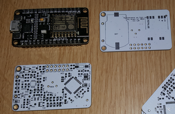
    true, I could have shown you what looks my pcb..so it's white because box will be white and with transparency, I don't want to see the board. But I noticed that each time silkscreen never looks good on white...few ugly things but that will be tiny and thin I think ! I can't wait to assemble it and debug it 🙂
    0_1462640405590_2016-05-07_18-28-53.png


  • Hero Member

    @scalz
    Is the NodeMCU in the photo just for scale, or does it somehow play a role as well?


  • Hardware Contributor

    @NeverDie for scale. and its role is it's bigger than arduio mini, so I cheat 😆 it's still tiny 🙂


  • Hardware Contributor

    I love!

    I was reading the other day about using White silkscreen layer on top, and then the names and values where on the top copper layer (being very careful), it gave the effect of pure white and gold plated. It looked beautiful!


  • Hardware Contributor

    @scalz - Could you take 2 minutes to check this MOSFET for me please, do you think this would work in our application? Once i get the board made i will be using the exact one you have, but i need to breadboard all of this together to learn.


  • Hardware Contributor

    @samuel235 I think you don't need a 17amp mosfet.. for breadboarding, you could use the common TO92 BS250 instead. just a thought 🙂


  • Hardware Contributor

    @scalz, i never chose that MOSFET due to its specs, its just the first i came across at the cheapest price available to me. However, i have found this one now and will only have to pay a small shipping fee. http://www.bitsbox.co.uk/index.php?main_page=product_info&products_id=1018


  • Hero Member

    @scalz said:

    @NeverDie thx. I know this sensor. a bit thick.

    You're doing a great job, but in my case, I'm currently motivated to move quickly and simply "get it done" and move on. Of course, if your project were already finished, I'd be very much interested in it for possible deployment. However, because it's not finished, I think I'd like to mysensor-enable an existing unit, especially if it works well, has long battery life, and is fairly inexpensive. Also, because motion detectors tend to be visible, having attractive industrial design on the enclosure is not unimportant, and that's hard to accomplish on a DIY basis without turning it into a "project."

    So, in the meantime, have you run across any other off-the-shelf motion sensors with good battery life? Or, if not, have you found any with good enclosures? If worse came to worst, I could possibly just make use of a COTS enclosure after upgrading the electronics. For instance, I do have an outdoor Optex motion detector with low(ish) energy requirements and which can run on battery and which, by design, leaves space for inserting my own wireless transceiver.


  • Hardware Contributor

    @Neverdie
    Thx. yep I understand. Each one his way, no way really better I think, your is nice too 😉
    And like I said, I am much more interested in complete design. If I would like something complete, I would buy a commercial products for this kind of application or use the ikea molgan for ceiling. And you're right that PIR tends to be visible, but should not be too much visible too..that's why I prefer smaller/thinner box.
    I'm now working on things which are more expensive to buy..because you can't save big money on this kind of device...

    That said I have no problem to design my custom box 😉 The 3d box for this one is already designed, simple, for a compact 6m lense.
    I enjoy to use Solidworks to design my custom 3d box (for me it's as addicitive as Eagle). I own a 3d printer and filament is cheap! And I would say I'm luckily well equipped to make all sort of diy 🙂 An electronic lab with a reflow oven and nice tools! And a mecha part, with mini lathe, drill press, tig... and more!

    So you see not a problem on my side, just the time, but I have to relativise, my iot thing is not so hurry compared to my daily job. I should assemble one very soon now, things are coming. And this design is well know from TI, I have just adapted it a bit, just another alternative 😉


  • Hero Member

    @scalz

    I see that Olimex has a version of TI's reference design. Currently $16 on Amazon, with Prme delivery. Coincell powered, small, but no enclosure.


  • Hardware Contributor

    What board house did you use for this PCB @scalz?


  • Hardware Contributor

    @Samuel235 elecrow.


  • Hardware Contributor

    @scalz Thanks dude!


  • @NeverDie I see that Olimex has a version of TI's reference design. Currently $16 on Amazon, with Prme delivery. Coincell powered, small, but no enclosure.

    I have looked on AZ, but can't find this version of TI's ref design. Can you provide a link?


  • Hero Member

    @Terrence said in My other PIR multisensor, on coin cell:

    @NeverDie I see that Olimex has a version of TI's reference design. Currently $16 on Amazon, with Prme delivery. Coincell powered, small, but no enclosure.

    I have looked on AZ, but can't find this version of TI's ref design. Can you provide a link?

    That's funny. I thought I had posted the link. Might it have been auto-deleted from my post if it's no longer carried on Amazon?

    Anyhow, at present I'm pursuing the AM612 instead.


  • @NeverDie I have seen reference to the Olimex version of the TI ref design in the past on other forums, but I have never seen a link to it. I have scoured the web for something that will point me to it. Can you point me in the right direction? Thanks.


  • Hero Member

    @Terrence said in My other PIR multisensor, on coin cell:

    @NeverDie I have seen reference to the Olimex version of the TI ref design in the past on other forums, but I have never seen a link to it. I have scoured the web for something that will point me to it. Can you point me in the right direction? Thanks.

    Here you go: https://www.olimex.com/Products/MSP430/Starter/MSP430-PIR/


  • @NeverDie Shows you how good my search was. I think I looked at that, but didn't snap that it had the coin cell on it.
    Thanks.


  • @scalz said in My other PIR multisensor, on coin cell:

    http://forum.mysensors.org/topic/2951/my-mysx-multisensors-board

    @scalz How did your testing / calibration go for the PIR ?
    I would love to pay a fab house to put one of these amazing boards together as I'm sure would many other folk watching your work! 🙂


  • Hardware Contributor

    @tomtastic
    yes I played with different PIR sensor design 🙂

    • The other (old) thread you're linking (with booster and special PIR ic) is working well too, but if i remember I never realeased it completely because I wanted something smaller and lower power..
    • And regarding this thread, it is now located https://www.openhardware.io/view/75/MyMultisensors and it works well too. It is smaller and thinner than the old board.

    I have also another nice design for nrf52 (again, smaller) but actually busy with my job.


  • @scalz

    I have also another nice design for nrf52 (again, smaller) but actually busy with my job.

    Can't wait to see your nrf52 version.


Log in to reply
 

Suggested Topics

  • 87
  • 8
  • 9
  • 2
  • 6
  • 3

0
Online

11.2k
Users

11.1k
Topics

112.5k
Posts