ESP8266 GW with sensors
-
Hi,
I´m using MySensors dev branch 2.0.1 as I heard this one should allow GW´s to have sensors on them and show for controllers.I´m using a NodeMCU with the follow sketch, I can add the GW and it shows up, it presents me with nodes and there I can see S_LIGHT_LEVEL but there is no Name or Value to it. And I do not see any device.
Can anyone see some error in the code?
// Enable debug prints to serial monitor #define MY_DEBUG // Use a bit lower baudrate for serial prints on ESP8266 than default in MyConfig.h #define MY_BAUD_RATE 9600 // Enables and select radio type (if attached) #define MY_RADIO_NRF24 //#define MY_RADIO_RFM69 #define MY_GATEWAY_ESP8266 #define MY_ESP8266_SSID "******" #define MY_ESP8266_PASSWORD "*********" // Enable UDP communication //#define MY_USE_UDP // Set the hostname for the WiFi Client. This is the hostname // it will pass to the DHCP server if not static. // #define MY_ESP8266_HOSTNAME "sensor-gateway" // Enable MY_IP_ADDRESS here if you want a static ip address (no DHCP) #define MY_IP_ADDRESS 10,35,10,70 // If using static ip you need to define Gateway and Subnet address as well #define MY_IP_GATEWAY_ADDRESS 10,35,10,1 #define MY_IP_SUBNET_ADDRESS 255,255,255,0 // The port to keep open on node server mode #define MY_PORT 5003 // How many clients should be able to connect to this gateway (default 1) #define MY_GATEWAY_MAX_CLIENTS 2 // Controller ip address. Enables client mode (default is "server" mode). // Also enable this if MY_USE_UDP is used and you want sensor data sent somewhere. //#define MY_CONTROLLER_IP_ADDRESS 192, 168, 178, 68 // Enable inclusion mode #define MY_INCLUSION_MODE_FEATURE // Enable Inclusion mode button on gateway // #define MY_INCLUSION_BUTTON_FEATURE // Set inclusion mode duration (in seconds) #define MY_INCLUSION_MODE_DURATION 60 // Digital pin used for inclusion mode button #define MY_INCLUSION_MODE_BUTTON_PIN 3 // Set blinking period // #define MY_DEFAULT_LED_BLINK_PERIOD 300 // Flash leds on rx/tx/err // Led pins used if blinking feature is enabled above #define MY_DEFAULT_ERR_LED_PIN 16 // Error led pin #define MY_DEFAULT_RX_LED_PIN 16 // Receive led pin #define MY_DEFAULT_TX_LED_PIN 16 // the PCB, on board LED #if defined(MY_USE_UDP) #include <WiFiUDP.h> #else #include <ESP8266WiFi.h> #endif #include <MySensors.h> #define CHILD_ID_LIGHT 0 #define LIGHT_SENSOR_ANALOG_PIN 0 unsigned long SLEEP_TIME = 30000; // Sleep time between reads (in milliseconds) MyMessage msg(CHILD_ID_LIGHT, V_LIGHT_LEVEL); int lastLightLevel; void setup() { } void presentation() { // Present locally attached sensors here // Send the sketch version information to the gateway and Controller sendSketchInfo("Light Sensor", "1.0"); // Register all sensors to gateway (they will be created as child devices) present(CHILD_ID_LIGHT, S_LIGHT_LEVEL); } void loop() { // Send locally attached sensors data here int16_t lightLevel = (1023-analogRead(LIGHT_SENSOR_ANALOG_PIN))/10.23; Serial.println(lightLevel); if (lightLevel != lastLightLevel) { send(msg.set(lightLevel)); lastLightLevel = lightLevel; } sleep(SLEEP_TIME); } -
Hi,
I´m using MySensors dev branch 2.0.1 as I heard this one should allow GW´s to have sensors on them and show for controllers.I´m using a NodeMCU with the follow sketch, I can add the GW and it shows up, it presents me with nodes and there I can see S_LIGHT_LEVEL but there is no Name or Value to it. And I do not see any device.
Can anyone see some error in the code?
// Enable debug prints to serial monitor #define MY_DEBUG // Use a bit lower baudrate for serial prints on ESP8266 than default in MyConfig.h #define MY_BAUD_RATE 9600 // Enables and select radio type (if attached) #define MY_RADIO_NRF24 //#define MY_RADIO_RFM69 #define MY_GATEWAY_ESP8266 #define MY_ESP8266_SSID "******" #define MY_ESP8266_PASSWORD "*********" // Enable UDP communication //#define MY_USE_UDP // Set the hostname for the WiFi Client. This is the hostname // it will pass to the DHCP server if not static. // #define MY_ESP8266_HOSTNAME "sensor-gateway" // Enable MY_IP_ADDRESS here if you want a static ip address (no DHCP) #define MY_IP_ADDRESS 10,35,10,70 // If using static ip you need to define Gateway and Subnet address as well #define MY_IP_GATEWAY_ADDRESS 10,35,10,1 #define MY_IP_SUBNET_ADDRESS 255,255,255,0 // The port to keep open on node server mode #define MY_PORT 5003 // How many clients should be able to connect to this gateway (default 1) #define MY_GATEWAY_MAX_CLIENTS 2 // Controller ip address. Enables client mode (default is "server" mode). // Also enable this if MY_USE_UDP is used and you want sensor data sent somewhere. //#define MY_CONTROLLER_IP_ADDRESS 192, 168, 178, 68 // Enable inclusion mode #define MY_INCLUSION_MODE_FEATURE // Enable Inclusion mode button on gateway // #define MY_INCLUSION_BUTTON_FEATURE // Set inclusion mode duration (in seconds) #define MY_INCLUSION_MODE_DURATION 60 // Digital pin used for inclusion mode button #define MY_INCLUSION_MODE_BUTTON_PIN 3 // Set blinking period // #define MY_DEFAULT_LED_BLINK_PERIOD 300 // Flash leds on rx/tx/err // Led pins used if blinking feature is enabled above #define MY_DEFAULT_ERR_LED_PIN 16 // Error led pin #define MY_DEFAULT_RX_LED_PIN 16 // Receive led pin #define MY_DEFAULT_TX_LED_PIN 16 // the PCB, on board LED #if defined(MY_USE_UDP) #include <WiFiUDP.h> #else #include <ESP8266WiFi.h> #endif #include <MySensors.h> #define CHILD_ID_LIGHT 0 #define LIGHT_SENSOR_ANALOG_PIN 0 unsigned long SLEEP_TIME = 30000; // Sleep time between reads (in milliseconds) MyMessage msg(CHILD_ID_LIGHT, V_LIGHT_LEVEL); int lastLightLevel; void setup() { } void presentation() { // Present locally attached sensors here // Send the sketch version information to the gateway and Controller sendSketchInfo("Light Sensor", "1.0"); // Register all sensors to gateway (they will be created as child devices) present(CHILD_ID_LIGHT, S_LIGHT_LEVEL); } void loop() { // Send locally attached sensors data here int16_t lightLevel = (1023-analogRead(LIGHT_SENSOR_ANALOG_PIN))/10.23; Serial.println(lightLevel); if (lightLevel != lastLightLevel) { send(msg.set(lightLevel)); lastLightLevel = lightLevel; } sleep(SLEEP_TIME); }@Patrik-Söderström the sketch looks fine to me.
Could you post the serial debug output?Adding Serial.println(lightLevel); after int16_t lightLevel = (1023-analogRead(LIGHT_SENSOR_ANALOG_PIN))/10.23; could also be useful, to verify the value read. The analog pin on ESP8266/NodeMcu is a bit special. For example, it is only able to read voltages up to 1V.
-
The Serial.printIn(lightLeve) is there already.
Serial Monitor
0;255;3;0;9;Client 0: 0;0;3;0;18;PING
-6306
0;255;3;0;9;MCO:SLP:MS=30000,SMS=0,I1=255,M1=255,I2=255,M2=255
0;255;3;0;9;!MCO:SLP:REP
0;255;3;0;9;Client 0: 0;0;3;0;18;PING
Telnet
0;255;3;0;14;Gateway startup complete.
                                      0;255;0;0;18;2.0.1-beta
                                                             0;255;3;0;11;Light Sensor
      0;255;3;0;12;1.0
                      0;0;0;0;16;
                                 0;255;3;0;2;2.0.1-beta
                                                       0;255;3;0;22;14999
                                                                         0;255;3;0;22;25062
           0;255;3;0;22;35146
                             0;255;3;0;22;45277
                                               0;255;3;0;22;55305
                                                                 0;255;3;0;22;65331
   0;255;3;0;22;75360
I´m using a LM393 Light sensor, if that helps.
-
@Patrik-Söderström the sketch looks fine to me.
Could you post the serial debug output?Adding Serial.println(lightLevel); after int16_t lightLevel = (1023-analogRead(LIGHT_SENSOR_ANALOG_PIN))/10.23; could also be useful, to verify the value read. The analog pin on ESP8266/NodeMcu is a bit special. For example, it is only able to read voltages up to 1V.
The Serial.printIn(lightLeve) is there already.
It is. Sorry.
-6306
So your lightLevel is -6306. The value is expected to be between 0 and 100 I think. So we're getting closer to the source of the problem.
-6306 * 10.23 is -64,510.38. int16_t can only hold values between -32,678 and +32,767. 64,510.38 is suspiciously close to 65,535. So my guess is that some calculation overflows.
If the voltage on the analog pin is above 1V I think analogRead() will return 1024. The calculation 1023-1024=-1 which probably is unexpected.
This could be verified by printing the return value of analogRead(LIGHT_SENSOR_ANALOG_PIN)
-
65535 is the value I get when I print analogRead(LIGHT_SENSOR_ANALOG_PIN).
So, then I´m unable to use this light sensor on this NodeMCU? I better set it up on some other node.
Thanks for quick and informative replies :) -
You're welcome. It is still possible to use the sensor if you want to.
The problem lies in that the light sensor gives values of up to 3.3V while the ESP analog pin can only read up to 1V.
The voltage from the light sensor needs to be scaled down with a voltage divider, and the code needs to be changed to subtract from 65535 instead of 1023.
A suitable voltage divider could be 330kohm and 680kohm.
-
You're welcome. It is still possible to use the sensor if you want to.
The problem lies in that the light sensor gives values of up to 3.3V while the ESP analog pin can only read up to 1V.
The voltage from the light sensor needs to be scaled down with a voltage divider, and the code needs to be changed to subtract from 65535 instead of 1023.
A suitable voltage divider could be 330kohm and 680kohm.
Instead of connecting LM393-A0 directly to NodeMcu-A0, connect LM393-A0 to a 680kohm resistor. Connect the other end of the resistor to NodeMcu-A0 AND to a 330khom resistor. Connect the other end of the 330kohm resistor to GND.
It could be that 330/680kohm resistors are too large for the LM393 though. You could try with 330 and 680 ohm (not kohm).
-
Thanks! :)
Yes I ordered a couple of days ago, waiting for them :) Need them for the temp. sensor as well. -
Instead of connecting LM393-A0 directly to NodeMcu-A0, connect LM393-A0 to a 680kohm resistor. Connect the other end of the resistor to NodeMcu-A0 AND to a 330khom resistor. Connect the other end of the 330kohm resistor to GND.
It could be that 330/680kohm resistors are too large for the LM393 though. You could try with 330 and 680 ohm (not kohm).
@mfalkvidd how did you come up with what kind of resistor I should use? Could be good to know in coming project. If you want to share, thanks :)
-
@mfalkvidd how did you come up with what kind of resistor I should use? Could be good to know in coming project. If you want to share, thanks :)
@Patrik-Söderström I used this calculator.
I entered 3.3V as the input voltage and 1.0 as the output voltage. I set R2 to 330 which is a common resistor value.
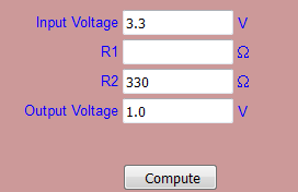
I pressed "Compute" and got a value of 759 for R1:
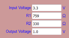
759 ohm is not a resistor value that is available, but I looked at the values in the pack on ebay and saw that the nearest was 680. I entered that in R1 and cleared the output field:
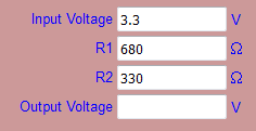 and pressed Compute again. I now got an output of 1.078V which can be seen as close enough to 1V.
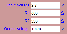
This can of course be done by hand, and is a nice educational task if you want to learn the details :-)
The important part is the ratio between the two resistors. Try with 680,000 and 330,000 in the calculator and you'll see that you get the same output value. However, there is a third component: The LM393. It also has a resistor value. If the resistors in the voltage divider are small compared to the resistor in the LM393, the calculations will be correct. But if the resistors have about the same value as the resistor in the LM393 the calculations must take the LM393 into account. That's why 330 and 680 ohm probably works better than 330kohm and 680kohm.
A caveat with using small resistor values is that they will consume more power. This is important if the sensor is battery powered, but since the NodeMCU generally consumes too much power to run on battery anyway we can ignore the power consumption for now. As long as the resistors are at least 100ohm the used power will be less than what the NodeMCU consumes.
Hello! It looks like you're interested in this conversation, but you don't have an account yet.
Getting fed up of having to scroll through the same posts each visit? When you register for an account, you'll always come back to exactly where you were before, and choose to be notified of new replies (either via email, or push notification). You'll also be able to save bookmarks and upvote posts to show your appreciation to other community members.
With your input, this post could be even better 💗
Register Login