Relay override using togle switch
-
Hello
Thanks again for the coninuous support.
I am setting up my home automation system to control radiator valves and I would like to have the possibility to manually override the operation of any radiator valve at any time.
I found some discussions about this subject but most of them had different requirements than my project.
When the manual mode is selected I would like this to always have preference over any controller or sofware settings. If there is any sofware or hardware issue I still want to be able to quicky switch on or off the radiator valve (to not get frozen while I debug or fix something :-)). This is also important for other people at home in the event of an issue in the host where the controlling is running. I dont want them to wait for me to go back home to re-boot operating system, etc.
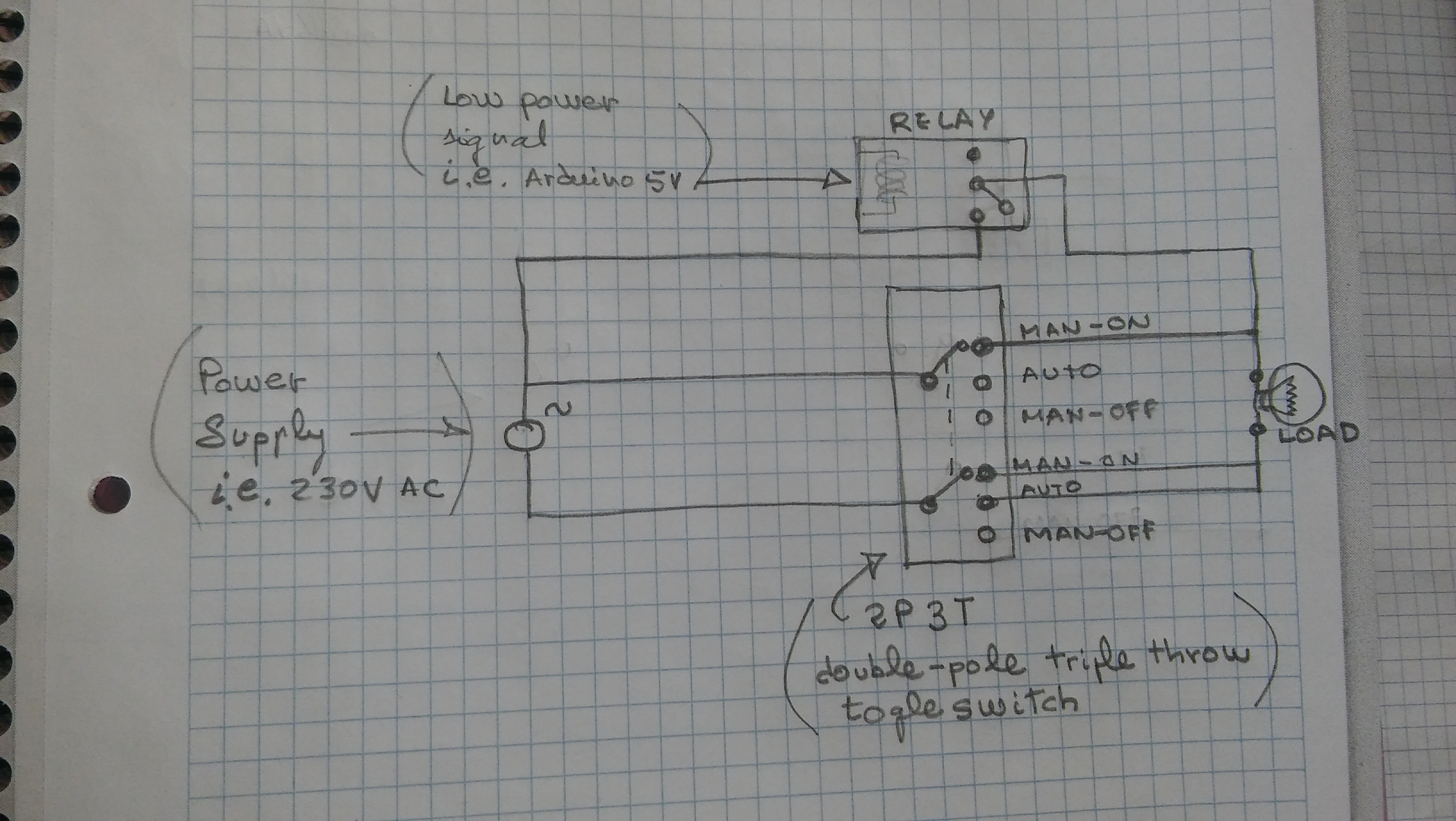
It is also very important to me to be able to set the system back to automatic mode quickly without having to reprogram/ reconfigure or re-initialise anything. I say this because I have seen very interesting solutions which allow manual override by "inverting wires" or inverting control signal, but later on, this could cause that controller may think the radiator is "off" when it is realy "on" (not good).So far I am considering the option of using a 2 pole 3 throw togle switch.
I made a diagram below and I would appreciate any suggestions or feedback about it.
This setting would allow 3 options:- set the radiator manually to to on
- set it to off
- set the system to be managed automatically by the relay (which will be attached to arduino as part of a mysensors node).
As a possible alternative I also though about using two single switches because that hardware would probably be cheaper and easier to find but still my preffered solution would be (if possible) to only use one button.
Many thanks
Best regards
Carlos -
Hello
Thanks again for the coninuous support.
I am setting up my home automation system to control radiator valves and I would like to have the possibility to manually override the operation of any radiator valve at any time.
I found some discussions about this subject but most of them had different requirements than my project.
When the manual mode is selected I would like this to always have preference over any controller or sofware settings. If there is any sofware or hardware issue I still want to be able to quicky switch on or off the radiator valve (to not get frozen while I debug or fix something :-)). This is also important for other people at home in the event of an issue in the host where the controlling is running. I dont want them to wait for me to go back home to re-boot operating system, etc.
It is also very important to me to be able to set the system back to automatic mode quickly without having to reprogram/ reconfigure or re-initialise anything. I say this because I have seen very interesting solutions which allow manual override by "inverting wires" or inverting control signal, but later on, this could cause that controller may think the radiator is "off" when it is realy "on" (not good).So far I am considering the option of using a 2 pole 3 throw togle switch.
I made a diagram below and I would appreciate any suggestions or feedback about it.
This setting would allow 3 options:- set the radiator manually to to on
- set it to off
- set the system to be managed automatically by the relay (which will be attached to arduino as part of a mysensors node).
As a possible alternative I also though about using two single switches because that hardware would probably be cheaper and easier to find but still my preffered solution would be (if possible) to only use one button.
Many thanks
Best regards
Carlos@carlos should work without problem.
I had a similar use case. My rollershutters which do have up, down and stop/neutral positions. I coded it to oversteer the automatic any time. As soon as I press the switch it will do what I want. However at the moment the controller can send another state anytime afterwards.
But what I had coded and set inactive is more or less what you are looking for.
I just check if either button is pressed (up or down) and if so, then the comands from the controller are ignored. this is e.g. if you want to keep them up or down, only in stop/neutral it will accept the comands.
So basically you need to check the state of the buttons. if either A or B is active (in your case on or off) it will not be overruled. only in case of middle position it will accept the comand.However after a few months of tests I am confident that it works.
Cheers,
SJ -
Hello
Thanks again for the coninuous support.
I am setting up my home automation system to control radiator valves and I would like to have the possibility to manually override the operation of any radiator valve at any time.
I found some discussions about this subject but most of them had different requirements than my project.
When the manual mode is selected I would like this to always have preference over any controller or sofware settings. If there is any sofware or hardware issue I still want to be able to quicky switch on or off the radiator valve (to not get frozen while I debug or fix something :-)). This is also important for other people at home in the event of an issue in the host where the controlling is running. I dont want them to wait for me to go back home to re-boot operating system, etc.
It is also very important to me to be able to set the system back to automatic mode quickly without having to reprogram/ reconfigure or re-initialise anything. I say this because I have seen very interesting solutions which allow manual override by "inverting wires" or inverting control signal, but later on, this could cause that controller may think the radiator is "off" when it is realy "on" (not good).So far I am considering the option of using a 2 pole 3 throw togle switch.
I made a diagram below and I would appreciate any suggestions or feedback about it.
This setting would allow 3 options:- set the radiator manually to to on
- set it to off
- set the system to be managed automatically by the relay (which will be attached to arduino as part of a mysensors node).
As a possible alternative I also though about using two single switches because that hardware would probably be cheaper and easier to find but still my preffered solution would be (if possible) to only use one button.
Many thanks
Best regards
Carlos -
Many thanks @parachutes and @Boots33
The valves I am controlling use AC, so for these components I dont worry about polarity.
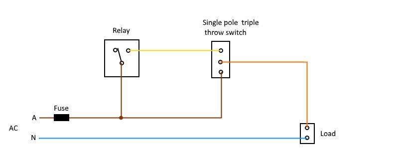
I am having a look at @Boots33 diagram and I think you found exactly what I need. So it is simpler and cheaper than the one I initially thought. I appreciate your imput.
I have seen online some cheap switches with three positions and three terminals ("on/off/on" switch). If I understand correctly, this is what you are suggesting in the diagram. I mean the midle possition leaves all terminals unconnected. This midle possition would mean in my case a "manual mode set to off". The other two possitions being: "manual mode set to on", and the last one "Auto mode" (controlled with domoticz + mysensors + relay).By the way what solfware did you use to make the diagram?. It looks very good to share drawings with other people.
Carlos
-
Many thanks @parachutes and @Boots33
The valves I am controlling use AC, so for these components I dont worry about polarity.
I am having a look at @Boots33 diagram and I think you found exactly what I need. So it is simpler and cheaper than the one I initially thought. I appreciate your imput.
I have seen online some cheap switches with three positions and three terminals ("on/off/on" switch). If I understand correctly, this is what you are suggesting in the diagram. I mean the midle possition leaves all terminals unconnected. This midle possition would mean in my case a "manual mode set to off". The other two possitions being: "manual mode set to on", and the last one "Auto mode" (controlled with domoticz + mysensors + relay).By the way what solfware did you use to make the diagram?. It looks very good to share drawings with other people.
Carlos
@carlos said:
I have seen online some cheap switches with three positions and three terminals ("on/off/on" switch). If I understand correctly, this is what you are suggesting in the diagram. I mean the midle possition leaves all terminals unconnected. This midle possition would mean in my case a "manual mode set to off". The other two possitions being: "manual mode set to on", and the last one "Auto mode" (controlled with domoticz + mysensors + relay).
Yes that is correct. The middle terminal is referred to as the "common" and it can be switched to either of the other terminals or off if the switch is in the center position. If you do an ebay search for "spdt center off" you will find many switches.
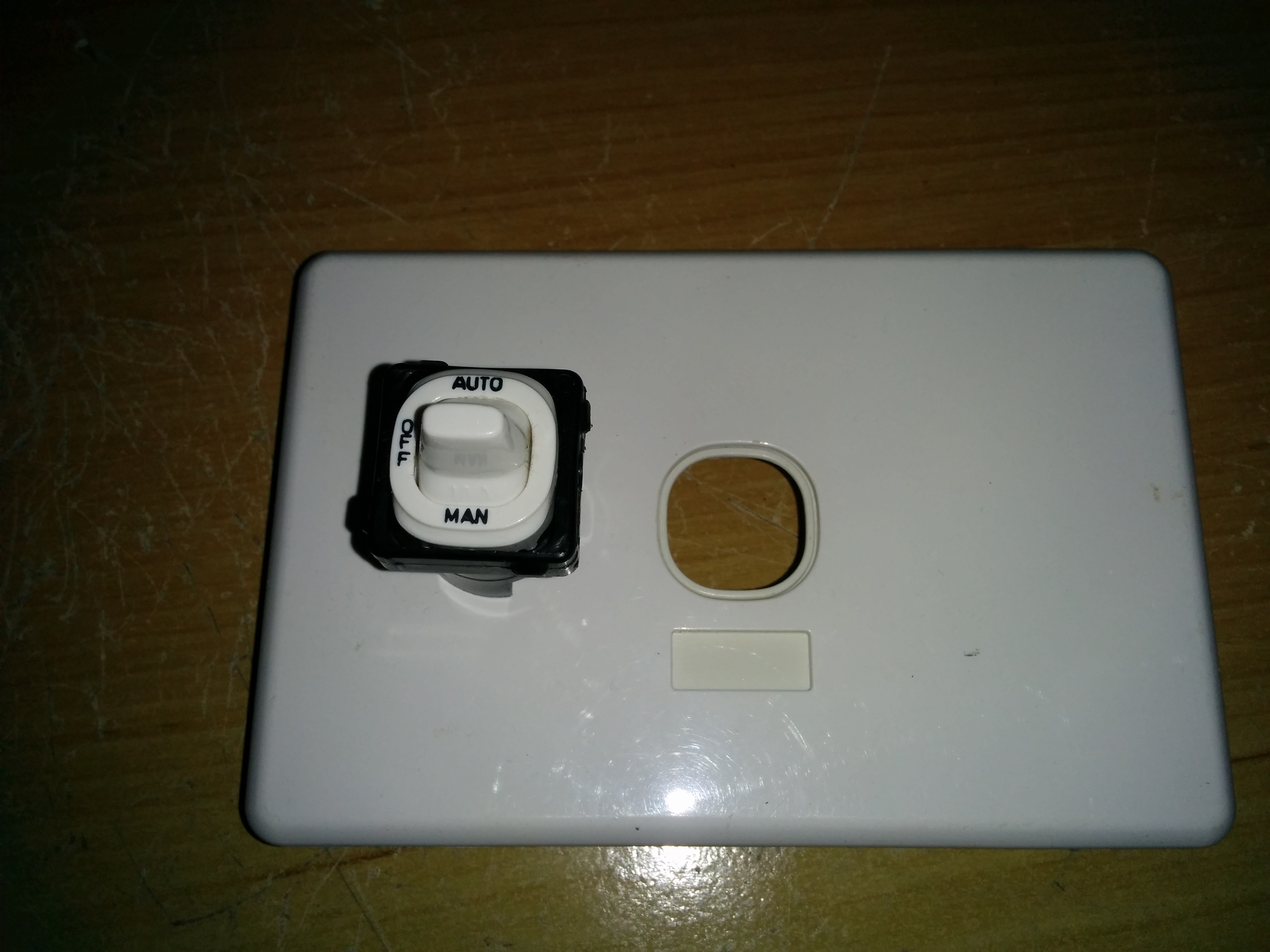
I have used clipsal switches for similar manual/auto setups and they work well, they are a bit expensive though. You can see the middle terminal is marked as common.
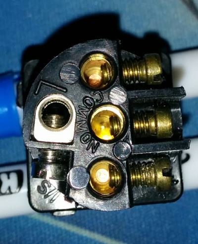
They fit into a standard wall plate and also clearly indicate Auto, off and Manual
By the way what solfware did you use to make the diagram?. It looks very good to share drawings with other people.
I just use a paint program to do the diagrams. The one I use is called paint.net and Gimp is also a popular choice.
Hello! It looks like you're interested in this conversation, but you don't have an account yet.
Getting fed up of having to scroll through the same posts each visit? When you register for an account, you'll always come back to exactly where you were before, and choose to be notified of new replies (either via email, or push notification). You'll also be able to save bookmarks and upvote posts to show your appreciation to other community members.
With your input, this post could be even better 💗
Register Login