Sensor node not working without #define MyDebug
-
Hello,
I have built a sensor node with one of the mysensors examples and my gateway runs the default SerialGateway code without any modification. Sensor node is running on Arduino Mega and Gateway device runs on Arduino Uno and am using the mysensor 2.0. Everything is working properly well but when I tried commenting the #define MY_DEBUG on the gateway code I observe that the sensor node can't seems to work well again and can't successfully connect to the gateway device.Sensor node won't work well if comment the My_Debug code on the gateway.
//#define MY_DEBUGSensor node works well if I uncomment the My_Debug code on the gateway
#define MY_DEBUGMy sensor node #define MY_DEBUG code is uncommented.
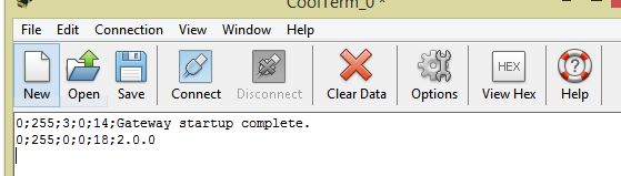
This is the screenshot of the result from the gateway and the sensor node respectively
Result from the sensor node
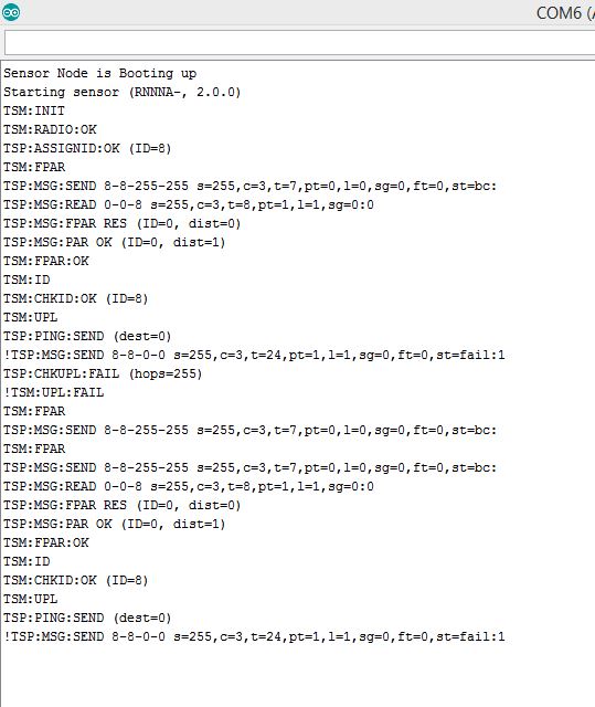
It fails at this stage
TSP:PING:SEND (dest=0)
!TSP:MSG:SEND 8-8-0-0 s=255,c=3,t=24,pt=1,l=1,sg=0,ft=0,st=fail:1
TSP:CHKUPL:FAIL (hops=255)
!TSM:UPL:FAIL
What am I doing wrong? or any fix to make the gateway work with printing out the debug messages.
I will really appreciate the help.
Thank You.
@ayo Hmmm I experienced this also Once with the default repeater node sketch. The radio failed completely when commenting out the my_debug.
However, it went away somehow, so I cannot debug it. It went away after several reuploads of the sketch. So maybe there was just something wrong during programming in my case... -
The Sensor node is being powered by an Arduino Mega 2560 var a USB connection to my pc as source of power. I have a 10uf cap btw the 3.3v and Gnd that powers the nrf24L01+ radio. It's just the normal traditional sensor node setup. Also I have an Led connected to one of the arduino mega pins (pin 4).
@cimba007 said:Can u describe more about your sensor node? What voltage? What speed? General setup?!
-
@ayo Hmmm I experienced this also Once with the default repeater node sketch. The radio failed completely when commenting out the my_debug.
However, it went away somehow, so I cannot debug it. It went away after several reuploads of the sketch. So maybe there was just something wrong during programming in my case...Is it commenting out my_Debug at the gateway side or at the sensor node side. Mine is at the gateway side and the sensor node fails to connect even though my_debug isn't commented out. I even try commenting it out self it doesn't still work either.
@karl261 said:
@ayo Hmmm I experienced this also Once with the default repeater node sketch. The radio failed completely when commenting out the my_debug.
However, it went away somehow, so I cannot debug it. It went away after several reuploads of the sketch. So maybe there was just something wrong during programming in my case... -
I observed similar problem with nodes communication, only in opposite direction, the gateway was fine but two of my nodes required MY_DEBUG enabled to function properly. One of them was completely unreachable without MY_DEBUG or a delay(10) in the loop(), and other node had big problems receiving data (a lot of fail's). I couldn't figure out where the problem was, my assumption is that it is some kind of timing problem, maybe the radio being polled to fast or something... and debug prints certainly add some time to code execution and that kinda solves the problem. But thats only my assumption, I may be completely wrong
-
@delinend Please describe your GW setup, that is:
- HW type
- Frequency / voltage
- Arduino IDE version
- Board def version.
I'd like to reproduce your issue.
@tekka
Last Mysensor 2.0.1-beta
2 Arduino Mini Pro (8Mhz) 3.3V version
2 NRF24l01+ with 47uF caps
Use a 3.6V LiPo battery on both setup's.
IDE 1.6.12I use the standard GatewaySerial.ino and BinarySwitchSleepSensor.ino sketch, where the problem comes, when I disable the MY_DEBUG in the GatewaySerial.ino sketch.
I think the problem is, that the "void loop()" in the GatewaySerial.ino is empty, and the Arduino has a timing problem to the radio, as the loop is running to fast, without doing nothing. If I add delay(10) into the "void loop", it all works fine.
-
@delinend Please describe your GW setup, that is:
- HW type
- Frequency / voltage
- Arduino IDE version
- Board def version.
I'd like to reproduce your issue.
@tekka
Btw. Another problem. If I use the "#define MY_DISABLED_SERIAL" on my GatewaySerial.ino I still get incomming message on the serial port. Ex. temp sendet from a tempsensor here:
6;0;1;0;0,24.5
6;0;1;0;0,24.6
6;0;1;0;0,24.5
6;0;1;0;0,24.4
6;0;1;0;0,24.5 -
Update: If I set my RF24 to MIN (#define RF24_PA_LEVEL RF24_PA_MIN), then my NODE's can fine connect to my Serialgateway, with disabled MY_DEBUG. Hmm that's strange ?!?! So yes, maybe it's a timing problem. Btw. I use 47uF on all NRF24's.
-
@tekka
Btw. Another problem. If I use the "#define MY_DISABLED_SERIAL" on my GatewaySerial.ino I still get incomming message on the serial port. Ex. temp sendet from a tempsensor here:
6;0;1;0;0,24.5
6;0;1;0;0,24.6
6;0;1;0;0,24.5
6;0;1;0;0,24.4
6;0;1;0;0,24.5@delinend said:
@tekka
Btw. Another problem. If I use the "#define MY_DISABLED_SERIAL" on my GatewaySerial.ino I still get incomming message on the serial port. Ex. temp sendet from a tempsensor here:
6;0;1;0;0,24.5
6;0;1;0;0,24.6
6;0;1;0;0,24.5
6;0;1;0;0,24.4
6;0;1;0;0,24.5Well, there is no sense in disabling the serial port on a serial gateway :smirk:
-
@delinend
I also need the AVR board def version - you can find this information in the Boards Manager. -
So I tried to see if I make one last attempt to fix this problem again, I tried the Alex option using a delay(10) in the for loop. So I put a delay(10) in the for loop of my gateway code whoa it works fully well. I guess their is truly a timely issues here and the enable my_debug it's somehow doing a slowing things down work.
But using a delay(10) in the loop isn't really an efficient way though.
@delinend said:I have solved it, with the fix from Alex, with a delay(10) in the loop() :-) Thanks
UPDATE: Using a delay(1) also works for me too
-
@tekka
BN: Unknown board
VID: 10C4
PID EA60
SN: Upload any sketch to obtain itBtw. I use OpTiboot loader
-
@delinend Still not the right thing. Sorry for bugging you with that ;)
You'll find the requested information under:
In Arduino IDE under Tools | Board | Boards Manager => Arduino AVR Boards Built-in by Arduino version 1.6.xx
-
@delinend I've tried your setup but cannot reproduce your issue. Are you on the latest dev branch (from today)? What board did you choose in the settings?
Out of curiosity, please upload this sketch:
#define MY_CORE_ONLY
#define MY_DEBUG
#include <MySensors.h>

void setup() {
  Serial.begin(115200);
  Serial.println("***");
  Serial.print("V=");
  Serial.println(hwCPUVoltage());
  Serial.print("F=");
  Serial.println(hwCPUFrequency());
  Serial.println("***");
}

void loop() {}
and post the serial output.
-
Here the output.
V=3726
F=89
The board name is: [Optiboot] Arduino Pro or Pro Mini (3.3V, 8 MHz) w/ ATmega328
As I use Optiboot bootloader.##############################################################
pro328o.name=[Optiboot] Arduino Pro or Pro Mini (3.3V, 8 MHz) w/ ATmega328
pro328o.upload.tool=avrdude
pro328o.upload.protocol=arduino
pro328o.upload.maximum_size=32256
pro328o.upload.maximum_data_size=2048
pro328o.upload.speed=57600
pro328o.bootloader.tool=avrdude
pro328o.bootloader.low_fuses=0xff
pro328o.bootloader.high_fuses=0xde
pro328o.bootloader.extended_fuses=0xfd
pro328o.bootloader.file=optiboot/optiboot_atmega328.hex
pro328o.bootloader.unlock_bits=0x3F
pro328o.bootloader.lock_bits=0x0F
pro328o.build.mcu=atmega328p
pro328o.build.board=AVR_PRO
pro328o.build.f_cpu=8000000L
pro328o.build.core=arduino
pro328o.build.variant=eightanaloginputs##############################################################
Hello! It looks like you're interested in this conversation, but you don't have an account yet.
Getting fed up of having to scroll through the same posts each visit? When you register for an account, you'll always come back to exactly where you were before, and choose to be notified of new replies (either via email, or push notification). You'll also be able to save bookmarks and upvote posts to show your appreciation to other community members.
With your input, this post could be even better 💗
Register Login