2 AA batteries with step up converter to Vcc pin VS 3 AA batteries to RAW pin
-
Does anyone have the spec sheet for the Chinese step up regulator? I bought a few of these to test
http://www.pololu.com/product/2561 -
@bjornhallberg said:
Don't buy the 3.3V boost / step-up listed in the "store" if you intend to run it on batteries. It has a quiescent power draw of 1mA or so (a modern boost will have 5uA o so by comparison!!), which will drain even your 2xAA batteries in well under two months for sure no matter how lean you run the rest of the circuit. Unfortunately there is no better boost that I've found for sale. You'll have to either wait for the official mysensors hardware lineup which will start with a boost circuit. It should be ready any day now? Right? :-) @axillent
Or you can run most of the sensors on just 2xAA (in series) directly, no boost or anything in-between. Sure the voltage will soon drop below 3V but it will most likely take months and most sensors as well as the nrf24 and arduino pro mini will cope with that. You wont be able to suck every last drop out of the batteries but it shouldn't be too bad. Far better than the 1mA quiescent.
If you had a boost, and limited space, you could also power your sensor node with just one AA. Like the official battery powered sensor node that is forthcoming.
If you're handy with SMD and can source a few capacitors and inductors you could always build some yourself. Texas Instruments has free samples available if you want to try. Still trying to get mine to work though :-/ I can't figure out what I did wrong here. I thought about starting thread about it but I'm holding out for the official modules.
Btw. Battery Calculator: http://oregonembedded.com/batterycalc.htm
In testing, using a sensor with 2 DS18B20's, I had problems almost immediately (at about 4 days). As the batteries dropped below 2.3vdc I started to see skewed temp. results.
Now in my tests I was using rechargeable EBL 2800mAh NiMH batteries, so that my have been part of the problem. With only 1 mod (removal of the Arduino LED, I'm getting about ~4 months. My sketches are not stock, and I'm only sending updates when changes exceed .5 delta.
@ServiceXp Are those NiMH batteries low self discharge (LSD) or not? I looked them up on Amazon and saw someone had tested them and found they were some sort of middle ground. Better than most NiMH but not LSD per se. Now I was about to rant about how bad NiMH batteries are but after actually looking up discharge curves of Alkaline and at least LSD NiMH I'm not so sure. If prices have come down a bit (have they?) they could work as well as Alkaline. Maybe. I haven't really found a test yet that uses as slow discharge as we are using here (understandable perhaps as it would take a great deal of time to complete). When doing something like a constant discharge of several hundred mA, the 1.5V starting point of the Alkaline will soon drop below the 1.2V starting point for NiMH, but in our case with extremely slow discharge, Alkaline should still hold their edge for a good portion of their lifespan.
@cygnus Yeah, the DS18B20 doesn't seem as forgiving as some other sensors. So running off of AA directly may have its downsides, but at least you haven't bought anything you may regret.
@m26872 70uA sounds phenomenal. I'm going by this old thread though:
http://forum.mysensors.org/topic/171/efficiency-of-voltage-boosters@Rek A bit fuzzy on the quiescent power but should be better than the Ebay ones. Would be interesting to see some results. Still, I'm holding out for the official modules.
-
@ServiceXp Are those NiMH batteries low self discharge (LSD) or not? I looked them up on Amazon and saw someone had tested them and found they were some sort of middle ground. Better than most NiMH but not LSD per se. Now I was about to rant about how bad NiMH batteries are but after actually looking up discharge curves of Alkaline and at least LSD NiMH I'm not so sure. If prices have come down a bit (have they?) they could work as well as Alkaline. Maybe. I haven't really found a test yet that uses as slow discharge as we are using here (understandable perhaps as it would take a great deal of time to complete). When doing something like a constant discharge of several hundred mA, the 1.5V starting point of the Alkaline will soon drop below the 1.2V starting point for NiMH, but in our case with extremely slow discharge, Alkaline should still hold their edge for a good portion of their lifespan.
@cygnus Yeah, the DS18B20 doesn't seem as forgiving as some other sensors. So running off of AA directly may have its downsides, but at least you haven't bought anything you may regret.
@m26872 70uA sounds phenomenal. I'm going by this old thread though:
http://forum.mysensors.org/topic/171/efficiency-of-voltage-boosters@Rek A bit fuzzy on the quiescent power but should be better than the Ebay ones. Would be interesting to see some results. Still, I'm holding out for the official modules.
@bjornhallberg
I admit that 70uA sounds a bit to good to be true. The figures in that thread says min 500uA for "china 3.3V without led) I think I'll have to do some more measuring to confirm my results. So far I've only used my Fluke 87 in uA-range with burden voltage "display value times 100uV", which hasn't been calibrated since due date in 2012. -
@ServiceXp Are those NiMH batteries low self discharge (LSD) or not? I looked them up on Amazon and saw someone had tested them and found they were some sort of middle ground. Better than most NiMH but not LSD per se. Now I was about to rant about how bad NiMH batteries are but after actually looking up discharge curves of Alkaline and at least LSD NiMH I'm not so sure. If prices have come down a bit (have they?) they could work as well as Alkaline. Maybe. I haven't really found a test yet that uses as slow discharge as we are using here (understandable perhaps as it would take a great deal of time to complete). When doing something like a constant discharge of several hundred mA, the 1.5V starting point of the Alkaline will soon drop below the 1.2V starting point for NiMH, but in our case with extremely slow discharge, Alkaline should still hold their edge for a good portion of their lifespan.
@cygnus Yeah, the DS18B20 doesn't seem as forgiving as some other sensors. So running off of AA directly may have its downsides, but at least you haven't bought anything you may regret.
@m26872 70uA sounds phenomenal. I'm going by this old thread though:
http://forum.mysensors.org/topic/171/efficiency-of-voltage-boosters@Rek A bit fuzzy on the quiescent power but should be better than the Ebay ones. Would be interesting to see some results. Still, I'm holding out for the official modules.
@bjornhallberg I would agree; while these EBL's are probably the best NiMH batteries I've ever used, they probably are still not quite as good as good Alkaline's.
-
The reference for mini pro says:
Input Voltage 3.35 -12 V (3.3V model) or 5 - 12 V (5V model) -
@ServiceXp Are those NiMH batteries low self discharge (LSD) or not? I looked them up on Amazon and saw someone had tested them and found they were some sort of middle ground. Better than most NiMH but not LSD per se. Now I was about to rant about how bad NiMH batteries are but after actually looking up discharge curves of Alkaline and at least LSD NiMH I'm not so sure. If prices have come down a bit (have they?) they could work as well as Alkaline. Maybe. I haven't really found a test yet that uses as slow discharge as we are using here (understandable perhaps as it would take a great deal of time to complete). When doing something like a constant discharge of several hundred mA, the 1.5V starting point of the Alkaline will soon drop below the 1.2V starting point for NiMH, but in our case with extremely slow discharge, Alkaline should still hold their edge for a good portion of their lifespan.
@cygnus Yeah, the DS18B20 doesn't seem as forgiving as some other sensors. So running off of AA directly may have its downsides, but at least you haven't bought anything you may regret.
@m26872 70uA sounds phenomenal. I'm going by this old thread though:
http://forum.mysensors.org/topic/171/efficiency-of-voltage-boosters@Rek A bit fuzzy on the quiescent power but should be better than the Ebay ones. Would be interesting to see some results. Still, I'm holding out for the official modules.
@bjornhallberg As I suspected this was wrong! I now measure total sleep mode current draw ~1mA (with one DHT at Vbat 3.1V. My project thread/post is now updated. Sorry.
-
The reference for mini pro says:
Input Voltage 3.35 -12 V (3.3V model) or 5 - 12 V (5V model)@epierre said:
The reference for mini pro says:
Input Voltage 3.35 -12 V (3.3V model) or 5 - 12 V (5V model)Does anyone know what is the power loss of the on board voltage regulator (to compare to the loss from the step up converter)?
My thought process was that maybe using 3 AAs (or perhaps 4) and letting the on board regulator step the voltage down would result in a longer time until battery changes being needed. I thought maybe even as the batteries discharge and their output decreased, it would still be overall be higher than 2 AAs and therefore require less current to achieve the regulated 3.3V and therefore a slower discharge rate.
If power losses from step up converter are comparable to power losses from on board regulator having more batteries seems like it would obviously increase the run time, increase the size of the sensor (although wouldn't require space for the step up converter), decrease intial cost, possible increase long term cost. Right?
-
@epierre said:
The reference for mini pro says:
Input Voltage 3.35 -12 V (3.3V model) or 5 - 12 V (5V model)Does anyone know what is the power loss of the on board voltage regulator (to compare to the loss from the step up converter)?
My thought process was that maybe using 3 AAs (or perhaps 4) and letting the on board regulator step the voltage down would result in a longer time until battery changes being needed. I thought maybe even as the batteries discharge and their output decreased, it would still be overall be higher than 2 AAs and therefore require less current to achieve the regulated 3.3V and therefore a slower discharge rate.
If power losses from step up converter are comparable to power losses from on board regulator having more batteries seems like it would obviously increase the run time, increase the size of the sensor (although wouldn't require space for the step up converter), decrease intial cost, possible increase long term cost. Right?
@hooraysimpsons The "official" Pro Mini is supposed to have a Micrel MIC5205 allegedly.
http://www.micrel.com/_PDF/mic5205.pdf
Marked "KB33". Same as on my cheap clone. On paper it has phenomenal quiescent current draw.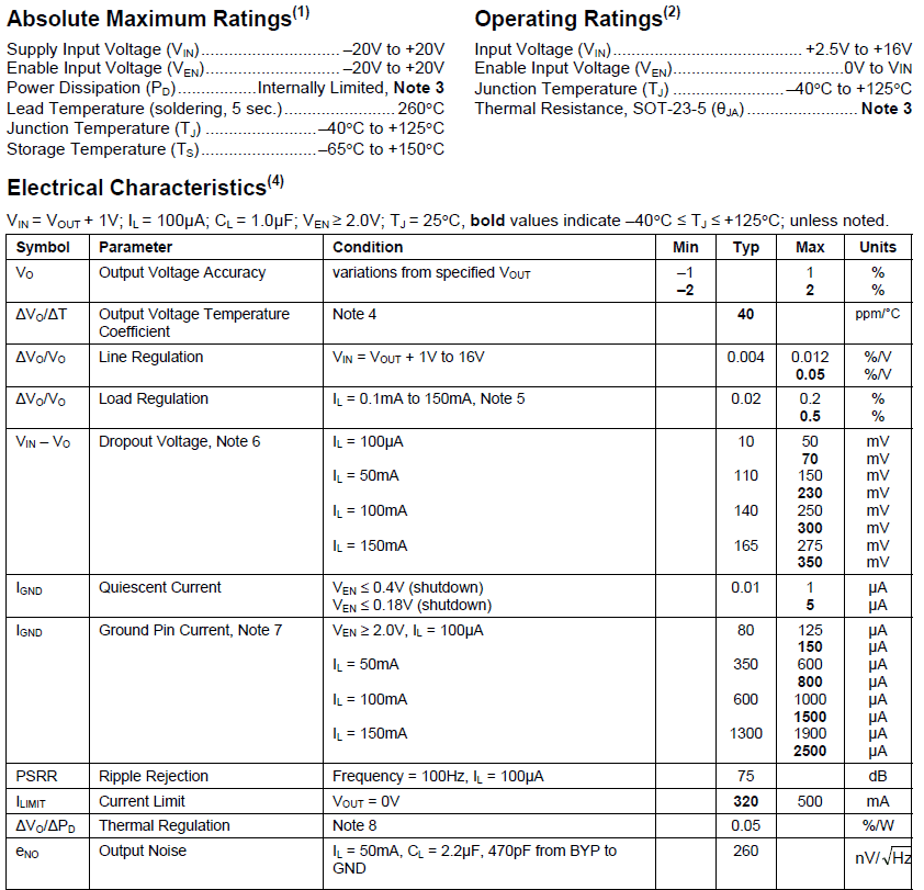
In practice, people are not as impressed:
https://www.sparkfun.com/products/11114#comment-504d47b1ce395fb72d000001
Don't know what to make of this. But it still seems miles better than the useless Ebay boost? Our own build page claims you can save 220uA by removing or disabling the regulator. Is that figure so high only because the regulator is getting back-fed otherwise as you bypass it?Bottom line, are we 100% sure the on-board regulator is so crappy that it in fact has to be circumvented? I mean, for inputs when using 3+ AA batteries? I mean, personally I'd rather not use so many batteries and bulk up the sensors, plus the extra cost of batteries would soon pay for an external boost I guess.
-
I have now set up a test node with 4 AA to the raw-pin (mic5205) and with the pwr-led removed. External loads are one DS18B20 and a 5+1Mohm battery monitoring circuit (and the radio of course). With battery voltage 5.82V (not fresh batteries) I get 115-120uA in sleepmode. Not bad. Power <25% of my 2AA china-stepup nodes. On the downside are a little worse (higher) low-limit voltage and little less available 3.3V-power to sensors. And I don't think the different final voltage level would matter since it is near the end of "the curve".
Considering Vin = Vout +1V = 4.3V according to the datasheet above, I'm sure 3 AAs not will be using enough of their working range. But 4 AA looks like a good choice to me, if space isn't an issue.
It would be interesting to see the economy with 4 AAA batteries. Calculations anyone? -
I have now set up a test node with 4 AA to the raw-pin (mic5205) and with the pwr-led removed. External loads are one DS18B20 and a 5+1Mohm battery monitoring circuit (and the radio of course). With battery voltage 5.82V (not fresh batteries) I get 115-120uA in sleepmode. Not bad. Power <25% of my 2AA china-stepup nodes. On the downside are a little worse (higher) low-limit voltage and little less available 3.3V-power to sensors. And I don't think the different final voltage level would matter since it is near the end of "the curve".
Considering Vin = Vout +1V = 4.3V according to the datasheet above, I'm sure 3 AAs not will be using enough of their working range. But 4 AA looks like a good choice to me, if space isn't an issue.
It would be interesting to see the economy with 4 AAA batteries. Calculations anyone?@m26872 Interesting findings! A not at all unreasonable setup either. As to AAA ... I don't know. They're less than half of an AA typically in terms of capacity usually. At the same per unit price. Still you'd probably get up to a year on 4xAAA. Or close enough. For just a few sensors I could probably live with this.
-
@m26872 Interesting findings! A not at all unreasonable setup either. As to AAA ... I don't know. They're less than half of an AA typically in terms of capacity usually. At the same per unit price. Still you'd probably get up to a year on 4xAAA. Or close enough. For just a few sensors I could probably live with this.
@bjornhallberg So the next exercise would be to compare the 3AA setup with the 4AAA setup? My first thought is that it could pretty even but with some different features in terms of space, duration and price.
-
Don't buy the 3.3V boost / step-up listed in the "store" if you intend to run it on batteries. It has a quiescent power draw of 1mA or so (a modern boost will have 5uA o so by comparison!!), which will drain even your 2xAA batteries in well under two months for sure no matter how lean you run the rest of the circuit. Unfortunately there is no better boost that I've found for sale. You'll have to either wait for the official mysensors hardware lineup which will start with a boost circuit. It should be ready any day now? Right? :-) @axillent
Or you can run most of the sensors on just 2xAA (in series) directly, no boost or anything in-between. Sure the voltage will soon drop below 3V but it will most likely take months and most sensors as well as the nrf24 and arduino pro mini will cope with that. You wont be able to suck every last drop out of the batteries but it shouldn't be too bad. Far better than the 1mA quiescent.
If you had a boost, and limited space, you could also power your sensor node with just one AA. Like the official battery powered sensor node that is forthcoming.
If you're handy with SMD and can source a few capacitors and inductors you could always build some yourself. Texas Instruments has free samples available if you want to try. Still trying to get mine to work though :-/ I can't figure out what I did wrong here. I thought about starting thread about it but I'm holding out for the official modules.
Btw. Battery Calculator: http://oregonembedded.com/batterycalc.htm
@bjornhallberg said:
Don't buy the 3.3V boost / step-up listed in the "store" if you intend to run it on batteries. It has a quiescent power draw of 1mA or so (a modern boost will have 5uA o so by comparison!!), which will drain even your 2xAA batteries in well under two months for sure no matter how lean you run the rest of the circuit. Unfortunately there is no better boost that I've found for sale. You'll have to either wait for the official mysensors hardware lineup which will start with a boost circuit. It should be ready any day now? Right? :-) @axillent
Well, if you wanted to test now you could try the JeeLabs AA board: http://moderndevice.com/product/jeelabs-aa-power-board/
Or:
http://lowpowerlab.com/powershield/I'm waiting for the MySensors boost board tho.
-
Does anyone have the spec sheet for the Chinese step up regulator? I bought a few of these to test
http://www.pololu.com/product/2561@Rek said:
Does anyone have the spec sheet for the Chinese step up regulator? I bought a few of these to test
http://www.pololu.com/product/2561My guess is that it is or is similar to the 2108A in SOT89-3 described here:
http://fullmany.com/Upload/file/ME2108%20series-E8_0.pdf
Hello! It looks like you're interested in this conversation, but you don't have an account yet.
Getting fed up of having to scroll through the same posts each visit? When you register for an account, you'll always come back to exactly where you were before, and choose to be notified of new replies (either via email, or push notification). You'll also be able to save bookmarks and upvote posts to show your appreciation to other community members.
With your input, this post could be even better 💗
Register Login