best approach to add MySensors Node to an existing smoke detector?
-
I have several smoke detectors around in my house, all driven by a 9 Volt block but without a radio. I think about the best approach to add a MySensors node to it. I do not have the schematics of the smoke detector.
I want to use the 9 Volt block, so the node needs a voltage regulator.
The node should draw as less current as possible, so connecting the buzzer from the smoke detector via an optocoupler to the MySensors node will need far too much current. What about a zener? What about a voltage divider (resistors) to reduce buzzer voltage to Arduino pin level?
Any other idea? Thanks in advance -
I have several smoke detectors around in my house, all driven by a 9 Volt block but without a radio. I think about the best approach to add a MySensors node to it. I do not have the schematics of the smoke detector.
I want to use the 9 Volt block, so the node needs a voltage regulator.
The node should draw as less current as possible, so connecting the buzzer from the smoke detector via an optocoupler to the MySensors node will need far too much current. What about a zener? What about a voltage divider (resistors) to reduce buzzer voltage to Arduino pin level?
Any other idea? Thanks in advance@dirkc The buzzer is most likely only powered when an alarm sounds ;-) Leakage in the optocoupler "transistor" is mostly in the nano ampere (nA) region when off. So I would suggest you measure the voltage over the buzzer when sounding (protect your ears!). Add a series resistor (estimate 300 ohm to 1k) with the optocoupler LED.
On the MySensor node side 700k to 1M as collector pull-up to the optocoupler and attach to INT0 or 1 and treat like a Motion node. Power the node with a capable LDO (mcp1700 or similar, watch the input voltage (9v)). -
I have several smoke detectors around in my house, all driven by a 9 Volt block but without a radio. I think about the best approach to add a MySensors node to it. I do not have the schematics of the smoke detector.
I want to use the 9 Volt block, so the node needs a voltage regulator.
The node should draw as less current as possible, so connecting the buzzer from the smoke detector via an optocoupler to the MySensors node will need far too much current. What about a zener? What about a voltage divider (resistors) to reduce buzzer voltage to Arduino pin level?
Any other idea? Thanks in advance@dirkc I'm trying to do something similar here . I started from a chinese smoke detector with an unknown xc5010dw chip which revealed to be similar to the following http://www.nxp.com/assets/documents/data/en/data-sheets/MC145010.pdf. Not sure if you have something similar but my chip has a I/O port on pin 7 which goes high when the alarm triggers which should be way easier then attaching to the buzzer. For powering on the arduino from the 9v power supply, we probably need a MCP1703 or something similar I guess (the MCP1700 that I have available do not go over 6v as input)
-
@dirkc I'm trying to do something similar here . I started from a chinese smoke detector with an unknown xc5010dw chip which revealed to be similar to the following http://www.nxp.com/assets/documents/data/en/data-sheets/MC145010.pdf. Not sure if you have something similar but my chip has a I/O port on pin 7 which goes high when the alarm triggers which should be way easier then attaching to the buzzer. For powering on the arduino from the 9v power supply, we probably need a MCP1703 or something similar I guess (the MCP1700 that I have available do not go over 6v as input)
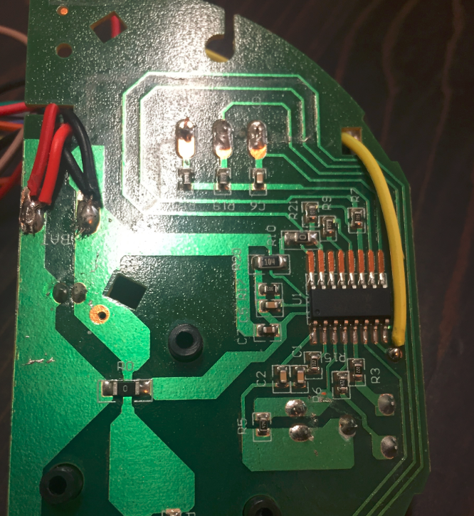
Quick update on this one: I've used a pro mini with the voltage regulator still on board just to test, connected raw and ground to the smoke detector power supply, connected the I/O pin with a 100k/47k voltage divider to the arduino's pin 3, used the same code of a motion sensor and put the board to sleep. When I push the test button the board wakes up from the interrupt and reports back so it works to me. I now need a better LDO than the AMS1117 for the 9v->3.3v conversion. Picture below in case can be useful to somebody else.
-
@user2684 good approach, I'll have to check my smoke detector, which is a German brand
https://www.amazon.de/Merten-547019-ARGUS-Rauchmelder-polarweiß/dp/B000ONMOGQ
Don't know if the schematic is available.@dirkc probably yours is different but you can try having a look at the MCU, from what I read around different vendors are likely to use just a few of those dedicated MCUs. My I/O port was also very easy to see. Alternatively you may have a look at this in case you missed it: http://harizanov.com/2014/07/diy-internet-of-things-fire-alarm/
-
@dirkc probably yours is different but you can try having a look at the MCU, from what I read around different vendors are likely to use just a few of those dedicated MCUs. My I/O port was also very easy to see. Alternatively you may have a look at this in case you missed it: http://harizanov.com/2014/07/diy-internet-of-things-fire-alarm/
-
@user2684 , I have same smoke sensor as you (as per picture you posted). How did you end with this? I'm experience many false smoke alarms, no matter what resistors/diodes I use.
Sorry for reopen such old thread!
Hi, @rvendrame after a while the board stopped reporting to the gateway, not sure why, while the smoke detector is up and running. It is still in my todo list to do some troubleshooting, if I'll discover more and I'll let for sure know.
Thanks
Hello! It looks like you're interested in this conversation, but you don't have an account yet.
Getting fed up of having to scroll through the same posts each visit? When you register for an account, you'll always come back to exactly where you were before, and choose to be notified of new replies (either via email, or push notification). You'll also be able to save bookmarks and upvote posts to show your appreciation to other community members.
With your input, this post could be even better 💗
Register Login