Beginner - what is wrong
-
@tbowmo I will try to install all the drivers & IDE on diferent comp tomorrow. I already did the downgrade from 1.8 because of the note "Arduino IDE 1.5.x & 1.6.x compatible." in SB tech specs.
Anyway thanks for your help. I will have to invest more hours yet to reinvent the wheel but it is fine to have somebody to consult with. -
So I have tried it on the different computer and the results are the same.
This is what I did:
- download ide 1.8 here https://www.arduino.cc/en/main/software & install
- download CP CP2102 win 10 drivers here https://www.silabs.com/products/development-tools/software/usb-to-uart-bridge-vcp-drivers
- install mysensors libraries in IDE via manage library internal tool
- add https://raw.githubusercontent.com/mysensors/ArduinoBoards/master/package_mysensors.org_index.json to IDE
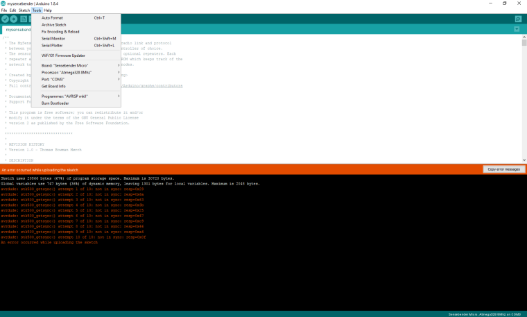
- select Sensebender micro board, COM6 (the only available), Programmer AVRISP.mkII
- add necessary libraries to compile the sensebender micro sketch as described here https://www.mysensors.org/about/arduino#optional---install-external-mysensors-examples - via creating zip files and add zip library file to sketch. Necessary libraries were SI7021 + sha204 + RunningAverage
- compile and upload the basic sketch from here https://www.openhardware.io/view/1/Sensebender-Micro
Result is: stk500_getsync() attempt 7 of 10: not in sync: resp=0xdb
-
Wait a moment, you choose AVRISP.mkII ? That shouldn't be necessary, as it is only needed if you ever want to upload a new bootloader (and then you need a different programming adapter as well)
You are using the build in arduino programming tool to download? (Second icon from left, in the top menu)
@tbowmo Yes, second icon from the left (or Ctrl+U).
By pressing Project Upload via programmer (in menu Project or Ctrl+Shift+U) the result is little bit different - no stk500_getsync() attempt 7 of 10: not in sync: resp=0xdb error just uncommented Upload error. -
When you have chosen SenseBender Micro as target, which sub variant did you choose? (8Mhz, or 1Mhz?) Can't remember if there are any differences in baudrate.. And I'm not at my arduino dev. machine right now. You should choose the 8Mhz as target.
Also could you check soldering of the board? (specially around the reset line, capacitor, resistors, atmega328)
That is the last things that I could think about right now..
-
I have selected 8 MHz. This is what it looks like by me
This is what I did today - got another sensebender micro (SBM) board, soldered jumpers, connected again. Then I measured the conductivity between DTR pin on CP2102 chip and capacitor on DTR wire on SBM. It shall be conected via my wires and it was correctly connected.
Then I run the compillation again and the result is the same - not in sync. So I feel I have replaced everything but still getting the same error.
-
Hello!
I was hoping I would find a solution here as I basically have the same problem. I ordered two Sensebender Micros like two months ago and flashing a sketch onto them is failing with the same
avrdude: stk500_getsync() attempt X of Y: not in syncerror. (Noteworthy: I only assembled one Sensebender so far, I haven't tried the second one).In my case: I am using ArchLinux with kernel 4.13, so drivers should not be the issue here. I am using this FTDI flash module and the same USB cable for other projects and was able to successfully flash an ESP 8266, a Arduino Pro Mini and a Nano.
Executing the self-test on the Sensebender Micro does also work and with serial attached I even get the output that all tests have passed. Still, i am not able to flash something onto this device using the IDE. Instead of selecting the board option
Sensebender Micro(using both 8 and 1 MHz options) I even tried some odd choices likeArduino Pro MiniorArduino Nano. Nevertheless, none of those did work.Regarding FTDI to Sensebender connection: VCC <-> VCC, GND <-> GND, RX and TX are swapped. I even tried replacing the cables and tried to connect DTR without luck.
Any further hints are appreciated, thank you.
-
-
Only thing that is left, that I can think about, is if itead had somehow forgotten to write the bootloader..
But then again, I have supplied them with a binary including both bootloader, and default sensebender micro sketch, so it should have the bootloader. Unless they have made some mistakes..
I haven't bought any sensebenders for the last couple of years, so unfortunately I can't verify this.
-
Thank you for you input. I had luck and we have an AVRISP mk2 lying around in my company that I can borrow for the weekend. So my plan would be to try to re-flash DualOptiboot first or another bootloader (maybe the stock Arduino Pro Mini one) in further tries and see if this helps.
The only two things I am trying to figure out in this very moment are:
- in which direction the ISP cable has to be mounted so that nothing is damaged
- and I do not know yet for sure if the AVRISP mk2 is actually suppyling power or not to the board (for cases where e.g. it may feed 5 volts).
-
Okay, I have soldered the second Sensebender too and tried to burn the bootloader via Arduino IDE onto both devices. The verbose log was the following:
/home/x/.arduino15/packages/arduino/tools/avrdude/6.3.0-arduino9/bin/avrdude -C/home/x/.arduino15/packages/arduino/tools/avrdude/6.3.0-arduino9/etc/avrdude.conf -v -patmega328p -cstk500v2 -Pusb -Uflash:w:/home/x/.arduino15/packages/MySensors/hardware/avr/1.0.1/bootloaders/DualOptiboot/optiboot_atmega328_pro_8MHz.hex:i -Ulock:w:0x0F:m

avrdude: Version 6.3, compiled on Jan 17 2017 at 11:00:16
         Copyright (c) 2000-2005 Brian Dean, http://www.bdmicro.com/
         Copyright (c) 2007-2014 Joerg Wunsch

         System wide configuration file is "/home/x/.arduino15/packages/arduino/tools/avrdude/6.3.0-arduino9/etc/avrdude.conf"
         User configuration file is "/home/x/.avrduderc"
         User configuration file does not exist or is not a regular file, skipping

         Using Port                    : usb
         Using Programmer              : stk500v2
avrdude: usbdev_open(): Found AVRISP mkII, serno: redacted
         AVR Part                      : ATmega328P
         Chip Erase delay              : 9000 us
         PAGEL                         : PD7
         BS2                           : PC2
         RESET disposition             : dedicated
         RETRY pulse                   : SCK
         serial program mode           : yes
         parallel program mode         : yes
         Timeout                       : 200
         StabDelay                     : 100
         CmdexeDelay                   : 25
         SyncLoops                     : 32
         ByteDelay                     : 0
         PollIndex                     : 3
         PollValue                     : 0x53
         Memory Detail                 :

                                  Block Poll               Page                       Polled
           Memory Type Mode Delay Size  Indx Paged  Size   Size #Pages MinW  MaxW   ReadBack
           ----------- ---- ----- ----- ---- ------ ------ ---- ------ ----- ----- ---------
           eeprom        65    20     4    0 no       1024    4      0  3600  3600 0xff 0xff
           flash         65     6   128    0 yes     32768  128    256  4500  4500 0xff 0xff
           lfuse          0     0     0    0 no          1    0      0  4500  4500 0x00 0x00
           hfuse          0     0     0    0 no          1    0      0  4500  4500 0x00 0x00
           efuse          0     0     0    0 no          1    0      0  4500  4500 0x00 0x00
           lock           0     0     0    0 no          1    0      0  4500  4500 0x00 0x00
           calibration    0     0     0    0 no          1    0      0     0     0 0x00 0x00
           signature      0     0     0    0 no          3    0      0     0     0 0x00 0x00

         Programmer Type : STK500V2
         Description     : Atmel STK500 Version 2.x firmware
         Programmer Model: AVRISP mkII
         Hardware Version: 1
         Firmware Version Master : 1.23
         Vtarget         : 3.0 V
         SCK period      : 8.00 us

avrdude: AVR device initialized and ready to accept instructions

Reading | ################################################## | 100% 0.00s

avrdude: Device signature = 0x1e950f (probably m328p)
avrdude: NOTE: "flash" memory has been specified, an erase cycle will be performed
         To disable this feature, specify the -D option.
avrdude: erasing chip
avrdude: reading input file "/home/x/.arduino15/packages/MySensors/hardware/avr/1.0.1/bootloaders/DualOptiboot/optiboot_atmega328_pro_8MHz.hex"
avrdude: writing flash (32768 bytes):

Writing | ################################################## | 100% 0.00s

avrdude: 32768 bytes of flash written
avrdude: verifying flash memory against /home/x/.arduino15/packages/MySensors/hardware/avr/1.0.1/bootloaders/DualOptiboot/optiboot_atmega328_pro_8MHz.hex:
avrdude: load data flash data from input file /home/x/.arduino15/packages/MySensors/hardware/avr/1.0.1/bootloaders/DualOptiboot/optiboot_atmega328_pro_8MHz.hex:
avrdude: input file /home/x/.arduino15/packages/MySensors/hardware/avr/1.0.1/bootloaders/DualOptiboot/optiboot_atmega328_pro_8MHz.hex contains 32768 bytes
avrdude: reading on-chip flash data:

Reading | ################################################## | 100% 0.00s

avrdude: verifying ...
avrdude: 32768 bytes of flash verified
avrdude: reading input file "0x0F"
avrdude: writing lock (1 bytes):

Writing | ################################################## | 100% 0.01s

avrdude: 1 bytes of lock written
avrdude: verifying lock memory against 0x0F:
avrdude: load data lock data from input file 0x0F:
avrdude: input file 0x0F contains 1 bytes
avrdude: reading on-chip lock data:

Reading | ################################################## | 100% 0.00s

avrdude: verifying ...
avrdude: WARNING: invalid value for unused bits in fuse "lock", should be set to 1 according to datasheet
This behaviour is deprecated and will result in an error in future version
You probably want to use 0xcf instead of 0x0f (double check with your datasheet first).
avrdude: 1 bytes of lock verified

avrdude done.  Thank you.
Interesting in this log is the warning about the invalid value for some fuse bits...
Flashing a sketch after re-burning the bootloader sadly did not work, the same
not in syncerror occured again. Next, I tried to burn the bootloader using the board setting of the Arduino Pro Mini (3.3v, 8mhz). Strange enough, this does not work anymore now, yielding a pretty generic error:avrdude: stk500v2_command(): command failed avrdude: stk500v2_program_enable(): bad AVRISPmkII connection status: Unknown status 0x00 avrdude: initialization failed, rc=-1 Double check connections and try again, or use -F to override this check.I do not know, I can only assume that maybe burning another bootloader does not work because of the invalid value warning while burning the default bootloader. I also tried to burn the original Optiboot without success.
I just have this problem with "programming" solved. I bought this USBISP programmer, downloaded libUSBk drivers from here and pushed it into SBmicro via programmer USBasp. I don't know why but from some reason two UART programmers were not working.
It may save frustration and time to somebody in future.
-
I just have this problem with "programming" solved. I bought this USBISP programmer, downloaded libUSBk drivers from here and pushed it into SBmicro via programmer USBasp. I don't know why but from some reason two UART programmers were not working.
It may save frustration and time to somebody in future.
Thanks, I just ordered the same programmer. Let's see if this is working. How did you wire the programmer to the Sensebender? Just asking because the programmer has more pins available than the Arduino board.
-
the SB micro is using the standard 6pin AVR-ISP header.
Would be interesting to get a memory dump from a fresh SB micro that exhibits the problems with programming.. One of my theories is that it lacks the bootloader, or are misconfigured somehow from the factory.
Hello! It looks like you're interested in this conversation, but you don't have an account yet.
Getting fed up of having to scroll through the same posts each visit? When you register for an account, you'll always come back to exactly where you were before, and choose to be notified of new replies (either via email, or push notification). You'll also be able to save bookmarks and upvote posts to show your appreciation to other community members.
With your input, this post could be even better 💗
Register Login