Voltage Divider to measure battery charge
-
I'm currently in the process of designing a custom mysensors board to use with an RFM69 radio and an atmega328p, and I've come unstuck working out the values needed for the resistors for the voltage dividers. The MySensors page on batteries is unfortunately clear as mud on the matter.
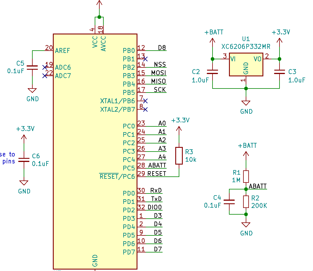
I'm using the internal 1.1v voltage reference of the atmega, so by my understanding I can't measure more than 1.1v on the analog inputs. The atmega & RFM69 board will be powered from 4v - 6v depending on the application, via a 3.3v regulator. Based on these values I've come to the conclusion that resistors of 1M ohm & 200k ohm will be the best bet. Theres also a circuit diagram below of how the circuit is wired. Is this the easiest way to measure the battery?
-
Looks good to me. Since you're using a voltage source > 5V and provide regulated 3.3V, using the internal 1.1V reference seems to be the easiest way. For 4 to 6V, you should expect a reading of ~620 to 930, which should be good enough to get an idea of the battery voltage
-
I'm currently in the process of designing a custom mysensors board to use with an RFM69 radio and an atmega328p, and I've come unstuck working out the values needed for the resistors for the voltage dividers. The MySensors page on batteries is unfortunately clear as mud on the matter.
I'm using the internal 1.1v voltage reference of the atmega, so by my understanding I can't measure more than 1.1v on the analog inputs. The atmega & RFM69 board will be powered from 4v - 6v depending on the application, via a 3.3v regulator. Based on these values I've come to the conclusion that resistors of 1M ohm & 200k ohm will be the best bet. Theres also a circuit diagram below of how the circuit is wired. Is this the easiest way to measure the battery?
Hello! It looks like you're interested in this conversation, but you don't have an account yet.
Getting fed up of having to scroll through the same posts each visit? When you register for an account, you'll always come back to exactly where you were before, and choose to be notified of new replies (either via email, or push notification). You'll also be able to save bookmarks and upvote posts to show your appreciation to other community members.
With your input, this post could be even better 💗
Register Login