RS485, no communication
-
Hi,
I already use mysensors with NRF24L01 and it works well.
I would like to use mysensors with RS485 nodes but I have communication problems
I'm using an Arduino Duemilanove (yes, it's old but it still works well), an Arduino Uno compatible board and 2 RS485 modules for testing.
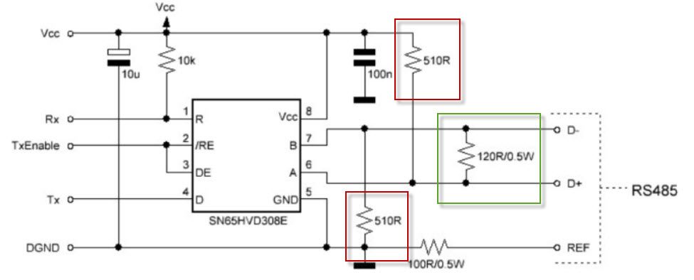
I used this wiring diagram: https://2.bp.blogspot.com/--MTeYYSu6nE/WViOqBi4T8I/AAAAAAAAUP8/cTphNMowJXUlAOn-oD44f1Wdd2NFrgpXgCLcBGAs/s1600/schemat%2BRS485%2BMySensors.jpg.I have exactly the same RS485 modules.
Here is the gateway code:
// Enable debug prints to serial monitor
#define MY_DEBUG

// Enable RS485 transport layer
#define MY_RS485

// Define this to enables DE-pin management on defined pin
#define MY_RS485_DE_PIN 2

// Set RS485 baud rate to use
#define MY_RS485_BAUD_RATE 9600

// Enable this if RS485 is connected to a hardware serial port
//#define MY_RS485_HWSERIAL Serial1

// Enable serial gateway
#define MY_GATEWAY_SERIAL


// Enable inclusion mode
#define MY_INCLUSION_MODE_FEATURE
// Enable Inclusion mode button on gateway
#define MY_INCLUSION_BUTTON_FEATURE
// Set inclusion mode duration (in seconds)
#define MY_INCLUSION_MODE_DURATION 60
// Digital pin used for inclusion mode button
#define MY_INCLUSION_MODE_BUTTON_PIN  3

// Set blinking period
#define MY_DEFAULT_LED_BLINK_PERIOD 300

// Flash leds on rx/tx/err
#define MY_DEFAULT_ERR_LED_PIN 4  // Error led pin
#define MY_DEFAULT_RX_LED_PIN  5  // Receive led pin
#define MY_DEFAULT_TX_LED_PIN  6  // the PCB, on board LED

#include <MySensors.h>

void setup()
{
	// Setup locally attached sensors
}

void presentation()
{
	// Present locally attached sensors
}

void loop()
{
	// Send locally attached sensor data here
}
And the gataway log:
Terminal ready
0;255;3;0;9;0 MCO:BGN:INIT GW,CP=RSNGA---,FQ=16,REL=255,VER=2.3.2
0;255;3;0;9;5 TSM:INIT
0;255;3;0;9;7 TSF:WUR:MS=0
0;255;3;0;9;10 TSM:INIT:TSP OK
0;255;3;0;9;13 TSM:INIT:GW MODE
0;255;3;0;9;15 TSM:READY:ID=0,PAR=0,DIS=0
0;255;3;0;9;19 MCO:REG:NOT NEEDED
0;255;3;0;14;Gateway startup complete.
0;255;0;0;18;2.3.2
0;255;3;0;9;23 MCO:BGN:STP
0;255;3;0;9;29 MCO:BGN:INIT OK,TSP=1
0;255;3;0;9;33 TSM:READY:NWD REQ
0;255;3;0;9;53 ?TSF:MSG:SEND,0-0-255-255,s=255,c=3,t=20,pt=0,l=0,sg=0,ft=0,st=OK:
And the node:
// Enable debug prints to serial monitor
#define MY_DEBUG

// Enable RS485 transport layer
#define MY_RS485

// Define this to enables DE-pin management on defined pin
#define MY_RS485_DE_PIN 2

// Set RS485 baud rate to use
#define MY_RS485_BAUD_RATE 9600

// Enable this if RS485 is connected to a hardware serial port
//#define MY_RS485_HWSERIAL Serial1

#define MY_NODE_ID 20

#include <MySensors.h>

static const uint64_t UPDATE_INTERVAL = 10000;

#define CHILD_ID_VALUE 0
MyMessage msgVal(CHILD_ID_VALUE, V_VAR1);

// ----------------------------------------------------------------------------
void presentation()
{
  // Send the sketch version information to the gateway
  sendSketchInfo("RS485 Node test Sensor", "1.0");

  // Register all sensors to gw (they will be created as child devices)
  present(CHILD_ID_VALUE, S_CUSTOM, "Node RS485");
}

// ----------------------------------------------------------------------------
void setup()
{
  Serial.println( F("Arduino MySensors RS485 Node test") );    // Fonction F() permet de placer la chaine dans la mémoire eprogramme (Arduino IDE 1.0).
  analogReference(INTERNAL);
  delay(1000);
}


void loop()
{
    Serial.println( F("Loop ...") );

    // Get millis
    long ms = millis();
    Serial.print(F("Millis: "));
    Serial.println(ms);
    send(msgVal.set(ms, 1));

    // Sleep for a while to save energy
    sleep(UPDATE_INTERVAL);
}
And the node log:
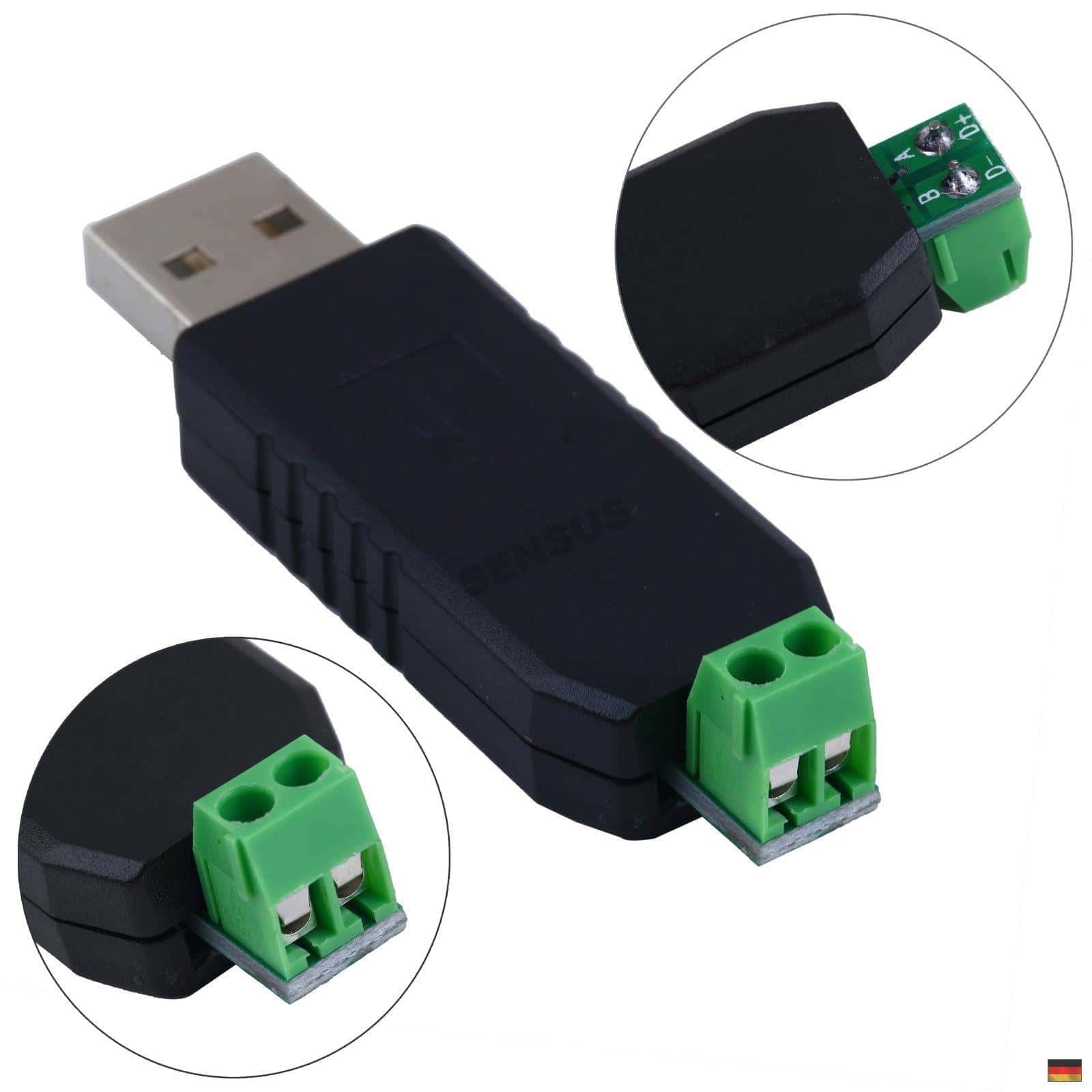
__  __       ____
|  \/  |_   _/ ___|  ___ _ __  ___  ___  _ __ ___
| |\/| | | | \___ \ / _ \ `_ \/ __|/ _ \| `__/ __|
| |  | | |_| |___| |  __/ | | \__ \  _  | |  \__ \
|_|  |_|\__, |____/ \___|_| |_|___/\___/|_|  |___/
       |___/                      2.3.2

16 MCO:BGN:INIT NODE,CP=RSNNA---,FQ=16,REL=255,VER=2.3.2
26 TSM:INIT
28 TSF:WUR:MS=0
29 TSM:INIT:TSP OK
31 TSM:FPAR
49 ?TSF:MSG:SEND,255-255-255-255,s=255,c=3,t=7,pt=0,l=0,sg=0,ft=0,st=OK:
2057 !TSM:FPAR:NO REPLY
2059 TSM:FPAR
2076 ?TSF:MSG:SEND,255-255-255-255,s=255,c=3,t=7,pt=0,l=0,sg=0,ft=0,st=OK:
4084 !TSM:FPAR:NO REPLY
4086 TSM:FPAR
4104 ?TSF:MSG:SEND,255-255-255-255,s=255,c=3,t=7,pt=0,l=0,sg=0,ft=0,st=OK:
6112 !TSM:FPAR:NO REPLY
6114 TSM:FPAR
6131 ?TSF:MSG:SEND,255-255-255-255,s=255,c=3,t=7,pt=0,l=0,sg=0,ft=0,st=OK:
8139 !TSM:FPAR:FAIL
8140 TSM:FAIL:CNT=1
8142 TSM:FAIL:DIS
8144 TSF:TDI:TSL
18146 TSM:FAIL:RE-INIT
18148 TSM:INIT
18149 TSM:INIT:TSP OK
18151 TSM:FPAR
18169 ?TSF:MSG:SEND,255-255-255-255,s=255,c=3,t=7,pt=0,l=0,sg=0,ft=0,st=OK:
20178 !TSM:FPAR:NO REPLY
20180 TSM:FPAR
20199 ?TSF:MSG:SEND,255-255-255-255,s=255,c=3,t=7,pt=0,l=0,sg=0,ft=0,st=OK:
22206 !TSM:FPAR:NO REPLY
22208 TSM:FPAR
To debug, I also use this USB RS485 module: https://www.makershop.de/wp-content/uploads/2016/01/1PC-font-b-USB-b-font-to-font-b-RS485-b-font-font-b-USB-b.jpg, this one is connected to the RS485 bus and I can see with a simple python program the data sent by the node:
01 ff 00 58 07 02 ff ff ff 02 03 07 ff 03 66 04
01 ff 00 58 07 02 ff ff ff 02 03 07 ff 03 66 04
01 ff 00 58 07 02 ff ff ff 02 03 07 ff 03 66 04
01 ff 00 58 07 02 ff ff ff 02 03 07 ff 03 66 04
...
Still nothing is received on the gateway !
I have checked the wiring several times, and tested with other identical RS485 modules but still the same problem.Would you have other tracks?
Thanks
ps: I use Arduino IDE 1.8.13 and MySensors lib 2.3.2
-
I found my problem
I added the parent node ID:#define MY_PARENT_NODE_ID 0in the node sketch and now it works
@vdomos this is very strange - it works for me without this directive..
#define MY_BAUD_RATE 9600 #define MY_NODE_ID 111 //#define MY_PARENT_NODE_ID 0 //#define MY_PARENT_NODE_IS_STATIC #define MY_DEBUG #define MY_OTA_FIRMWARE_FEATURE #define MY_OTA_FLASH_SS 16 // pin A2 of Arduino Pro Mini #define MY_OTA_FLASH_JDECID 0xEF30 #define MY_OTA_RETRY (10u) #define MY_OTA_RETRY_DELAY (2000u) #define MY_RS485 #define MY_RS485_DE_PIN 7 #define MY_RS485_BAUD_RATE 9600 #include <SPI.h> #include <MySensors.h> void setup() { pinMode(6, OUTPUT); } void before() { } void presentation() { sendSketchInfo("Test_RS485_OTA", "2.3.2.0.004"); } void loop() { digitalWrite(6,0); wait(100); digitalWrite(6,1); wait(100); digitalWrite(6,0); wait(100); digitalWrite(6,1); sendHeartbeat(); wait(5000); } -
@cabat , you are right
I commented on the MY_PARENT_NODE_ID line and after uploading sketch, I still receive on the gateway.
The problem was elsewhere but I don't understand where
-
@cabat , The Gnd is not needed, only the A and B pins are needed, I think.
I tested a 2nd node with the same sketch, only the "MY_NODE_ID" was changed.
It works perfectly without needing the "MY_PARENT_NODE_ID" directive.Both nodes are communicating well with the gateway now.
-
Hi,
I have the same issue.
I used example library and upload Serial Gateway RS485 and Motion Sensor RS485. Both to Arduino UNO. Wiring according to (https://forum.mysensors.org/assets/uploads/files/1585670689122-example-rs485-mqtt.p)
Gateway Log
0;255;3;0;9;0 MCO:BGN:INIT GW,CP=RSNGA---,FQ=16,REL=255,VER=2.3.2
0;255;3;0;9;5 TSM:INIT
0;255;3;0;9;7 TSF:WUR:MS=0
0;255;3;0;9;10 TSM:INIT:TSP OK
0;255;3;0;9;13 TSM:INIT:GW MODE
0;255;3;0;9;15 TSM:READY:ID=0,PAR=0,DIS=0
0;255;3;0;9;19 MCO:REG:NOT NEEDED
0;255;3;0;14;Gateway startup complete.
0;255;0;0;18;2.3.2
0;255;3;0;9;23 MCO:BGN:STP
0;255;3;0;9;29 MCO:BGN:INIT OK,TSP=1
0;255;3;0;9;33 TSM:READY:NWD REQ
0;255;3;0;9;53 ?TSF:MSG:SEND,0-0-255-255,s=255,c=3,t=20,pt=0,l=0,sg=0,ft=0,st=OK:
NOD Log
16 MCO:BGN:INIT NODE,CP=RSNNA---,FQ=16,REL=255,VER=2.3.2
26 TSM:INIT
28 TSF:WUR:MS=0
29 TSM:INIT:TSP OK
31 TSF:SID:OK,ID=123
32 TSM:FPAR
51 ?TSF:MSG:SEND,123-123-255-255,s=255,c=3,t=7,pt=0,l=0,sg=0,ft=0,st=OK:
2059 !TSM:FPAR:NO REPLY
2061 TSM:FPAR
2078 ?TSF:MSG:SEND,123-123-255-255,s=255,c=3,t=7,pt=0,l=0,sg=0,ft=0,st=OK:
4086 !TSM:FPAR:NO REPLY
4088 TSM:FPAR
4106 ?TSF:MSG:SEND,123-123-255-255,s=255,c=3,t=7,pt=0,l=0,sg=0,ft=0,st=OK:
6114 !TSM:FPAR:NO REPLY
6116 TSM:FPAR
6133 ?TSF:MSG:SEND,123-123-255-255,s=255,c=3,t=7,pt=0,l=0,sg=0,ft=0,st=OK:
8141 !TSM:FPAR:FAIL
8142 TSM:FAIL:CNT=1
8144 TSM:FAIL:DIS
8146 TSF:TDI:TSL
18148 TSM:FAIL:RE-INIT
18150 TSM:INIT
18151 TSM:INIT:TSP OK
18153 TSF:SID:OK,ID=123
18155 TSM:FPAR
18173 ?TSF:MSG:SEND,123-123-255-255,s=255,c=3,t=7,pt=0,l=0,sg=0,ft=0,st=OK:
20182 !TSM:FPAR:NO REPLY
Try with NODE ID definition or without
#define MY_PARENT_NODE_ID 0Thnak you for any help!!
-
hello, maybe a hardware issue
please checkRef https://forum.mysensors.org/topic/4854/building-a-wired-rs485-sensor-network/99
he 510 ohm pull up and pull down resistors are usually mounted on the master side. Theoretically it
would be best to install it in the middle of your bus line. The 120 ohm termination resistor must always
be used on distances greater than 1 meter and/or baud rates higher than 9600. It’s best to install it as a
norm as noise and reflections will cause havoc on your communication once implemented in the field.
The termination resistors should be mounted at both ends of the bus line. Please note that adding bias
resistors will load the driver IC output. With the indicated values the max number of units on the bus
line is limited to eight 12kΩ, sixteen 24kΩ, or thirty-two 48kΩ units.
For further protection transient suppressors can be installed across the differential lines, from the Vcc to
D+ and from GND to D-.!
Hello! It looks like you're interested in this conversation, but you don't have an account yet.
Getting fed up of having to scroll through the same posts each visit? When you register for an account, you'll always come back to exactly where you were before, and choose to be notified of new replies (either via email, or push notification). You'll also be able to save bookmarks and upvote posts to show your appreciation to other community members.
With your input, this post could be even better 💗
Register Login