Problems ethernet GW with ESP8266- NodeMcu V3.4
-
Trying to accomplish a ethernet GW with ESP8266 + RFM69.
Im using the GatewayESP8266-example. It compiles and downloads apparently ok, but it will not run. There is no output on the serial monitor (apart from the boot message on baudrate 74880) I tried all other available baudrates with no success/outputs.
23:33:01.222 ->  ets Jan  8 2013,rst cause:2, boot mode:(3,6)
23:33:01.222 ->
23:33:01.222 -> load 0x4010f000, len 3460, room 16
23:33:01.255 -> tail 4
23:33:01.255 -> chksum 0xcc
23:33:01.255 -> load 0x3fff20b8, len 40, room 4
23:33:01.255 -> tail 4
23:33:01.255 -> chksum 0xc9
23:33:01.255 -> csum 0xc9
23:33:01.255 -> v00047740
23:33:01.255 -> ~ld
Im using board library version 3.02 for the ESP8266 (selecting NodeMCU 1.0 (ESP-12E Module)). Latest version for Mysensors (2.3.2)
I tried to run the nodeMcu board stand alone and connected to the RFM69HCW, no difference.
As a test I have tried the arduino-included basic "blink", which works. I then added the blink-part to the GatewayESP8266-example => no flashing led.
Im using the NodeMCU v3.4 version 'Lolin'.
The instruction mentions specific wiring for "barebone" ESP8266 to switch between download/run code. Is my NodeMCU v3.4 barebone? I assume it does not need specific wiring as the blink-example is able to run?
Any help appreciated. Thanks!
@perIpI Something is causing your esp to reboot. To be able to help finding the cause, providing a wiring diagram and the sketch can help
reset causes:
The codes are :0 -> normal startup by power on 1 -> hardware watch dog reset 2 -> software watch dog reset (From an exception) 3 -> software watch dog reset system_restart (Possibly unfed watchdog got angry) 4 -> soft restart (Possibly with a restart command) 5 -> wake up from deep-sleepSo it's in the code, as you get a software reset caused by an exception
-
@perIpI Something is causing your esp to reboot. To be able to help finding the cause, providing a wiring diagram and the sketch can help
reset causes:
The codes are :0 -> normal startup by power on 1 -> hardware watch dog reset 2 -> software watch dog reset (From an exception) 3 -> software watch dog reset system_restart (Possibly unfed watchdog got angry) 4 -> soft restart (Possibly with a restart command) 5 -> wake up from deep-sleepSo it's in the code, as you get a software reset caused by an exception
@TheoL Thanks for you help!
I should add the "boot-message" only comes when i press the RST. I assumed that the "rst cause:2" was caused by me pressing reset? No continues reboot otherwise.
This is my wiring. I should add that I initially wired the RFM69-radio wrong (was not aware that the pinout was different for a RFM69HCW compared to a non H-version). I checked it with my fluke and all is correct connected, no shorts detected either.
I tested with the NodeMcu connected to radio but also with the NodeMCU only connected to usb (nothing else). Totally I have tested 3 nodeMcu:s. The basic "blink"-example will operate both in solo and with radio connected.
Im starting to think that the NodeMCU version "3.4" Link to desc. is different from the version 2 used in the mySensors-example. Maybe there is a compiler-setting that needs to be altered?
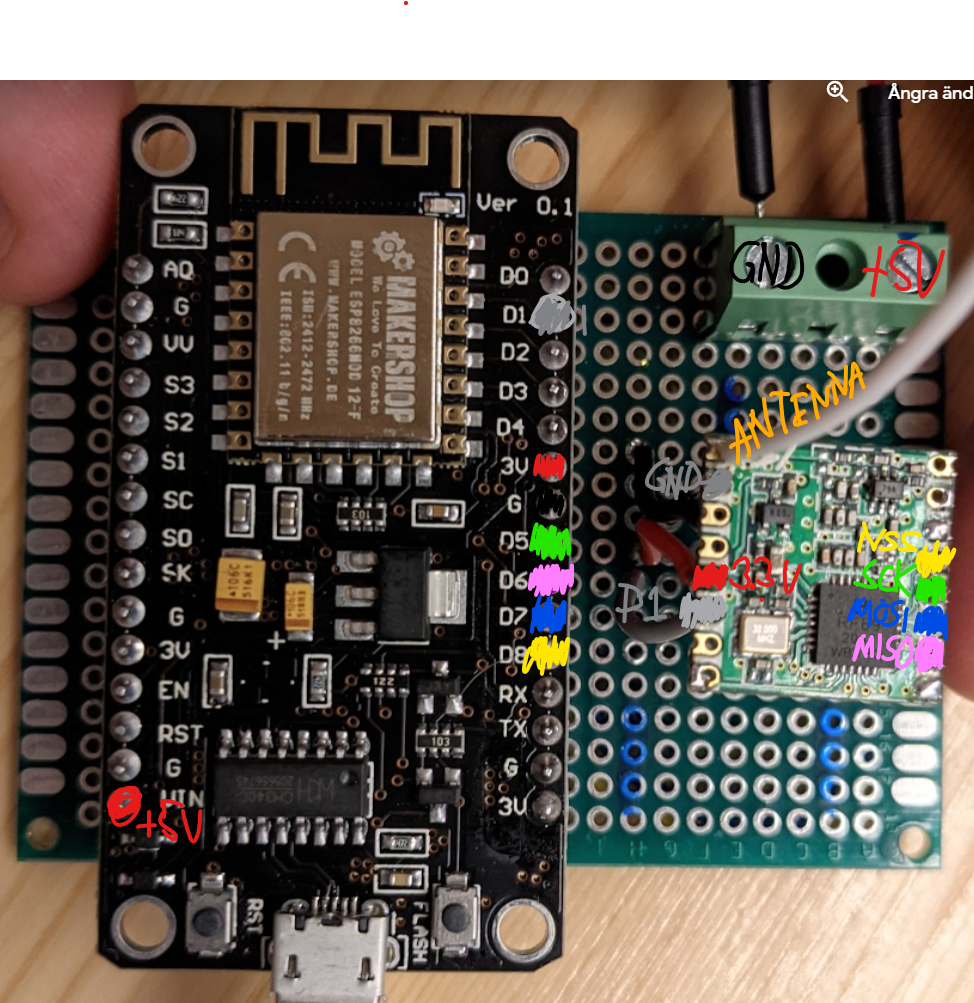
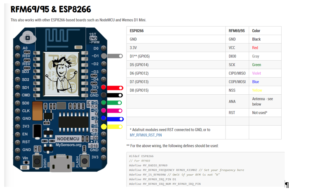
Wiring done after this guiding:
My code is as follows (ie just copy paste from the examples and editing the SSID and password)
/*
   The MySensors Arduino library handles the wireless radio link and protocol
   between your home built sensors/actuators and HA controller of choice.
   The sensors forms a self healing radio network with optional repeaters. Each
   repeater and gateway builds a routing tables in EEPROM which keeps track of the
   network topology allowing messages to be routed to nodes.

   Created by Henrik Ekblad <henrik.ekblad@mysensors.org>
   Copyright (C) 2013-2019 Sensnology AB
   Full contributor list: https://github.com/mysensors/MySensors/graphs/contributors

   Documentation: http://www.mysensors.org
   Support Forum: http://forum.mysensors.org

   This program is free software; you can redistribute it and/or
   modify it under the terms of the GNU General Public License
   version 2 as published by the Free Software Foundation.

 *******************************

   REVISION HISTORY
   Version 1.0 - Henrik Ekblad
   Contribution by a-lurker and Anticimex,
   Contribution by Norbert Truchsess <norbert.truchsess@t-online.de>
   Contribution by Ivo Pullens (ESP8266 support)

   DESCRIPTION
   The EthernetGateway sends data received from sensors to the WiFi link.
   The gateway also accepts input on ethernet interface, which is then sent out to the radio network.

   VERA CONFIGURATION:
   Enter "ip-number:port" in the ip-field of the Arduino GW device. This will temporarily override any serial configuration for the Vera plugin.
   E.g. If you want to use the default values in this sketch enter: 192.168.178.66:5003

   LED purposes:
   - To use the feature, uncomment any of the MY_DEFAULT_xx_LED_PINs in your sketch, only the LEDs that is defined is used.
   - RX (green) - blink fast on radio message received. In inclusion mode will blink fast only on presentation received
   - TX (yellow) - blink fast on radio message transmitted. In inclusion mode will blink slowly
   - ERR (red) - fast blink on error during transmission error or receive crc error

   See https://www.mysensors.org/build/connect_radio for wiring instructions.

   If you are using a "barebone" ESP8266, see
   https://www.mysensors.org/build/esp8266_gateway#wiring-for-barebone-esp8266

   Inclusion mode button:
   - Connect GPIO5 (=D1) via switch to GND ('inclusion switch')

   Hardware SHA204 signing is currently not supported!

   Make sure to fill in your ssid and WiFi password below for ssid & pass.
*/

// Enable debug prints to serial monitor
#define MY_DEBUG

// Use a bit lower baudrate for serial prints on ESP8266 than default in MyConfig.h
#define MY_BAUD_RATE 9600

// Enables and select radio type (if attached)
//#define MY_RADIO_RF24
#define MY_RADIO_RFM69 //Tried with and without commenting out RFM69
//#define MY_RADIO_RFM95
#define MY_RFM69_FREQUENCY RFM69_433MHZ // Set your frequency here
#define MY_IS_RFM69HW // Omit if your RFM is not "H"
#define MY_RFM69_IRQ_PIN D1
#define MY_RFM69_IRQ_NUM MY_RFM69_IRQ_PIN
#define MY_RFM69_CS_PIN D8 // NSS. Use MY_RFM69_SPI_CS for older versions (before 2.2.0)


#define MY_GATEWAY_ESP8266

#define MY_WIFI_SSID "xxxx"
#define MY_WIFI_PASSWORD "xxxxx"

// Enable UDP communication
//#define MY_USE_UDP  // If using UDP you need to set MY_CONTROLLER_IP_ADDRESS or MY_CONTROLLER_URL_ADDRESS below

// Set the hostname for the WiFi Client. This is the hostname
// it will pass to the DHCP server if not static.
#define MY_HOSTNAME "ESP8266_GW"

// Enable MY_IP_ADDRESS here if you want a static ip address (no DHCP)
//#define MY_IP_ADDRESS 192,168,178,87

// If using static ip you can define Gateway and Subnet address as well
//#define MY_IP_GATEWAY_ADDRESS 192,168,178,1
//#define MY_IP_SUBNET_ADDRESS 255,255,255,0

// The port to keep open on node server mode
#define MY_PORT 5003

// How many clients should be able to connect to this gateway (default 1)
#define MY_GATEWAY_MAX_CLIENTS 2

// Controller ip address. Enables client mode (default is "server" mode).
// Also enable this if MY_USE_UDP is used and you want sensor data sent somewhere.
//#define MY_CONTROLLER_IP_ADDRESS 192, 168, 178, 68
//#define MY_CONTROLLER_URL_ADDRESS "my.controller.org"

// Enable inclusion mode
//#define MY_INCLUSION_MODE_FEATURE

// Enable Inclusion mode button on gateway
//#define MY_INCLUSION_BUTTON_FEATURE
// Set inclusion mode duration (in seconds)
//#define MY_INCLUSION_MODE_DURATION 60
// Digital pin used for inclusion mode button
//#define MY_INCLUSION_MODE_BUTTON_PIN D1

// Set blinking period
//#define MY_DEFAULT_LED_BLINK_PERIOD 300

// Flash leds on rx/tx/err
// Led pins used if blinking feature is enabled above
//#define MY_DEFAULT_ERR_LED_PIN 16  // Error led pin
//#define MY_DEFAULT_RX_LED_PIN  16  // Receive led pin
//#define MY_DEFAULT_TX_LED_PIN  16  // the PCB, on board LED

#include <MySensors.h>

void setup() {
  // initialize digital pin LED_BUILTIN as an output.
  pinMode(LED_BUILTIN, OUTPUT);
}

// the loop function runs over and over again forever
void loop() {
  // Below is blink-example, tried with and without this code - ie empty loop() and setup()
  digitalWrite(LED_BUILTIN, HIGH);   // turn the LED on (HIGH is the voltage level)
  delay(1000);                       // wait for a second
  digitalWrite(LED_BUILTIN, LOW);    // turn the LED off by making the voltage LOW
  delay(1000);                       // wait for a second
}

void presentation()
{
  // Present locally attached sensors here
}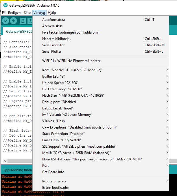
-
@TheoL Thanks for you help!
I should add the "boot-message" only comes when i press the RST. I assumed that the "rst cause:2" was caused by me pressing reset? No continues reboot otherwise.
This is my wiring. I should add that I initially wired the RFM69-radio wrong (was not aware that the pinout was different for a RFM69HCW compared to a non H-version). I checked it with my fluke and all is correct connected, no shorts detected either.
I tested with the NodeMcu connected to radio but also with the NodeMCU only connected to usb (nothing else). Totally I have tested 3 nodeMcu:s. The basic "blink"-example will operate both in solo and with radio connected.
Im starting to think that the NodeMCU version "3.4" Link to desc. is different from the version 2 used in the mySensors-example. Maybe there is a compiler-setting that needs to be altered?
Wiring done after this guiding:
My code is as follows (ie just copy paste from the examples and editing the SSID and password)
/* The MySensors Arduino library handles the wireless radio link and protocol between your home built sensors/actuators and HA controller of choice. The sensors forms a self healing radio network with optional repeaters. Each repeater and gateway builds a routing tables in EEPROM which keeps track of the network topology allowing messages to be routed to nodes. Created by Henrik Ekblad <henrik.ekblad@mysensors.org> Copyright (C) 2013-2019 Sensnology AB Full contributor list: https://github.com/mysensors/MySensors/graphs/contributors Documentation: http://www.mysensors.org Support Forum: http://forum.mysensors.org This program is free software; you can redistribute it and/or modify it under the terms of the GNU General Public License version 2 as published by the Free Software Foundation. ******************************* REVISION HISTORY Version 1.0 - Henrik Ekblad Contribution by a-lurker and Anticimex, Contribution by Norbert Truchsess <norbert.truchsess@t-online.de> Contribution by Ivo Pullens (ESP8266 support) DESCRIPTION The EthernetGateway sends data received from sensors to the WiFi link. The gateway also accepts input on ethernet interface, which is then sent out to the radio network. VERA CONFIGURATION: Enter "ip-number:port" in the ip-field of the Arduino GW device. This will temporarily override any serial configuration for the Vera plugin. E.g. If you want to use the default values in this sketch enter: 192.168.178.66:5003 LED purposes: - To use the feature, uncomment any of the MY_DEFAULT_xx_LED_PINs in your sketch, only the LEDs that is defined is used. - RX (green) - blink fast on radio message received. In inclusion mode will blink fast only on presentation received - TX (yellow) - blink fast on radio message transmitted. In inclusion mode will blink slowly - ERR (red) - fast blink on error during transmission error or receive crc error See https://www.mysensors.org/build/connect_radio for wiring instructions. If you are using a "barebone" ESP8266, see https://www.mysensors.org/build/esp8266_gateway#wiring-for-barebone-esp8266 Inclusion mode button: - Connect GPIO5 (=D1) via switch to GND ('inclusion switch') Hardware SHA204 signing is currently not supported! Make sure to fill in your ssid and WiFi password below for ssid & pass. */ // Enable debug prints to serial monitor #define MY_DEBUG // Use a bit lower baudrate for serial prints on ESP8266 than default in MyConfig.h #define MY_BAUD_RATE 9600 // Enables and select radio type (if attached) //#define MY_RADIO_RF24 #define MY_RADIO_RFM69 //Tried with and without commenting out RFM69 //#define MY_RADIO_RFM95 #define MY_RFM69_FREQUENCY RFM69_433MHZ // Set your frequency here #define MY_IS_RFM69HW // Omit if your RFM is not "H" #define MY_RFM69_IRQ_PIN D1 #define MY_RFM69_IRQ_NUM MY_RFM69_IRQ_PIN #define MY_RFM69_CS_PIN D8 // NSS. Use MY_RFM69_SPI_CS for older versions (before 2.2.0) #define MY_GATEWAY_ESP8266 #define MY_WIFI_SSID "xxxx" #define MY_WIFI_PASSWORD "xxxxx" // Enable UDP communication //#define MY_USE_UDP // If using UDP you need to set MY_CONTROLLER_IP_ADDRESS or MY_CONTROLLER_URL_ADDRESS below // Set the hostname for the WiFi Client. This is the hostname // it will pass to the DHCP server if not static. #define MY_HOSTNAME "ESP8266_GW" // Enable MY_IP_ADDRESS here if you want a static ip address (no DHCP) //#define MY_IP_ADDRESS 192,168,178,87 // If using static ip you can define Gateway and Subnet address as well //#define MY_IP_GATEWAY_ADDRESS 192,168,178,1 //#define MY_IP_SUBNET_ADDRESS 255,255,255,0 // The port to keep open on node server mode #define MY_PORT 5003 // How many clients should be able to connect to this gateway (default 1) #define MY_GATEWAY_MAX_CLIENTS 2 // Controller ip address. Enables client mode (default is "server" mode). // Also enable this if MY_USE_UDP is used and you want sensor data sent somewhere. //#define MY_CONTROLLER_IP_ADDRESS 192, 168, 178, 68 //#define MY_CONTROLLER_URL_ADDRESS "my.controller.org" // Enable inclusion mode //#define MY_INCLUSION_MODE_FEATURE // Enable Inclusion mode button on gateway //#define MY_INCLUSION_BUTTON_FEATURE // Set inclusion mode duration (in seconds) //#define MY_INCLUSION_MODE_DURATION 60 // Digital pin used for inclusion mode button //#define MY_INCLUSION_MODE_BUTTON_PIN D1 // Set blinking period //#define MY_DEFAULT_LED_BLINK_PERIOD 300 // Flash leds on rx/tx/err // Led pins used if blinking feature is enabled above //#define MY_DEFAULT_ERR_LED_PIN 16 // Error led pin //#define MY_DEFAULT_RX_LED_PIN 16 // Receive led pin //#define MY_DEFAULT_TX_LED_PIN 16 // the PCB, on board LED #include <MySensors.h> void setup() { // initialize digital pin LED_BUILTIN as an output. pinMode(LED_BUILTIN, OUTPUT); } // the loop function runs over and over again forever void loop() { // Below is blink-example, tried with and without this code - ie empty loop() and setup() digitalWrite(LED_BUILTIN, HIGH); // turn the LED on (HIGH is the voltage level) delay(1000); // wait for a second digitalWrite(LED_BUILTIN, LOW); // turn the LED off by making the voltage LOW delay(1000); // wait for a second } void presentation() { // Present locally attached sensors here }@perIpI I don't know if this will be helpful - I haven't used an ESP8266 on MySensors, nor have I really messed with one hardly at all.
But when I was troubleshooting my NRF51822 with MySensors, I was surprised that there were two different baud rates. I had MY_DEBUG enabled, and during the library initialization and waiting for the controller to hand out an ID it had one speed, while during normal use it had another. (I had other issues, so this took a while to resolve.) I also had Serial.begin(9600) but during startup it ran at 115200. Once it got to my code it then switched to 9600 and ran the rest of the time at that speed.
So all of that is to say that it's possible that if you let it run until you stop seeing responses at the faster 74880 speed, you might then get some results by switching and watching it at 9600. (Of course if you've already tried that then this won't help.)
Alternatively, you could simply switch the speed in your code to match the 74880 speed that you're seeing results at, and maybe you'll then see everything in the same window.
-
@TheoL Thanks for you help!
I should add the "boot-message" only comes when i press the RST. I assumed that the "rst cause:2" was caused by me pressing reset? No continues reboot otherwise.
This is my wiring. I should add that I initially wired the RFM69-radio wrong (was not aware that the pinout was different for a RFM69HCW compared to a non H-version). I checked it with my fluke and all is correct connected, no shorts detected either.
I tested with the NodeMcu connected to radio but also with the NodeMCU only connected to usb (nothing else). Totally I have tested 3 nodeMcu:s. The basic "blink"-example will operate both in solo and with radio connected.
Im starting to think that the NodeMCU version "3.4" Link to desc. is different from the version 2 used in the mySensors-example. Maybe there is a compiler-setting that needs to be altered?
Wiring done after this guiding:
My code is as follows (ie just copy paste from the examples and editing the SSID and password)
/* The MySensors Arduino library handles the wireless radio link and protocol between your home built sensors/actuators and HA controller of choice. The sensors forms a self healing radio network with optional repeaters. Each repeater and gateway builds a routing tables in EEPROM which keeps track of the network topology allowing messages to be routed to nodes. Created by Henrik Ekblad <henrik.ekblad@mysensors.org> Copyright (C) 2013-2019 Sensnology AB Full contributor list: https://github.com/mysensors/MySensors/graphs/contributors Documentation: http://www.mysensors.org Support Forum: http://forum.mysensors.org This program is free software; you can redistribute it and/or modify it under the terms of the GNU General Public License version 2 as published by the Free Software Foundation. ******************************* REVISION HISTORY Version 1.0 - Henrik Ekblad Contribution by a-lurker and Anticimex, Contribution by Norbert Truchsess <norbert.truchsess@t-online.de> Contribution by Ivo Pullens (ESP8266 support) DESCRIPTION The EthernetGateway sends data received from sensors to the WiFi link. The gateway also accepts input on ethernet interface, which is then sent out to the radio network. VERA CONFIGURATION: Enter "ip-number:port" in the ip-field of the Arduino GW device. This will temporarily override any serial configuration for the Vera plugin. E.g. If you want to use the default values in this sketch enter: 192.168.178.66:5003 LED purposes: - To use the feature, uncomment any of the MY_DEFAULT_xx_LED_PINs in your sketch, only the LEDs that is defined is used. - RX (green) - blink fast on radio message received. In inclusion mode will blink fast only on presentation received - TX (yellow) - blink fast on radio message transmitted. In inclusion mode will blink slowly - ERR (red) - fast blink on error during transmission error or receive crc error See https://www.mysensors.org/build/connect_radio for wiring instructions. If you are using a "barebone" ESP8266, see https://www.mysensors.org/build/esp8266_gateway#wiring-for-barebone-esp8266 Inclusion mode button: - Connect GPIO5 (=D1) via switch to GND ('inclusion switch') Hardware SHA204 signing is currently not supported! Make sure to fill in your ssid and WiFi password below for ssid & pass. */ // Enable debug prints to serial monitor #define MY_DEBUG // Use a bit lower baudrate for serial prints on ESP8266 than default in MyConfig.h #define MY_BAUD_RATE 9600 // Enables and select radio type (if attached) //#define MY_RADIO_RF24 #define MY_RADIO_RFM69 //Tried with and without commenting out RFM69 //#define MY_RADIO_RFM95 #define MY_RFM69_FREQUENCY RFM69_433MHZ // Set your frequency here #define MY_IS_RFM69HW // Omit if your RFM is not "H" #define MY_RFM69_IRQ_PIN D1 #define MY_RFM69_IRQ_NUM MY_RFM69_IRQ_PIN #define MY_RFM69_CS_PIN D8 // NSS. Use MY_RFM69_SPI_CS for older versions (before 2.2.0) #define MY_GATEWAY_ESP8266 #define MY_WIFI_SSID "xxxx" #define MY_WIFI_PASSWORD "xxxxx" // Enable UDP communication //#define MY_USE_UDP // If using UDP you need to set MY_CONTROLLER_IP_ADDRESS or MY_CONTROLLER_URL_ADDRESS below // Set the hostname for the WiFi Client. This is the hostname // it will pass to the DHCP server if not static. #define MY_HOSTNAME "ESP8266_GW" // Enable MY_IP_ADDRESS here if you want a static ip address (no DHCP) //#define MY_IP_ADDRESS 192,168,178,87 // If using static ip you can define Gateway and Subnet address as well //#define MY_IP_GATEWAY_ADDRESS 192,168,178,1 //#define MY_IP_SUBNET_ADDRESS 255,255,255,0 // The port to keep open on node server mode #define MY_PORT 5003 // How many clients should be able to connect to this gateway (default 1) #define MY_GATEWAY_MAX_CLIENTS 2 // Controller ip address. Enables client mode (default is "server" mode). // Also enable this if MY_USE_UDP is used and you want sensor data sent somewhere. //#define MY_CONTROLLER_IP_ADDRESS 192, 168, 178, 68 //#define MY_CONTROLLER_URL_ADDRESS "my.controller.org" // Enable inclusion mode //#define MY_INCLUSION_MODE_FEATURE // Enable Inclusion mode button on gateway //#define MY_INCLUSION_BUTTON_FEATURE // Set inclusion mode duration (in seconds) //#define MY_INCLUSION_MODE_DURATION 60 // Digital pin used for inclusion mode button //#define MY_INCLUSION_MODE_BUTTON_PIN D1 // Set blinking period //#define MY_DEFAULT_LED_BLINK_PERIOD 300 // Flash leds on rx/tx/err // Led pins used if blinking feature is enabled above //#define MY_DEFAULT_ERR_LED_PIN 16 // Error led pin //#define MY_DEFAULT_RX_LED_PIN 16 // Receive led pin //#define MY_DEFAULT_TX_LED_PIN 16 // the PCB, on board LED #include <MySensors.h> void setup() { // initialize digital pin LED_BUILTIN as an output. pinMode(LED_BUILTIN, OUTPUT); } // the loop function runs over and over again forever void loop() { // Below is blink-example, tried with and without this code - ie empty loop() and setup() digitalWrite(LED_BUILTIN, HIGH); // turn the LED on (HIGH is the voltage level) delay(1000); // wait for a second digitalWrite(LED_BUILTIN, LOW); // turn the LED off by making the voltage LOW delay(1000); // wait for a second } void presentation() { // Present locally attached sensors here } -
I have exactly the same problem with the ESP8266 MQTT GW. It compiles and loads but there is nothing on the serial output. The ESP does not appear on the WiFi either. I have run other sketches like the NTP-server and the Blink sketch with exactly the same settings for the compiler. There is no difference if the radio is connected or not. My wiring is very simple, nothing connected except the micro-USB.
The suggestion by @peripi makes no difference. The bootload message comes at 74880 speed. Shifting to 9600 or setting any other speed for that matter makes no difference.Since I have compiled and run this same sketch earlier, I suspect there have been some breaking changes in the library version 3.0.2 or possibly elsewhere.
I post my code below but I think it is identical to the reference sketches on MySensors.
/**
 * The MySensors Arduino library handles the wireless radio link and protocol
 * between your home built sensors/actuators and HA controller of choice.
 * The sensors forms a self healing radio network with optional repeaters. Each
 * repeater and gateway builds a routing tables in EEPROM which keeps track of the
 * network topology allowing messages to be routed to nodes.
 *
 * Created by Henrik Ekblad <henrik.ekblad@mysensors.org>
 * Copyright (C) 2013-2015 Sensnology AB
 * Full contributor list: https://github.com/mysensors/Arduino/graphs/contributors
 *
 * Documentation: http://www.mysensors.org
 * Support Forum: http://forum.mysensors.org
 *
 * This program is free software; you can redistribute it and/or
 * modify it under the terms of the GNU General Public License
 * version 2 as published by the Free Software Foundation.
 *
 *******************************
 *
 * REVISION HISTORY
 * Version 1.0 - Henrik Ekblad
 * Version 1.1 - Gunnar Blockmar 2019-05-19 Configuration for Sjövik WLAN
 *
 * DESCRIPTION
 * The ESP8266 MQTT gateway sends radio network (or locally attached sensors) data to your MQTT broker.
 * The node also listens to MY_MQTT_TOPIC_PREFIX and sends out those messages to the radio network
 *
 * LED purposes:
 * - To use the feature, uncomment WITH_LEDS_BLINKING in MyConfig.h
 * - RX (green) - blink fast on radio message recieved. In inclusion mode will blink fast only on presentation recieved
 * - TX (yellow) - blink fast on radio message transmitted. In inclusion mode will blink slowly
 * - ERR (red) - fast blink on error during transmission error or recieve crc error
 *
 * See http://www.mysensors.org/build/esp8266_gateway for wiring instructions.
 * nRF24L01+  ESP8266
 * VCC        VCC
 * CE         GPIO4
 * CSN/CS     GPIO15
 * SCK        GPIO14
 * MISO       GPIO12
 * MOSI       GPIO13
 *
 * Not all ESP8266 modules have all pins available on their external interface.
 * This code has been tested on an ESP-12 module.
 * The ESP8266 requires a certain pin configuration to download code, and another one to run code:
 * - Connect REST (reset) via 10K pullup resistor to VCC, and via switch to GND ('reset switch')
 * - Connect GPIO15 via 10K pulldown resistor to GND
 * - Connect CH_PD via 10K resistor to VCC
 * - Connect GPIO2 via 10K resistor to VCC
 * - Connect GPIO0 via 10K resistor to VCC, and via switch to GND ('bootload switch')
 *
  * Inclusion mode button:
 * - Connect GPIO5 via switch to GND ('inclusion switch')
 *
 * Hardware SHA204 signing is currently not supported!
 *
 * Make sure to fill in your ssid and WiFi password below for ssid & pass.
 */

#include <EEPROM.h>
#include <SPI.h>

// Enable debug prints to serial monitor
#define MY_DEBUG

// Use a bit lower baudrate for serial prints on ESP8266 than default in MyConfig.h
#define MY_BAUD_RATE 9600

// Enables and select radio type (if attached)
#define MY_RADIO_RF24
//#define MY_RADIO_RFM69

#define MY_GATEWAY_MQTT_CLIENT
#define MY_GATEWAY_ESP8266

// Set this nodes subscripe and publish topic prefix
#define MY_MQTT_PUBLISH_TOPIC_PREFIX "prefix-out"
#define MY_MQTT_SUBSCRIBE_TOPIC_PREFIX "prefix-in"

// Set MQTT client id
#define MY_MQTT_CLIENT_ID "sensors"

// Enable these if your MQTT broker requires usenrame/password
#define MY_MQTT_USER "hidden"
#define MY_MQTT_PASSWORD "xyz123"

// Set WIFI SSID and password
#define MY_WIFI_SSID "secret"  // Change this at deployment
#define MY_WIFI_PASSWORD "secret"   //Change this at deployment

// Set the hostname for the WiFi Client. This is the hostname
// it will pass to the DHCP server if not static.
#define MY_HOSTNAME "test-gateway"

// Enable MY_IP_ADDRESS here if you want a static ip address (no DHCP)
//#define MY_IP_ADDRESS 192,168,178,87

// If using static ip you need to define Gateway and Subnet address as well
//#define MY_IP_GATEWAY_ADDRESS 192,168,178,1
//#define MY_IP_SUBNET_ADDRESS 255,255,255,0


// MQTT broker ip address.
//#define MY_CONTROLLER_IP_ADDRESS 192, 168, 178, 68
#define MY_CONTROLLER_URL_ADDRESS "xxx.cloudmqtt.com"


// The MQTT broker port to to open
#define MY_PORT 12345


// Flash leds on rx/tx/err does not work on ESP8266 no free pins
// #define MY_LEDS_BLINKING_FEATURE
// Set blinking period
// #define MY_DEFAULT_LED_BLINK_PERIOD 300
// Enable inclusion mode
// #define MY_INCLUSION_MODE_FEATURE
// Enable Inclusion mode button on gateway
// #define MY_INCLUSION_BUTTON_FEATURE
// Set inclusion mode duration (in seconds)
// #define MY_INCLUSION_MODE_DURATION 60
// Digital pin used for inclusion mode button
// #define MY_INCLUSION_MODE_BUTTON_PIN  3
// #define MY_DEFAULT_ERR_LED_PIN 1  // Error led pin
// #define MY_DEFAULT_RX_LED_PIN  9  // Receive led pin
// #define MY_DEFAULT_TX_LED_PIN  0  // Transmit led pin


#include <ESP8266WiFi.h>
#include <MySensors.h>

void setup() {

}

void presentation() {
  // Present locally attached sensors here
}


void loop() {
  // Send locally attached sensors data here
}
So at the end of my wits.
-
I have exactly the same problem with the ESP8266 MQTT GW. It compiles and loads but there is nothing on the serial output. The ESP does not appear on the WiFi either. I have run other sketches like the NTP-server and the Blink sketch with exactly the same settings for the compiler. There is no difference if the radio is connected or not. My wiring is very simple, nothing connected except the micro-USB.
The suggestion by @peripi makes no difference. The bootload message comes at 74880 speed. Shifting to 9600 or setting any other speed for that matter makes no difference.Since I have compiled and run this same sketch earlier, I suspect there have been some breaking changes in the library version 3.0.2 or possibly elsewhere.
I post my code below but I think it is identical to the reference sketches on MySensors.
/**
 * The MySensors Arduino library handles the wireless radio link and protocol
 * between your home built sensors/actuators and HA controller of choice.
 * The sensors forms a self healing radio network with optional repeaters. Each
 * repeater and gateway builds a routing tables in EEPROM which keeps track of the
 * network topology allowing messages to be routed to nodes.
 *
 * Created by Henrik Ekblad <henrik.ekblad@mysensors.org>
 * Copyright (C) 2013-2015 Sensnology AB
 * Full contributor list: https://github.com/mysensors/Arduino/graphs/contributors
 *
 * Documentation: http://www.mysensors.org
 * Support Forum: http://forum.mysensors.org
 *
 * This program is free software; you can redistribute it and/or
 * modify it under the terms of the GNU General Public License
 * version 2 as published by the Free Software Foundation.
 *
 *******************************
 *
 * REVISION HISTORY
 * Version 1.0 - Henrik Ekblad
 * Version 1.1 - Gunnar Blockmar 2019-05-19 Configuration for Sjövik WLAN
 *
 * DESCRIPTION
 * The ESP8266 MQTT gateway sends radio network (or locally attached sensors) data to your MQTT broker.
 * The node also listens to MY_MQTT_TOPIC_PREFIX and sends out those messages to the radio network
 *
 * LED purposes:
 * - To use the feature, uncomment WITH_LEDS_BLINKING in MyConfig.h
 * - RX (green) - blink fast on radio message recieved. In inclusion mode will blink fast only on presentation recieved
 * - TX (yellow) - blink fast on radio message transmitted. In inclusion mode will blink slowly
 * - ERR (red) - fast blink on error during transmission error or recieve crc error
 *
 * See http://www.mysensors.org/build/esp8266_gateway for wiring instructions.
 * nRF24L01+  ESP8266
 * VCC        VCC
 * CE         GPIO4
 * CSN/CS     GPIO15
 * SCK        GPIO14
 * MISO       GPIO12
 * MOSI       GPIO13
 *
 * Not all ESP8266 modules have all pins available on their external interface.
 * This code has been tested on an ESP-12 module.
 * The ESP8266 requires a certain pin configuration to download code, and another one to run code:
 * - Connect REST (reset) via 10K pullup resistor to VCC, and via switch to GND ('reset switch')
 * - Connect GPIO15 via 10K pulldown resistor to GND
 * - Connect CH_PD via 10K resistor to VCC
 * - Connect GPIO2 via 10K resistor to VCC
 * - Connect GPIO0 via 10K resistor to VCC, and via switch to GND ('bootload switch')
 *
  * Inclusion mode button:
 * - Connect GPIO5 via switch to GND ('inclusion switch')
 *
 * Hardware SHA204 signing is currently not supported!
 *
 * Make sure to fill in your ssid and WiFi password below for ssid & pass.
 */

#include <EEPROM.h>
#include <SPI.h>

// Enable debug prints to serial monitor
#define MY_DEBUG

// Use a bit lower baudrate for serial prints on ESP8266 than default in MyConfig.h
#define MY_BAUD_RATE 9600

// Enables and select radio type (if attached)
#define MY_RADIO_RF24
//#define MY_RADIO_RFM69

#define MY_GATEWAY_MQTT_CLIENT
#define MY_GATEWAY_ESP8266

// Set this nodes subscripe and publish topic prefix
#define MY_MQTT_PUBLISH_TOPIC_PREFIX "prefix-out"
#define MY_MQTT_SUBSCRIBE_TOPIC_PREFIX "prefix-in"

// Set MQTT client id
#define MY_MQTT_CLIENT_ID "sensors"

// Enable these if your MQTT broker requires usenrame/password
#define MY_MQTT_USER "hidden"
#define MY_MQTT_PASSWORD "xyz123"

// Set WIFI SSID and password
#define MY_WIFI_SSID "secret"  // Change this at deployment
#define MY_WIFI_PASSWORD "secret"   //Change this at deployment

// Set the hostname for the WiFi Client. This is the hostname
// it will pass to the DHCP server if not static.
#define MY_HOSTNAME "test-gateway"

// Enable MY_IP_ADDRESS here if you want a static ip address (no DHCP)
//#define MY_IP_ADDRESS 192,168,178,87

// If using static ip you need to define Gateway and Subnet address as well
//#define MY_IP_GATEWAY_ADDRESS 192,168,178,1
//#define MY_IP_SUBNET_ADDRESS 255,255,255,0


// MQTT broker ip address.
//#define MY_CONTROLLER_IP_ADDRESS 192, 168, 178, 68
#define MY_CONTROLLER_URL_ADDRESS "xxx.cloudmqtt.com"


// The MQTT broker port to to open
#define MY_PORT 12345


// Flash leds on rx/tx/err does not work on ESP8266 no free pins
// #define MY_LEDS_BLINKING_FEATURE
// Set blinking period
// #define MY_DEFAULT_LED_BLINK_PERIOD 300
// Enable inclusion mode
// #define MY_INCLUSION_MODE_FEATURE
// Enable Inclusion mode button on gateway
// #define MY_INCLUSION_BUTTON_FEATURE
// Set inclusion mode duration (in seconds)
// #define MY_INCLUSION_MODE_DURATION 60
// Digital pin used for inclusion mode button
// #define MY_INCLUSION_MODE_BUTTON_PIN  3
// #define MY_DEFAULT_ERR_LED_PIN 1  // Error led pin
// #define MY_DEFAULT_RX_LED_PIN  9  // Receive led pin
// #define MY_DEFAULT_TX_LED_PIN  0  // Transmit led pin


#include <ESP8266WiFi.h>
#include <MySensors.h>

void setup() {

}

void presentation() {
  // Present locally attached sensors here
}


void loop() {
  // Send locally attached sensors data here
}
So at the end of my wits.
To report back, no progress here either. I've tried to comment out the radio-definition part of the code, and also to move the IRQ-pin between D1 to D4. The nodeMCU will not run and there is no serial output other than the 74880 bootload-message.
I have ordered some NodeMCU version 2 (the ones Ive tried are version 3.4) units as well, but would be surprised if they would be any different.
Is it possible to edit mysensors.h somewhere and enable debugging at some positions just to get a clue of whats going on? I figure whats stopping the boot-up probably happens prior to the normal debugging messages.
An alternative approach could be to go backwards through the library versions (ESP8266 and mysensors) to try and find a working combination?
-
To report back, no progress here either. I've tried to comment out the radio-definition part of the code, and also to move the IRQ-pin between D1 to D4. The nodeMCU will not run and there is no serial output other than the 74880 bootload-message.
I have ordered some NodeMCU version 2 (the ones Ive tried are version 3.4) units as well, but would be surprised if they would be any different.
Is it possible to edit mysensors.h somewhere and enable debugging at some positions just to get a clue of whats going on? I figure whats stopping the boot-up probably happens prior to the normal debugging messages.
An alternative approach could be to go backwards through the library versions (ESP8266 and mysensors) to try and find a working combination?
@perIpI I know for sure d3 and d4 can give troubles with interrupts. As it can prevent the ESP from being booted.
I recently created a Wemos Mini d1 node. That works without any problems. But I use NRF24L01.
What happens when you comment out #include <MySensors.h> ?? I assume it would run. But use Serial.begin( 115200); and Serial.println( "Test" ); in the setup
Maybe someone like @Yveaux can help
-
I also edited according to @Yveaux 's workaround and it works!
I found however that in order to get the MQTT GW to listen to messages and forward them to the broker, I had to set wait(2000); in the void loop()
If I set wait(0) the GW started but did not listen to messages. If I set wait(100); the GW started spamming the broker with the presentation message.Again, a big thank you to everybody involved. "Now we are cooking with gas again!"
Hello! It looks like you're interested in this conversation, but you don't have an account yet.
Getting fed up of having to scroll through the same posts each visit? When you register for an account, you'll always come back to exactly where you were before, and choose to be notified of new replies (either via email, or push notification). You'll also be able to save bookmarks and upvote posts to show your appreciation to other community members.
With your input, this post could be even better 💗
Register Login