💬 Easy/Newbie PCB for MySensors
-
@gohan - interesting. What would be the easiest way to do this do you think? Placement?
Can I avoid SMD components? -
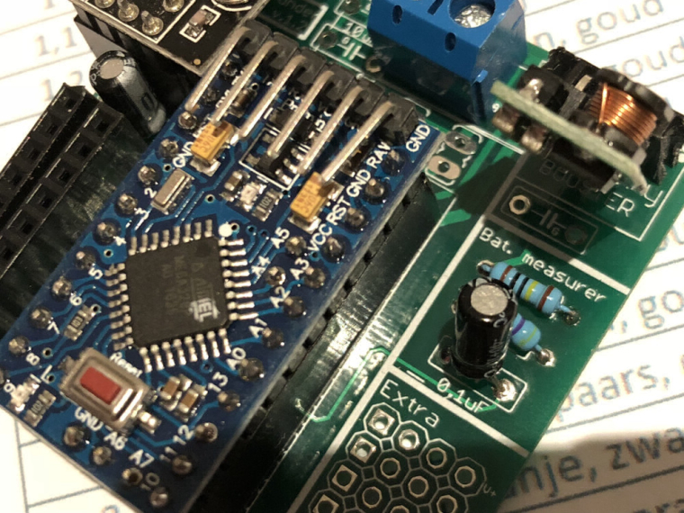
Put the battery measurement components under the Arduino. This makes the board more generic and frees up space on the right side of the board that can be used for more sensors. Expand the prototype area so that more sensors can be installed on the board.
And if one uses the board for battery only, the whole right section can be cut off but the battery measurement circuit is still there. -
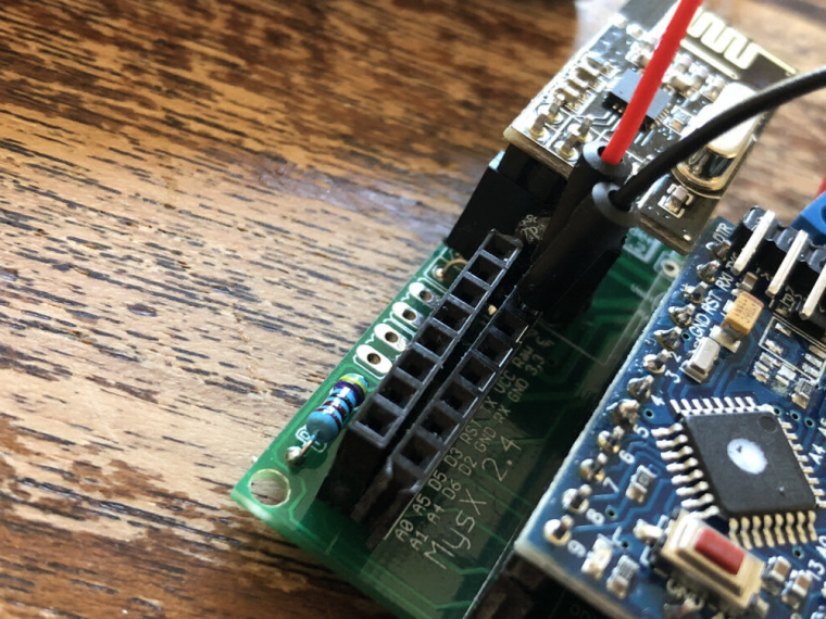
Now that I think of it, there is a small difference between the NRF and RFM board, the prototype area on the RFM board is not correctly spaced, the holes are a fraction to narrow spaced, one cant fit a header there without bending the pins
-
Now that I think of it, there is a small difference between the NRF and RFM board, the prototype area on the RFM board is not correctly spaced, the holes are a fraction to narrow spaced, one cant fit a header there without bending the pins
@mickecarlsson said in 💬 Easy/Newbie PCB for MySensors:
Now that I think of it, there is a small difference between the NRF and RFM board, the prototype area on the RFM board is not correctly spaced, the holes are a fraction to narrow spaced, one cant fit a header there without bending the pins
Yes, I noticed that too
-
@mickecarlsson said in 💬 Easy/Newbie PCB for MySensors:
Now that I think of it, there is a small difference between the NRF and RFM board, the prototype area on the RFM board is not correctly spaced, the holes are a fraction to narrow spaced, one cant fit a header there without bending the pins
Yes, I noticed that too
@gohan @mickecarlsson
Thanks for your input! I will probably redo the Nrf version in KiCad since the old in is in eagle so I will line everything up :)About the battery measurement components under the Arduino - I was thinking of putting the signing chip there.
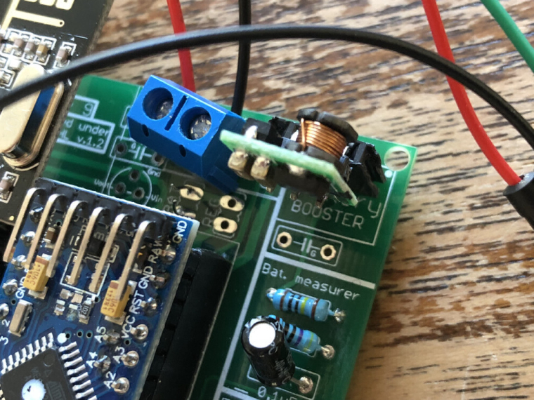
If you want to use the battery divider you need the booster as well so therefore its nessecary to have the board uncut. with this in mind I think it does not matter about the voltage divider placement or?Im not sure a 8 pin SMD component is right for EasyPCB - It seems a bit to advanced and unclear?
Maybe I can do this with a MysX shield? -
If I don’t use the booster and connect both BAT and REG and feed the board with two AA batteries i can use the battery components to measure the voltage of the battery. That is how I use it today.
-
If I don’t use the booster and connect both BAT and REG and feed the board with two AA batteries i can use the battery components to measure the voltage of the battery. That is how I use it today.
@mickecarlsson - ahh, I see - good one!
Let me think and maybe try some in KiCad and i let you know what I descide. -
The flash chip uses pins that are not on the connector.
I understand that you want to keep it simple, but adding the signing chip and the flash chip to a project it is not very easy either@gohan - you are right.
Maybe I can use the back side for the smd parts? Again I will test and see how it works out in KiCad. I might do some testing and post to get feedback. Im really afraid I will lose the easy to use function which the pcb is designed for though and if I feel I do the smd parts will be excluded.Maybe I could do a rev 10 which includes more heavy stuff and keep rev 9 as well as the Easy version.
-
I don't see it as a complicated thing, since if you don't need it then you just don't use it and you only have a few smd pads unused.
@gohan - valid point!
What makes it complicated is if you are a new user who sees all these pads and dont understand if they have to be populated or used. But by adding those with clear labels on the bottom side might do the trick.Controller: Proxmox VM - Home Assistant
MySensors GW: Arduino Uno - W5100 Ethernet, Gw Shield Nrf24l01+ 2,4Ghz
MySensors GW: Arduino Uno - Gw Shield RFM69, 433mhz
RFLink GW - Arduino Mega + RFLink Shield, 433mhz -
@gohan - valid point!
What makes it complicated is if you are a new user who sees all these pads and dont understand if they have to be populated or used. But by adding those with clear labels on the bottom side might do the trick. -
If I don’t use the booster and connect both BAT and REG and feed the board with two AA batteries i can use the battery components to measure the voltage of the battery. That is how I use it today.
@mickecarlsson said in 💬 Easy/Newbie PCB for MySensors:
If I don’t use the booster and connect both BAT and REG and feed the board with two AA batteries i can use the battery components to measure the voltage of the battery. That is how I use it today.
Why dont you use the internal library to measure the battery voltage? Im thinking about this and can't find a reason to move the voltage divider since without the booster you could just use the internalref and a library to measure the voltage?
-
@mickecarlsson said in 💬 Easy/Newbie PCB for MySensors:
If I don’t use the booster and connect both BAT and REG and feed the board with two AA batteries i can use the battery components to measure the voltage of the battery. That is how I use it today.
Why dont you use the internal library to measure the battery voltage? Im thinking about this and can't find a reason to move the voltage divider since without the booster you could just use the internalref and a library to measure the voltage?
@sundberg84 said in 💬 Easy/Newbie PCB for MySensors:
Why dont you use the internal library to measure the battery voltage? Im thinking about this and can't find a reason to move the voltage divider since without the booster you could just use the internalref and a library to measure the voltage?
Good point, I have not thought of that. I will test it it. And will probably save some uA in the process. Thanks,
-
@sundberg84 I have now a node running with the BAT link removed, the REG link attached and I have used the Arduino_Vcc library.
The battery report are consistent with the battery voltage measured with a digital volt meter.
EDIT: Code below had a bug in it, I have fixed the bug and updated the code. The bug affected the temperature readings
So, to run the RFM69 board on two AA batteries I have done the following:- Removed regulator and led from Arduino
- Burned a new bootloader with a 1.7 volt BOD
- Put a link in REG position
- Solder radio to board
- Solder antenna to board.
- Solder BME280 to power and A5, A6
And that's it.
Here is my code:
/** * The MySensors Arduino library handles the wireless radio link and protocol * between your home built sensors/actuators and HA controller of choice. * The sensors forms a self healing radio network with optional repeaters. Each * repeater and gateway builds a routing tables in EEPROM which keeps track of the * network topology allowing messages to be routed to nodes. * * Created by Henrik Ekblad <henrik.ekblad@mysensors.org> * Copyright (C) 2013-2015 Sensnology AB * Full contributor list: https://github.com/mysensors/Arduino/graphs/contributors * * Documentation: http://www.mysensors.org * Support Forum: http://forum.mysensors.org * * This program is free software; you can redistribute it and/or * modify it under the terms of the GNU General Public License * version 2 as published by the Free Software Foundation. * ******************************* * * DESCRIPTION * * This is a sketch I use to measure temperature, battery level and signal level on * my Easy/Newbie PCB for MySensors (rev 9) * Hardware used: * Easy/Newbie PCB for MySensors * BME280 (I only use temperature and humidity, all code for barometic pressure removed) * */ // Enable debug prints to serial monitor //#define MY_DEBUG #define MY_SPLASH_SCREEN_DISABLED // This saves a couple of bytes // Enable and select radio type attached #define MY_RADIO_RFM69 #define MY_IS_RFM69HW #define MY_RFM69_NEW_DRIVER #define MY_RFM69_FREQUENCY RFM69_868MHZ // #define MY_RFM69_ENABLE_ENCRYPTION #include <MySensors.h> #include <Wire.h> // Enables the Wire communication protocol. // Bosch BME280 Embedded Adventures MOD-1022 weather multi-sensor Arduino code, // written originally by Embedded Adventures. // https://github.com/embeddedadventures/BME280 #include <BME280_MOD-1022.h> // Internal battery measurement https://github.com/Yveaux/arduino_vcc #include <Vcc.h> #define SKETCH_NAME "Test-4" #define SKETCH_VERSION "1.10" // Battery measurements const float VccMin = 2.0*1.0; // Min Vcc level, in Volts. Example for 2xAA Alkaline. const float VccMax = 2.0*1.5; // Max Vcc level, in Volts. Example for 2xAA Alkaline. const float VccCorrection = 3.02/3.12; // Measured Vcc by multimeter divided by reported Vcc Vcc vcc(VccCorrection); // VARIABLES YOU CAN CHANGE // Send temperature only if it has changed? 1 = Yes 0 = No. #define COMPARE_TEMP 0 // Set this value to the minimum change in temperature to measure. // BME280 has +-0.5 degrees precision, so it really doesn't matter that much. float tempThreshold = 0.5; // Send temperature only if changed? 1 = Yes 0 = No. #define COMPARE_HUM 0 // Set this value to the minimum change in humidity to measure. // BME280 has +-3% relative humidity precision, so it really doesn't matter that much. float humThreshold = 0.5; #define TEMP_CHILD_ID 1 #define HUM_CHILD_ID 2 #define VOLTAGE_CHILD_ID 3 float lastTemperature = -1; // Store previous measurement float lastHumidity = -1; // Stores the previous measurement int sendBattery = 6; // report battery level only after 6 loops = 6*4 mintes = 24 minutes int batteryLoop = 0; // Placeholder for batteryloop unsigned long FOUR_MINUTE_SEND_FREQUENCY = 4 * 60000; // Time between send (in milliseconds). // MYSENSORS COMMUNICATION VARIABLES MyMessage temperatureMsg(TEMP_CHILD_ID, V_TEMP); MyMessage humidityMsg(HUM_CHILD_ID, V_HUM); MyMessage voltageMsg(VOLTAGE_CHILD_ID, V_VOLTAGE); void setup() { #ifdef MY_DEBUG Serial.begin(115200); #endif Wire.begin(); // For the BME280 sensor #ifdef MY_DEBUG Serial.println(F("Starting ...")); #endif } void presentation() { // Send the sketch version information to the gateway and Controller sendSketchInfo(SKETCH_NAME, SKETCH_VERSION); // Present the sensors to the gateway and controller present(TEMP_CHILD_ID, S_TEMP, "Temperature Test-4"); present(HUM_CHILD_ID, S_HUM, "Relative humidity Test-4"); present(VOLTAGE_CHILD_ID, S_MULTIMETER, "Battery Test-4" ); } void loop() { #ifdef MY_DEBUG Serial.println(F("Read BME280 and report it's values.")); #endif GetTemperatureHumidity(); // Get temperature and humidity if(batteryLoop > sendBattery) { // Is the batteryLoop higher than sendBattery? #ifdef MY_DEBUG Serial.println(F("Read the battery voltage and report it.")); #endif MeasureBattery(); // Measure and report battery level batteryLoop = 0; // Reset batteryLoop count } #ifdef MY_DEBUG Serial.print(F("Go to sleep for: ")); Serial.print(FOUR_MINUTE_SEND_FREQUENCY / 60000); Serial.println(F(" minutes.")); #endif batteryLoop++; sleep(FOUR_MINUTE_SEND_FREQUENCY); // Sleep for 4 minutes } void GetTemperatureHumidity() { #ifdef MY_DEBUG Serial.println(""); Serial.println(F("BME280 - Requesting new data from sensor module.")); #endif BME280.readCompensationParams(); // Need to read the NVM compensation parameters. // Normal mode for regular automatic samples BME280.writeStandbyTime(tsb_0p5ms); // tsb = 0.5ms BME280.writeFilterCoefficient(fc_16); // IIR Filter coefficient 16 BME280.writeOversamplingPressure(os16x); // pressure x16 BME280.writeOversamplingTemperature(os8x); // temperature x8 BME280.writeOversamplingHumidity(os8x); // humidity x8 BME280.writeMode(smNormal); #ifdef MY_DEBUG Serial.println(F("Getting new values")); #endif while (BME280.isMeasuring()) { // Wait for BME280 to fininsh reading data #ifdef MY_DEBUG Serial.println(F("Measuring...")); #endif delay(50); } Serial.println(F("Done!")); // Read out the data - must do this before calling the getxxxxx routines BME280.readMeasurements(); float temperature = BME280.getTemperatureMostAccurate(); // Get the temperature first. float humidity = BME280.getHumidityMostAccurate(); // Get the humidity. #ifdef MY_DEBUG Serial.print(F("BME280 - Temperature = ")); Serial.print(temperature); Serial.println(" °C"); Serial.print(F("BME280 - Humidity = ")); Serial.print(humidity); Serial.println(F(" %")); #endif // Now, let's send the measurements to the gateway. // Send temperature if the temperature difference bigger than the threshold if (COMPARE_TEMP == 1 && abs(temperature - lastTemperature) < tempThreshold) { #ifdef MY_DEBUG Serial.print(temperature - lastTemperature); Serial.println(F(" Temperature difference too small, don't send it to gateway.")); #endif } else { #ifdef MY_DEBUG Serial.println(F("Sending new temperature to the gateway.")); #endif send(temperatureMsg.set(temperature, 1)); lastTemperature = temperature; // Save temperatures for compare in the next round. } // Send humidity if the humidity difference is bigger than the threshold. if (COMPARE_TEMP == 1 && abs(humidity - lastHumidity) < humThreshold) { #ifdef MY_DEBUG Serial.print(humidity - lastHumidity); Serial.println(F(" Humidity difference too small, don't send it to the gateway.")); #endif } else { #ifdef MY_DEBUG Serial.println(F("BME280 - Sending the new humidity to the gateway.")); #endif send(humidityMsg.set(humidity, 1)); lastHumidity = humidity; // Save new humidity to be able to compare in the next round. } #ifdef MY_DEBUG Serial.println(F("BME280 - Measurement complete. Putting sensor to sleep.")); #endif BME280.writeMode(smSleep); // set the BME280to sleep mode, save battery } // GetTemperatureHumidity /* * * MeasureBattery * * */ void MeasureBattery() //The battery calculations { float Vbat = vcc.Read_Volts(); int batteryPercent = static_cast<int>(vcc.Read_Perc(VccMin, VccMax)); #ifdef MY_DEBUG Serial.print(F("Battery percent: ")); Serial.print(batteryPercent); Serial.println(" %"); Serial.print(F("Battery Voltage: ")); Serial.print(Vbat); Serial.println(F(" Volts")); #endif sendBatteryLevel(batteryPercent); send(voltageMsg.set(Vbat,2)); //send battery in Volt 2 decimal places } -
@sundberg84 I have now a node running with the BAT link removed, the REG link attached and I have used the Arduino_Vcc library.
The battery report are consistent with the battery voltage measured with a digital volt meter.
EDIT: Code below had a bug in it, I have fixed the bug and updated the code. The bug affected the temperature readings
So, to run the RFM69 board on two AA batteries I have done the following:- Removed regulator and led from Arduino
- Burned a new bootloader with a 1.7 volt BOD
- Put a link in REG position
- Solder radio to board
- Solder antenna to board.
- Solder BME280 to power and A5, A6
And that's it.
Here is my code:
/** * The MySensors Arduino library handles the wireless radio link and protocol * between your home built sensors/actuators and HA controller of choice. * The sensors forms a self healing radio network with optional repeaters. Each * repeater and gateway builds a routing tables in EEPROM which keeps track of the * network topology allowing messages to be routed to nodes. * * Created by Henrik Ekblad <henrik.ekblad@mysensors.org> * Copyright (C) 2013-2015 Sensnology AB * Full contributor list: https://github.com/mysensors/Arduino/graphs/contributors * * Documentation: http://www.mysensors.org * Support Forum: http://forum.mysensors.org * * This program is free software; you can redistribute it and/or * modify it under the terms of the GNU General Public License * version 2 as published by the Free Software Foundation. * ******************************* * * DESCRIPTION * * This is a sketch I use to measure temperature, battery level and signal level on * my Easy/Newbie PCB for MySensors (rev 9) * Hardware used: * Easy/Newbie PCB for MySensors * BME280 (I only use temperature and humidity, all code for barometic pressure removed) * */ // Enable debug prints to serial monitor //#define MY_DEBUG #define MY_SPLASH_SCREEN_DISABLED // This saves a couple of bytes // Enable and select radio type attached #define MY_RADIO_RFM69 #define MY_IS_RFM69HW #define MY_RFM69_NEW_DRIVER #define MY_RFM69_FREQUENCY RFM69_868MHZ // #define MY_RFM69_ENABLE_ENCRYPTION #include <MySensors.h> #include <Wire.h> // Enables the Wire communication protocol. // Bosch BME280 Embedded Adventures MOD-1022 weather multi-sensor Arduino code, // written originally by Embedded Adventures. // https://github.com/embeddedadventures/BME280 #include <BME280_MOD-1022.h> // Internal battery measurement https://github.com/Yveaux/arduino_vcc #include <Vcc.h> #define SKETCH_NAME "Test-4" #define SKETCH_VERSION "1.10" // Battery measurements const float VccMin = 2.0*1.0; // Min Vcc level, in Volts. Example for 2xAA Alkaline. const float VccMax = 2.0*1.5; // Max Vcc level, in Volts. Example for 2xAA Alkaline. const float VccCorrection = 3.02/3.12; // Measured Vcc by multimeter divided by reported Vcc Vcc vcc(VccCorrection); // VARIABLES YOU CAN CHANGE // Send temperature only if it has changed? 1 = Yes 0 = No. #define COMPARE_TEMP 0 // Set this value to the minimum change in temperature to measure. // BME280 has +-0.5 degrees precision, so it really doesn't matter that much. float tempThreshold = 0.5; // Send temperature only if changed? 1 = Yes 0 = No. #define COMPARE_HUM 0 // Set this value to the minimum change in humidity to measure. // BME280 has +-3% relative humidity precision, so it really doesn't matter that much. float humThreshold = 0.5; #define TEMP_CHILD_ID 1 #define HUM_CHILD_ID 2 #define VOLTAGE_CHILD_ID 3 float lastTemperature = -1; // Store previous measurement float lastHumidity = -1; // Stores the previous measurement int sendBattery = 6; // report battery level only after 6 loops = 6*4 mintes = 24 minutes int batteryLoop = 0; // Placeholder for batteryloop unsigned long FOUR_MINUTE_SEND_FREQUENCY = 4 * 60000; // Time between send (in milliseconds). // MYSENSORS COMMUNICATION VARIABLES MyMessage temperatureMsg(TEMP_CHILD_ID, V_TEMP); MyMessage humidityMsg(HUM_CHILD_ID, V_HUM); MyMessage voltageMsg(VOLTAGE_CHILD_ID, V_VOLTAGE); void setup() { #ifdef MY_DEBUG Serial.begin(115200); #endif Wire.begin(); // For the BME280 sensor #ifdef MY_DEBUG Serial.println(F("Starting ...")); #endif } void presentation() { // Send the sketch version information to the gateway and Controller sendSketchInfo(SKETCH_NAME, SKETCH_VERSION); // Present the sensors to the gateway and controller present(TEMP_CHILD_ID, S_TEMP, "Temperature Test-4"); present(HUM_CHILD_ID, S_HUM, "Relative humidity Test-4"); present(VOLTAGE_CHILD_ID, S_MULTIMETER, "Battery Test-4" ); } void loop() { #ifdef MY_DEBUG Serial.println(F("Read BME280 and report it's values.")); #endif GetTemperatureHumidity(); // Get temperature and humidity if(batteryLoop > sendBattery) { // Is the batteryLoop higher than sendBattery? #ifdef MY_DEBUG Serial.println(F("Read the battery voltage and report it.")); #endif MeasureBattery(); // Measure and report battery level batteryLoop = 0; // Reset batteryLoop count } #ifdef MY_DEBUG Serial.print(F("Go to sleep for: ")); Serial.print(FOUR_MINUTE_SEND_FREQUENCY / 60000); Serial.println(F(" minutes.")); #endif batteryLoop++; sleep(FOUR_MINUTE_SEND_FREQUENCY); // Sleep for 4 minutes } void GetTemperatureHumidity() { #ifdef MY_DEBUG Serial.println(""); Serial.println(F("BME280 - Requesting new data from sensor module.")); #endif BME280.readCompensationParams(); // Need to read the NVM compensation parameters. // Normal mode for regular automatic samples BME280.writeStandbyTime(tsb_0p5ms); // tsb = 0.5ms BME280.writeFilterCoefficient(fc_16); // IIR Filter coefficient 16 BME280.writeOversamplingPressure(os16x); // pressure x16 BME280.writeOversamplingTemperature(os8x); // temperature x8 BME280.writeOversamplingHumidity(os8x); // humidity x8 BME280.writeMode(smNormal); #ifdef MY_DEBUG Serial.println(F("Getting new values")); #endif while (BME280.isMeasuring()) { // Wait for BME280 to fininsh reading data #ifdef MY_DEBUG Serial.println(F("Measuring...")); #endif delay(50); } Serial.println(F("Done!")); // Read out the data - must do this before calling the getxxxxx routines BME280.readMeasurements(); float temperature = BME280.getTemperatureMostAccurate(); // Get the temperature first. float humidity = BME280.getHumidityMostAccurate(); // Get the humidity. #ifdef MY_DEBUG Serial.print(F("BME280 - Temperature = ")); Serial.print(temperature); Serial.println(" °C"); Serial.print(F("BME280 - Humidity = ")); Serial.print(humidity); Serial.println(F(" %")); #endif // Now, let's send the measurements to the gateway. // Send temperature if the temperature difference bigger than the threshold if (COMPARE_TEMP == 1 && abs(temperature - lastTemperature) < tempThreshold) { #ifdef MY_DEBUG Serial.print(temperature - lastTemperature); Serial.println(F(" Temperature difference too small, don't send it to gateway.")); #endif } else { #ifdef MY_DEBUG Serial.println(F("Sending new temperature to the gateway.")); #endif send(temperatureMsg.set(temperature, 1)); lastTemperature = temperature; // Save temperatures for compare in the next round. } // Send humidity if the humidity difference is bigger than the threshold. if (COMPARE_TEMP == 1 && abs(humidity - lastHumidity) < humThreshold) { #ifdef MY_DEBUG Serial.print(humidity - lastHumidity); Serial.println(F(" Humidity difference too small, don't send it to the gateway.")); #endif } else { #ifdef MY_DEBUG Serial.println(F("BME280 - Sending the new humidity to the gateway.")); #endif send(humidityMsg.set(humidity, 1)); lastHumidity = humidity; // Save new humidity to be able to compare in the next round. } #ifdef MY_DEBUG Serial.println(F("BME280 - Measurement complete. Putting sensor to sleep.")); #endif BME280.writeMode(smSleep); // set the BME280to sleep mode, save battery } // GetTemperatureHumidity /* * * MeasureBattery * * */ void MeasureBattery() //The battery calculations { float Vbat = vcc.Read_Volts(); int batteryPercent = static_cast<int>(vcc.Read_Perc(VccMin, VccMax)); #ifdef MY_DEBUG Serial.print(F("Battery percent: ")); Serial.print(batteryPercent); Serial.println(" %"); Serial.print(F("Battery Voltage: ")); Serial.print(Vbat); Serial.println(F(" Volts")); #endif sendBatteryLevel(batteryPercent); send(voltageMsg.set(Vbat,2)); //send battery in Volt 2 decimal places }@mickecarlsson - nice work! Let us know how it turns out :)
Any pictures of this you can share?I did see you put VccMin to 1,2V and this might calculate so the battery will be @ 30% when the BOD hits you. I would put this to 2.0v if you are using a internal 8mhz bootloader. https://forum.mysensors.org/topic/7296/how-to-burn-fuses-so-that-pro-mini-3-3v-would-go-down-to-1-8v-solved/15
-
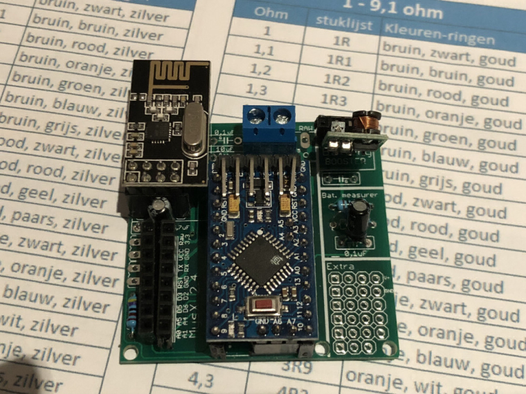
@sundberg84 Hi, I soldered a board holding a humidity and temperature sensor. That is working fine and reporting to may gateway (mqtt). Only thing which I do not get working ok is the battery level measurement. As I already posted in an other topic here.
Here are some pictures of my board. The bat jumper is connected with a wire on the bottom. And the code I use on it right now.
I already changed the pro mini for a fresh soldered one but still getting the the same result. Just ones giving the volt and % and after that only giving 0 volt as output.
tried to include delay(500) in the sketch but that did not help. So how to solve this?#define MY_NODE_ID 2 #define MY_PARENT_NODE_ID 0 #define MY_PARENT_NODE_IS_STATIC // Enable debug prints #define MY_DEBUG // Enable and select radio type attached #define MY_RADIO_NRF24 //#define MY_RADIO_RFM69 //#define MY_RS485 #include <SparkFunHTU21D.h> #include <MySensors.h> #include <Wire.h> #include <SPI.h> // Force sending an update of the temperature after n sensor reads, so a controller showing the // timestamp of the last update doesn't show something like 3 hours in the unlikely case, that // the value didn't change since; // i.e. the sensor would force sending an update every UPDATE_INTERVAL*FORCE_UPDATE_N_READS [ms] //static const uint8_t FORCE_UPDATE_N_READS = 10; #define CHILD_ID_HUM 0 #define CHILD_ID_TEMP 1 #define CHILD_ID_BATTERY 2 //#define CHILD_ID_VOLT 2 #define CHILD_ID_PRCNT 3 float lastTemp; float lastHum; uint8_t nNoUpdatesTemp; uint8_t nNoUpdatesHum; boolean metric = true; void presentation() { // Send the Sketch Version Information to the Gateway sendSketchInfo("Humidity", "2.0"); // Register all sensors to gw (they will be created as child devices) present(CHILD_ID_HUM, S_HUM); present(CHILD_ID_TEMP, S_TEMP); present(CHILD_ID_BATTERY, S_MULTIMETER); //metric = getControllerConfig().isMetric; } int BATTERY_SENSE_PIN = A0; // select the input pin for the battery sense point unsigned long SLEEP_TIME = 60000; // Sleep time between reads (in milliseconds) static int oldBatteryPcnt = 0; //Create an instance of the object HTU21D myHumidity; MyMessage msgHum(CHILD_ID_HUM, V_HUM); MyMessage msgTemp(CHILD_ID_TEMP, V_TEMP); MyMessage msgBattery(CHILD_ID_BATTERY, V_VOLTAGE); //MyMessage msgBattery(CHILD_ID_BATTERY, V_PRCNT); void setup() { myHumidity.begin(); // use the 1.1 V internal reference #if defined(__AVR_ATmega2560__) analogReference(INTERNAL1V1); #else analogReference(INTERNAL); #endif } void loop() { float temperature = myHumidity.readTemperature(); //if (!metric) { // temperature = (temperature * 1.8) + 32.0; //} send(msgTemp.set(temperature, 1)); Serial.print("T: "); Serial.println(temperature); float humidity = myHumidity.readHumidity(); send(msgHum.set(humidity, 1)); Serial.print("H: "); Serial.println(humidity); // get the battery Voltage int sensorValue = analogRead(BATTERY_SENSE_PIN); delay(500); #ifdef MY_DEBUG Serial.println(sensorValue); #endif // 1M, 470K divider across battery and using internal ADC ref of 1.1V // Sense point is bypassed with 0.1 uF cap to reduce noise at that point // ((1e6+470e3)/470e3)*1.1 = Vmax = 3.44 Volts // 3.44/1023 = Volts per bit = 0.003363075 int batteryPcnt = sensorValue / 10; #ifdef MY_DEBUG float batteryV = sensorValue * 0.003363075; Serial.print("Child ID "); Serial.print(CHILD_ID_BATTERY); Serial.print("Battery Voltage: "); Serial.print(batteryV); Serial.println(" V"); Serial.print("Battery Percent: "); Serial.print(batteryPcnt); Serial.println(" %"); #endif if (oldBatteryPcnt != batteryPcnt) { // Power up radio after sleep sendBatteryLevel(batteryPcnt); oldBatteryPcnt = batteryPcnt; } sleep(SLEEP_TIME); //sleep a bit }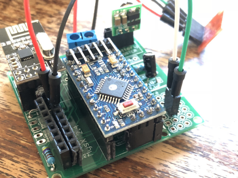
Hello! It looks like you're interested in this conversation, but you don't have an account yet.
Getting fed up of having to scroll through the same posts each visit? When you register for an account, you'll always come back to exactly where you were before, and choose to be notified of new replies (either via email, or push notification). You'll also be able to save bookmarks and upvote posts to show your appreciation to other community members.
With your input, this post could be even better 💗
Register Login