💬 Easy/Newbie PCB for MySensors
-
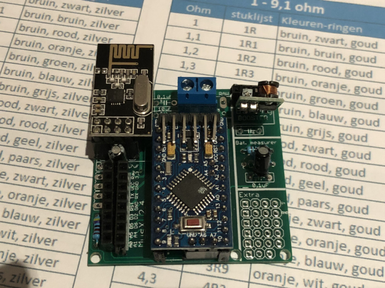
@sundberg84 Hi, I soldered a board holding a humidity and temperature sensor. That is working fine and reporting to may gateway (mqtt). Only thing which I do not get working ok is the battery level measurement. As I already posted in an other topic here.
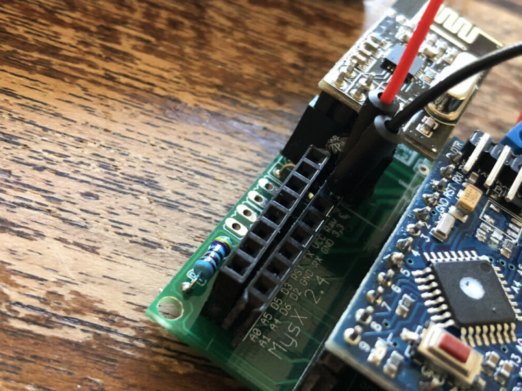
Here are some pictures of my board. The bat jumper is connected with a wire on the bottom. And the code I use on it right now.
I already changed the pro mini for a fresh soldered one but still getting the the same result. Just ones giving the volt and % and after that only giving 0 volt as output.
tried to include delay(500) in the sketch but that did not help. So how to solve this?#define MY_NODE_ID 2 #define MY_PARENT_NODE_ID 0 #define MY_PARENT_NODE_IS_STATIC // Enable debug prints #define MY_DEBUG // Enable and select radio type attached #define MY_RADIO_NRF24 //#define MY_RADIO_RFM69 //#define MY_RS485 #include <SparkFunHTU21D.h> #include <MySensors.h> #include <Wire.h> #include <SPI.h> // Force sending an update of the temperature after n sensor reads, so a controller showing the // timestamp of the last update doesn't show something like 3 hours in the unlikely case, that // the value didn't change since; // i.e. the sensor would force sending an update every UPDATE_INTERVAL*FORCE_UPDATE_N_READS [ms] //static const uint8_t FORCE_UPDATE_N_READS = 10; #define CHILD_ID_HUM 0 #define CHILD_ID_TEMP 1 #define CHILD_ID_BATTERY 2 //#define CHILD_ID_VOLT 2 #define CHILD_ID_PRCNT 3 float lastTemp; float lastHum; uint8_t nNoUpdatesTemp; uint8_t nNoUpdatesHum; boolean metric = true; void presentation() { // Send the Sketch Version Information to the Gateway sendSketchInfo("Humidity", "2.0"); // Register all sensors to gw (they will be created as child devices) present(CHILD_ID_HUM, S_HUM); present(CHILD_ID_TEMP, S_TEMP); present(CHILD_ID_BATTERY, S_MULTIMETER); //metric = getControllerConfig().isMetric; } int BATTERY_SENSE_PIN = A0; // select the input pin for the battery sense point unsigned long SLEEP_TIME = 60000; // Sleep time between reads (in milliseconds) static int oldBatteryPcnt = 0; //Create an instance of the object HTU21D myHumidity; MyMessage msgHum(CHILD_ID_HUM, V_HUM); MyMessage msgTemp(CHILD_ID_TEMP, V_TEMP); MyMessage msgBattery(CHILD_ID_BATTERY, V_VOLTAGE); //MyMessage msgBattery(CHILD_ID_BATTERY, V_PRCNT); void setup() { myHumidity.begin(); // use the 1.1 V internal reference #if defined(__AVR_ATmega2560__) analogReference(INTERNAL1V1); #else analogReference(INTERNAL); #endif } void loop() { float temperature = myHumidity.readTemperature(); //if (!metric) { // temperature = (temperature * 1.8) + 32.0; //} send(msgTemp.set(temperature, 1)); Serial.print("T: "); Serial.println(temperature); float humidity = myHumidity.readHumidity(); send(msgHum.set(humidity, 1)); Serial.print("H: "); Serial.println(humidity); // get the battery Voltage int sensorValue = analogRead(BATTERY_SENSE_PIN); delay(500); #ifdef MY_DEBUG Serial.println(sensorValue); #endif // 1M, 470K divider across battery and using internal ADC ref of 1.1V // Sense point is bypassed with 0.1 uF cap to reduce noise at that point // ((1e6+470e3)/470e3)*1.1 = Vmax = 3.44 Volts // 3.44/1023 = Volts per bit = 0.003363075 int batteryPcnt = sensorValue / 10; #ifdef MY_DEBUG float batteryV = sensorValue * 0.003363075; Serial.print("Child ID "); Serial.print(CHILD_ID_BATTERY); Serial.print("Battery Voltage: "); Serial.print(batteryV); Serial.println(" V"); Serial.print("Battery Percent: "); Serial.print(batteryPcnt); Serial.println(" %"); #endif if (oldBatteryPcnt != batteryPcnt) { // Power up radio after sleep sendBatteryLevel(batteryPcnt); oldBatteryPcnt = batteryPcnt; } sleep(SLEEP_TIME); //sleep a bit }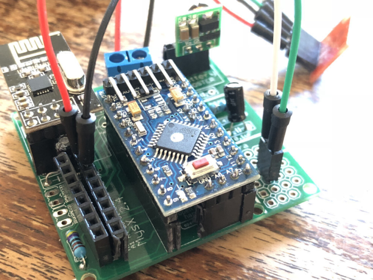
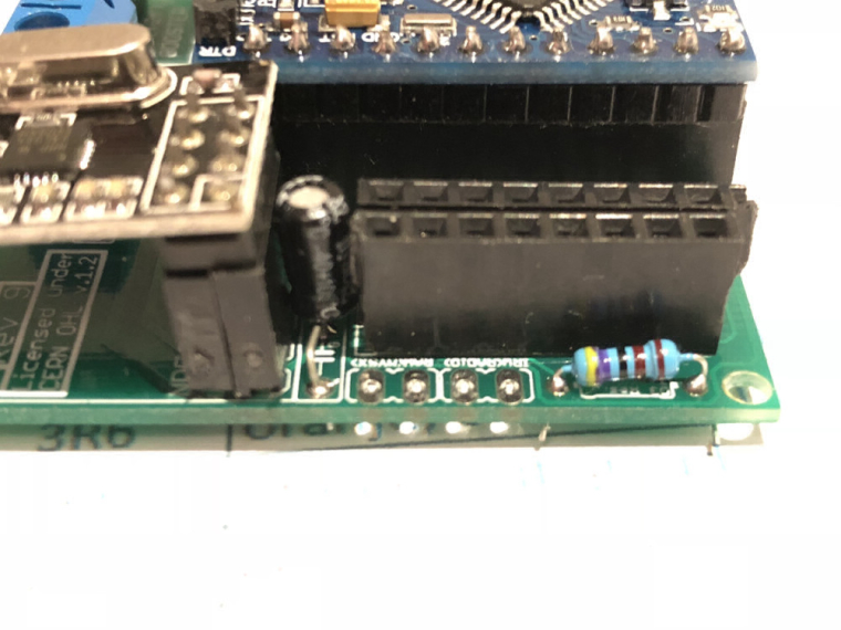
@mr_sensor - I can not see any errors on the pictures you posted.
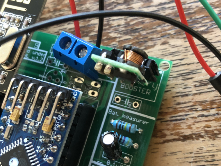
Can you measure the voltage on Booster-Vout and also on this pad.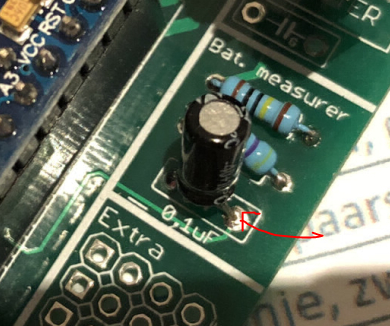
-
@mr_sensor - I can not see any errors on the pictures you posted.
Can you measure the voltage on Booster-Vout and also on this pad.@sundberg84 said in 💬 Easy/Newbie PCB for MySensors:
@mr_sensor - I can not see any errors on the pictures you posted.
Can you measure the voltage on Booster-Vout and also on this pad.I did measure the parts you mentioned. Booster is 3,36 v and the other pad is 0,00 the input strait from the batteries is 2,80 v
Also, Just for my info, does it matter how the resistors or capacitors are soldered on the board? My biggest problem is always determine the right resistors value and the right way to solder them (+ -). On the pcb some of them are coded (very handy for me as a beginner) with a G but not all of them?
So my worry was that I maybe have soldered the "battery measurer" ones in the wring direction? Could that be the problem here? -
Resistors can be soldered either way, but if you read 0v on that capacitor pin it mean you have a problem between the battery and the capacitor, so you have to backtrack the connection that is missing
@gohan said in 💬 Easy/Newbie PCB for MySensors:
Resistors can be soldered either way, but if you read 0v on that capacitor pin it mean you have a problem between the battery and the capacitor, so you have to backtrack the connection that is missing
I measured the capacitor again and get a 0,10 output.
-
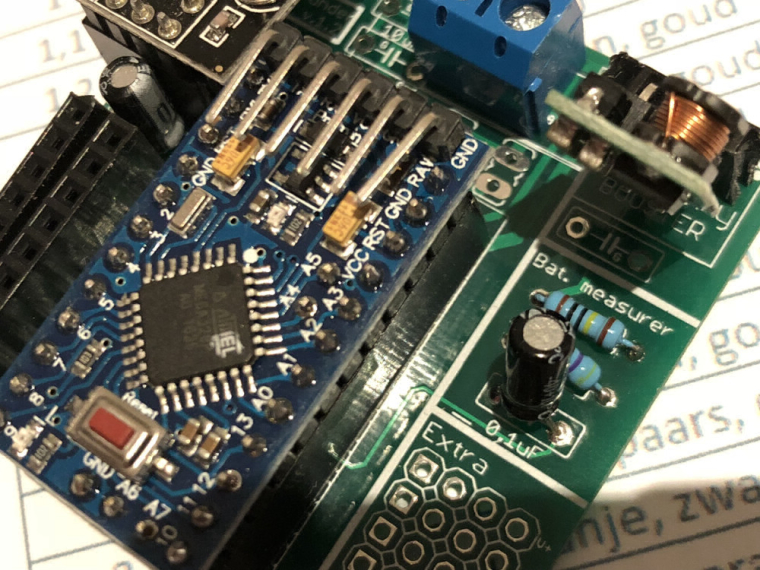
Capacitor value does not change the voltage. The resistors does... I would double check that you use the right resistors. For example it's easy to use a resistor marked 1k instead of 1M. With 3.3v you should have around 1v on the capacitor.
-
@gohan said in 💬 Easy/Newbie PCB for MySensors:
you are also missing the capacitor on the booster output for better stability
Ok, I assumed it was not needed when using a battery. Which one to use there?
@mr_sensor a advice is to measure the resistance again over the resistors.
-
@mr_sensor a advice is to measure the resistance again over the resistors.
@sundberg84 Well I tried that but did not get the measurement straight from the pcb si I decided t solder a new board using the right capacitor this time (0,1uf instead of 1uf) made sure using the right resistors as well and adding a capacitor after the booster. Than with the same mini pro from the other board tested again and wow it is working as intended.
Child ID 2Battery Voltage: 3.44 V
Battery Percent: 102 %
2930 TSF:MSG:SEND,2-2-0-0,s=255,c=3,t=0,pt=1,l=1,sg=0,ft=0,st=OK:102
2938 MCO:SLP:MS=60000,SMS=0,I1=255,M1=255,I2=255,M2=255
2945 TSF:TDI:TSL
2947 MCO:SLP:WUP=-1
2949 TSF:TRI:TSB
3065 TSF:MSG:SEND,2-2-0-0,s=1,c=1,t=0,pt=7,l=5,sg=0,ft=0,st=OK:998.0
T: 998.00
3178 TSF:MSG:SEND,2-2-0-0,s=0,c=1,t=1,pt=7,l=5,sg=0,ft=0,st=OK:998.0
H: 998.00
957
Child ID 2Battery Voltage: 3.22 V
Battery Percent: 95 %
3690 TSF:MSG:SEND,2-2-0-0,s=255,c=3,t=0,pt=1,l=1,sg=0,ft=0,st=OK:95
3698 MCO:SLP:MS=60000,SMS=0,I1=255,M1=255,I2=255,M2=255
3704 TSF:TDI:TSL
3706 MCO:SLP:WUP=-1
3708 TSF:TRI:TSB
3815 TSF:MSG:SEND,2-2-0-0,s=1,c=1,t=0,pt=7,l=5,sg=0,ft=0,st=OK:998.0
T: 998.00
3932 TSF:MSG:SEND,2-2-0-0,s=0,c=1,t=1,pt=7,l=5,sg=0,ft=0,st=OK:998.0
H: 998.00
955
Child ID 2Battery Voltage: 3.21 V
Battery Percent: 95 %
4442 MCO:SLP:MS=60000,SMS=0,I1=255,M1=255,I2=255,M2=255
4452 TSF:TDI:TSL
4454 MCO:SLP:WUP=-1
4456 TSF:TRI:TSB
4560 TSF:MSG:SEND,2-2-0-0,s=1,c=1,t=0,pt=7,l=5,sg=0,ft=0,st=OK:998.0
T: 998.00
4673 TSF:MSG:SEND,2-2-0-0,s=0,c=1,t=1,pt=7,l=5,sg=0,ft=0,st=OK:998.0
H: 998.00
953
Child ID 2Battery Voltage: 3.21 V
Battery Percent: 95 %
5185 MCO:SLP:MS=60000,SMS=0,I1=255,M1=255,I2=255,M2=255
5193 TSF:TDI:TSL
5195 MCO:SLP:WUP=-1
5197 TSF:TRI:TSB
5304 TSF:MSG:SEND,2-2-0-0,s=1,c=1,t=0,pt=7,l=5,sg=0,ft=0,st=OK:998.0
T: 998.00
5416 TSF:MSG:SEND,2-2-0-0,s=0,c=1,t=1,pt=7,l=5,sg=0,ft=0,st=OK:998.0
H: 998.00
952
Child ID 2Battery Voltage: 3.20 V
Battery Percent: 95 %
5926 MCO:SLP:MS=60000,SMS=0,I1=255,M1=255,I2=255,M2=255
5935 TSF:TDI:TSL
5939 MCO:SLP:WUP=-1
5941 TSF:TRI:TSB
6045 TSF:MSG:SEND,2-2-0-0,s=1,c=1,t=0,pt=7,l=5,sg=0,ft=0,st=OK:998.0
T: 998.00
6158 TSF:MSG:SEND,2-2-0-0,s=0,c=1,t=1,pt=7,l=5,sg=0,ft=0,st=OK:998.0
H: 998.00
952
Child ID 2Battery Voltage: 3.20 V
Battery Percent: 95 %
6670 MCO:SLP:MS=60000,SMS=0,I1=255,M1=255,I2=255,M2=255
6678 TSF:TDI:TSL
6680 MCO:SLP:WUP=-1
6682 TSF:TRI:TSB
6789 TSF:MSG:SEND,2-2-0-0,s=1,c=1,t=0,pt=7,l=5,sg=0,ft=0,st=OK:998.0
T: 998.00
6901 TSF:MSG:SEND,2-2-0-0,s=0,c=1,t=1,pt=7,l=5,sg=0,ft=0,st=OK:998.0
H: 998.00
952
Child ID 2Battery Voltage: 3.20 V
Battery Percent: 95 %
7411 MCO:SLP:MS=60000,SMS=0,I1=255,M1=255,I2=255,M2=255
7419 TSF:TDI:TSL
7424 MCO:SLP:WUP=-1
7426 TSF:TRI:TSB
7530 TSF:MSG:SEND,2-2-0-0,s=1,c=1,t=0,pt=7,l=5,sg=0,ft=0,st=OK:998.0
T: 998.00
7643 TSF:MSG:SEND,2-2-0-0,s=0,c=1,t=1,pt=7,l=5,sg=0,ft=0,st=OK:998.0
H: 998.00
952
Child ID 2Battery Voltage: 3.20 V
Battery Percent: 95 %
8155 MCO:SLP:MS=60000,SMS=0,I1=255,M1=255,I2=255,M2=255
8163 TSF:TDI:TSL
8165 MCO:SLP:WUP=-1
8167 TSF:TRI:TSB
8273 TSF:MSG:SEND,2-2-0-0,s=1,c=1,t=0,pt=7,l=5,sg=0,ft=0,st=OK:998.0
T: 998.00
8388 TSF:MSG:SEND,2-2-0-0,s=0,c=1,t=1,pt=7,l=5,sg=0,ft=0,st=OK:998.0
H: 998.00
955
Child ID 2Battery Voltage: 3.21 V
Battery Percent: 95 %
8898 MCO:SLP:MS=60000,SMS=0,I1=255,M1=255,I2=255,M2=255
8908 TSF:TDI:TSL
8910 MCO:SLP:WUP=-1
8912 TSF:TRI:TSB
9021 TSF:MSG:SEND,2-2-0-0,s=1,c=1,t=0,pt=7,l=5,sg=0,ft=0,st=OK:998.0
T: 998.00
9132 TSF:MSG:SEND,2-2-0-0,s=0,c=1,t=1,pt=7,l=5,sg=0,ft=0,st=OK:998.0
H: 998.00
948
Child ID 2Battery Voltage: 3.19 V
Battery Percent: 94 %
9646 TSF:MSG:SEND,2-2-0-0,s=255,c=3,t=0,pt=1,l=1,sg=0,ft=0,st=OK:94
9654 MCO:SLP:MS=60000,SMS=0,I1=255,M1=255,I2=255,M2=255
9660 TSF:TDI:TSL
9662 MCO:SLP:WUP=-1
9664 TSF:TRI:TSB
9771 TSF:MSG:SEND,2-2-0-0,s=1,c=1,t=0,pt=7,l=5,sg=0,ft=0,st=OK:998.0
T: 998.00
9881 TSF:MSG:SEND,2-2-0-0,s=0,c=1,t=1,pt=7,l=5,sg=0,ft=0,st=OK:998.0
H: 998.00
952
Child ID 2Battery Voltage: 3.20 V
Battery Percent: 95 %
10395 TSF:MSG:SEND,2-2-0-0,s=255,c=3,t=0,pt=1,l=1,sg=0,ft=0,st=OK:95
10403 MCO:SLP:MS=60000,SMS=0,I1=255,M1=255,I2=255,M2=255
10409 TSF:TDI:TSL
10412 MCO:SLP:WUP=-1
10414 TSF:TRI:TSB
10520 TSF:MSG:SEND,2-2-0-0,s=1,c=1,t=0,pt=7,l=5,sg=0,ft=0,st=OK:998.0
T: 998.00
10635 TSF:MSG:SEND,2-2-0-0,s=0,c=1,t=1,pt=7,l=5,sg=0,ft=0,st=OK:998.0
H: 998.00
953
Child ID 2Battery Voltage: 3.21 V
Battery Percent: 95 %
11147 MCO:SLP:MS=60000,SMS=0,I1=255,M1=255,I2=255,M2=255
11155 TSF:TDI:TSL
Now in mqtt I can see the percentage as:
95 qos : 0, retain : false, cmd : publish, dup : false, topic : **mygateway1-out/2/255/3/0/0**, messageId : , length : 30, Raw payload : 5753``` But not the voltage? -
@sundberg84 Well I tried that but did not get the measurement straight from the pcb si I decided t solder a new board using the right capacitor this time (0,1uf instead of 1uf) made sure using the right resistors as well and adding a capacitor after the booster. Than with the same mini pro from the other board tested again and wow it is working as intended.
Child ID 2Battery Voltage: 3.44 V
Battery Percent: 102 %
2930 TSF:MSG:SEND,2-2-0-0,s=255,c=3,t=0,pt=1,l=1,sg=0,ft=0,st=OK:102
2938 MCO:SLP:MS=60000,SMS=0,I1=255,M1=255,I2=255,M2=255
2945 TSF:TDI:TSL
2947 MCO:SLP:WUP=-1
2949 TSF:TRI:TSB
3065 TSF:MSG:SEND,2-2-0-0,s=1,c=1,t=0,pt=7,l=5,sg=0,ft=0,st=OK:998.0
T: 998.00
3178 TSF:MSG:SEND,2-2-0-0,s=0,c=1,t=1,pt=7,l=5,sg=0,ft=0,st=OK:998.0
H: 998.00
957
Child ID 2Battery Voltage: 3.22 V
Battery Percent: 95 %
3690 TSF:MSG:SEND,2-2-0-0,s=255,c=3,t=0,pt=1,l=1,sg=0,ft=0,st=OK:95
3698 MCO:SLP:MS=60000,SMS=0,I1=255,M1=255,I2=255,M2=255
3704 TSF:TDI:TSL
3706 MCO:SLP:WUP=-1
3708 TSF:TRI:TSB
3815 TSF:MSG:SEND,2-2-0-0,s=1,c=1,t=0,pt=7,l=5,sg=0,ft=0,st=OK:998.0
T: 998.00
3932 TSF:MSG:SEND,2-2-0-0,s=0,c=1,t=1,pt=7,l=5,sg=0,ft=0,st=OK:998.0
H: 998.00
955
Child ID 2Battery Voltage: 3.21 V
Battery Percent: 95 %
4442 MCO:SLP:MS=60000,SMS=0,I1=255,M1=255,I2=255,M2=255
4452 TSF:TDI:TSL
4454 MCO:SLP:WUP=-1
4456 TSF:TRI:TSB
4560 TSF:MSG:SEND,2-2-0-0,s=1,c=1,t=0,pt=7,l=5,sg=0,ft=0,st=OK:998.0
T: 998.00
4673 TSF:MSG:SEND,2-2-0-0,s=0,c=1,t=1,pt=7,l=5,sg=0,ft=0,st=OK:998.0
H: 998.00
953
Child ID 2Battery Voltage: 3.21 V
Battery Percent: 95 %
5185 MCO:SLP:MS=60000,SMS=0,I1=255,M1=255,I2=255,M2=255
5193 TSF:TDI:TSL
5195 MCO:SLP:WUP=-1
5197 TSF:TRI:TSB
5304 TSF:MSG:SEND,2-2-0-0,s=1,c=1,t=0,pt=7,l=5,sg=0,ft=0,st=OK:998.0
T: 998.00
5416 TSF:MSG:SEND,2-2-0-0,s=0,c=1,t=1,pt=7,l=5,sg=0,ft=0,st=OK:998.0
H: 998.00
952
Child ID 2Battery Voltage: 3.20 V
Battery Percent: 95 %
5926 MCO:SLP:MS=60000,SMS=0,I1=255,M1=255,I2=255,M2=255
5935 TSF:TDI:TSL
5939 MCO:SLP:WUP=-1
5941 TSF:TRI:TSB
6045 TSF:MSG:SEND,2-2-0-0,s=1,c=1,t=0,pt=7,l=5,sg=0,ft=0,st=OK:998.0
T: 998.00
6158 TSF:MSG:SEND,2-2-0-0,s=0,c=1,t=1,pt=7,l=5,sg=0,ft=0,st=OK:998.0
H: 998.00
952
Child ID 2Battery Voltage: 3.20 V
Battery Percent: 95 %
6670 MCO:SLP:MS=60000,SMS=0,I1=255,M1=255,I2=255,M2=255
6678 TSF:TDI:TSL
6680 MCO:SLP:WUP=-1
6682 TSF:TRI:TSB
6789 TSF:MSG:SEND,2-2-0-0,s=1,c=1,t=0,pt=7,l=5,sg=0,ft=0,st=OK:998.0
T: 998.00
6901 TSF:MSG:SEND,2-2-0-0,s=0,c=1,t=1,pt=7,l=5,sg=0,ft=0,st=OK:998.0
H: 998.00
952
Child ID 2Battery Voltage: 3.20 V
Battery Percent: 95 %
7411 MCO:SLP:MS=60000,SMS=0,I1=255,M1=255,I2=255,M2=255
7419 TSF:TDI:TSL
7424 MCO:SLP:WUP=-1
7426 TSF:TRI:TSB
7530 TSF:MSG:SEND,2-2-0-0,s=1,c=1,t=0,pt=7,l=5,sg=0,ft=0,st=OK:998.0
T: 998.00
7643 TSF:MSG:SEND,2-2-0-0,s=0,c=1,t=1,pt=7,l=5,sg=0,ft=0,st=OK:998.0
H: 998.00
952
Child ID 2Battery Voltage: 3.20 V
Battery Percent: 95 %
8155 MCO:SLP:MS=60000,SMS=0,I1=255,M1=255,I2=255,M2=255
8163 TSF:TDI:TSL
8165 MCO:SLP:WUP=-1
8167 TSF:TRI:TSB
8273 TSF:MSG:SEND,2-2-0-0,s=1,c=1,t=0,pt=7,l=5,sg=0,ft=0,st=OK:998.0
T: 998.00
8388 TSF:MSG:SEND,2-2-0-0,s=0,c=1,t=1,pt=7,l=5,sg=0,ft=0,st=OK:998.0
H: 998.00
955
Child ID 2Battery Voltage: 3.21 V
Battery Percent: 95 %
8898 MCO:SLP:MS=60000,SMS=0,I1=255,M1=255,I2=255,M2=255
8908 TSF:TDI:TSL
8910 MCO:SLP:WUP=-1
8912 TSF:TRI:TSB
9021 TSF:MSG:SEND,2-2-0-0,s=1,c=1,t=0,pt=7,l=5,sg=0,ft=0,st=OK:998.0
T: 998.00
9132 TSF:MSG:SEND,2-2-0-0,s=0,c=1,t=1,pt=7,l=5,sg=0,ft=0,st=OK:998.0
H: 998.00
948
Child ID 2Battery Voltage: 3.19 V
Battery Percent: 94 %
9646 TSF:MSG:SEND,2-2-0-0,s=255,c=3,t=0,pt=1,l=1,sg=0,ft=0,st=OK:94
9654 MCO:SLP:MS=60000,SMS=0,I1=255,M1=255,I2=255,M2=255
9660 TSF:TDI:TSL
9662 MCO:SLP:WUP=-1
9664 TSF:TRI:TSB
9771 TSF:MSG:SEND,2-2-0-0,s=1,c=1,t=0,pt=7,l=5,sg=0,ft=0,st=OK:998.0
T: 998.00
9881 TSF:MSG:SEND,2-2-0-0,s=0,c=1,t=1,pt=7,l=5,sg=0,ft=0,st=OK:998.0
H: 998.00
952
Child ID 2Battery Voltage: 3.20 V
Battery Percent: 95 %
10395 TSF:MSG:SEND,2-2-0-0,s=255,c=3,t=0,pt=1,l=1,sg=0,ft=0,st=OK:95
10403 MCO:SLP:MS=60000,SMS=0,I1=255,M1=255,I2=255,M2=255
10409 TSF:TDI:TSL
10412 MCO:SLP:WUP=-1
10414 TSF:TRI:TSB
10520 TSF:MSG:SEND,2-2-0-0,s=1,c=1,t=0,pt=7,l=5,sg=0,ft=0,st=OK:998.0
T: 998.00
10635 TSF:MSG:SEND,2-2-0-0,s=0,c=1,t=1,pt=7,l=5,sg=0,ft=0,st=OK:998.0
H: 998.00
953
Child ID 2Battery Voltage: 3.21 V
Battery Percent: 95 %
11147 MCO:SLP:MS=60000,SMS=0,I1=255,M1=255,I2=255,M2=255
11155 TSF:TDI:TSL
Now in mqtt I can see the percentage as:
95 qos : 0, retain : false, cmd : publish, dup : false, topic : **mygateway1-out/2/255/3/0/0**, messageId : , length : 30, Raw payload : 5753``` But not the voltage?@mr_sensor good to hear its working.
It looks like you are only sending the % and not the voltage? -
@Mr_sensor It happened to me once that capacitor was just shortening the circuit, it was a smd, but when I removed it and tested it it was constantly making shortage, thus the circuit was never working and luckily my power supply had a low enough protection.
I examined cap very closely, all looked fine, but internally it was not working fine.Since most of us (well, me at least) are buying cheap components I made it a habit now to always measure every passive component before installation, partly eliminates one variable
-
A short sneak-peak on the upcoming revision...
Still a long way to go...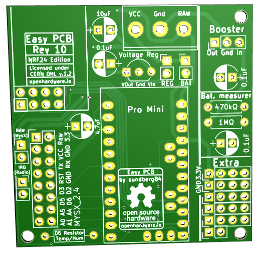
Rev 10 - Nrf24l01+ ed.
- Completley redesigned in KiCad.
- MysX location changed to accept more MysX boards and align like RFM version.
- Optional signing added
- Optional SPI flash added.
- Extra pins aligned to 2.45 vertical & horisontal
- Relocated Extra + Bat Measurer some to allow more space to booster
- Changed pull-up resistor from D3 to D5 to have one more pin for Interrupt
- Relocated D5 pullup, MysX and IRQ jumper some.
- Changed footprint (silk-screen) on capacitor to easier show Gnd/Pos side.
Need to change footprint on voltage regulator on both nrf and rfm edition back to a square and not a liniar one. (rev 9 change). Not intended to revert back.
Also a bit worried the 4,7uF cap os to far away from radio.
Controller: Proxmox VM - Home Assistant
MySensors GW: Arduino Uno - W5100 Ethernet, Gw Shield Nrf24l01+ 2,4Ghz
MySensors GW: Arduino Uno - Gw Shield RFM69, 433mhz
RFLink GW - Arduino Mega + RFLink Shield, 433mhz -
A short sneak-peak on the upcoming revision...
Still a long way to go...Rev 10 - Nrf24l01+ ed.
- Completley redesigned in KiCad.
- MysX location changed to accept more MysX boards and align like RFM version.
- Optional signing added
- Optional SPI flash added.
- Extra pins aligned to 2.45 vertical & horisontal
- Relocated Extra + Bat Measurer some to allow more space to booster
- Changed pull-up resistor from D3 to D5 to have one more pin for Interrupt
- Relocated D5 pullup, MysX and IRQ jumper some.
- Changed footprint (silk-screen) on capacitor to easier show Gnd/Pos side.
Need to change footprint on voltage regulator on both nrf and rfm edition back to a square and not a liniar one. (rev 9 change). Not intended to revert back.
Also a bit worried the 4,7uF cap os to far away from radio.
@sundberg84 said in 💬 Easy/Newbie PCB for MySensors:
Also a bit worried the 4,7uF cap os to far away from radio.
Putting it underneath the nrf24 module? I know it is not a "clean solution" but there would be still be unused space under the radio module
-
@sundberg84 said in 💬 Easy/Newbie PCB for MySensors:
Also a bit worried the 4,7uF cap os to far away from radio.
Putting it underneath the nrf24 module? I know it is not a "clean solution" but there would be still be unused space under the radio module
@gohan - thanks, not what I want to do - I have descided to have optional/more advanced on bottom side. This is the core idea of the PCB. I might revert back to Rev 9 footprint and squeeze it in like prev. revision.
-
A short sneak-peak on the upcoming revision...
Still a long way to go...Rev 10 - Nrf24l01+ ed.
- Completley redesigned in KiCad.
- MysX location changed to accept more MysX boards and align like RFM version.
- Optional signing added
- Optional SPI flash added.
- Extra pins aligned to 2.45 vertical & horisontal
- Relocated Extra + Bat Measurer some to allow more space to booster
- Changed pull-up resistor from D3 to D5 to have one more pin for Interrupt
- Relocated D5 pullup, MysX and IRQ jumper some.
- Changed footprint (silk-screen) on capacitor to easier show Gnd/Pos side.
Need to change footprint on voltage regulator on both nrf and rfm edition back to a square and not a liniar one. (rev 9 change). Not intended to revert back.
Also a bit worried the 4,7uF cap os to far away from radio.
@sundberg84 said in 💬 Easy/Newbie PCB for MySensors:
- MysX location changed to accept more MysX boards and align like RFM version.
Please don't do like that and follow the guideline for the MYSX connector (location was already wrong in previous versions and it's a bit annoying to make MYSX boards for Easy PCB):
*"The MYSX connector should be placed close to the board edge with a 100 mil spacing from all edges. The footprint has a courtyard outline to emphasize this"Also a bit worried the 4,7uF cap os to far away from radio.
I agree especially with other traces to cross before reaching the radio.
Hello! It looks like you're interested in this conversation, but you don't have an account yet.
Getting fed up of having to scroll through the same posts each visit? When you register for an account, you'll always come back to exactly where you were before, and choose to be notified of new replies (either via email, or push notification). You'll also be able to save bookmarks and upvote posts to show your appreciation to other community members.
With your input, this post could be even better 💗
Register Login