💬 Easy/Newbie PCB for MySensors
-
IS it possible to use TP4056 (https://www.aliexpress.com/item/5-pcs-Micro-USB-5V-1A-18650-TP4056-Lithium-Battery-Charger-Module-Charging-Board-With-Protection/32728720869.html?spm=a2g0s.9042311.0.0.A0lkC7) this instead of using the step up booster?
Thanks!!@hiddenuser - well not out of the box as mentioned by gohan. Im not really sure what you want to do. Its not possible to use this instead of step-up booster since it outputs 5v and the step-up needs to output 3.3v. But with a voltage regulator in between maybe? As I said - don really understand so maybe you can explain some more about your project?
Controller: Proxmox VM - Home Assistant
MySensors GW: Arduino Uno - W5100 Ethernet, Gw Shield Nrf24l01+ 2,4Ghz
MySensors GW: Arduino Uno - Gw Shield RFM69, 433mhz
RFLink GW - Arduino Mega + RFLink Shield, 433mhz -
@hiddenuser - well not out of the box as mentioned by gohan. Im not really sure what you want to do. Its not possible to use this instead of step-up booster since it outputs 5v and the step-up needs to output 3.3v. But with a voltage regulator in between maybe? As I said - don really understand so maybe you can explain some more about your project?
-
Thanks @sundberg84 and @gohan
I have used made the board for 3.3v set up as per the instruction. I have usd the output from tp4056 into the Battery connector of the board I have a step board from https://www.aliexpress.com/item/New-Electric-Unit-1-PC-NEW-DC-0-8-3-3V-to-DC-3-3V-StepUP/32724361266.html According to the specification given in the same link it is supposed to stabilize to 3.3v above 3v but the sensor reports something else back to the gateway.
@hiddenuser - well, what would a battery measurer be if it reported a constant 3.3v boosted voltage? ;)
It all depends on how everything is connected (pictures?) but if you have connected it as battery instryctions the radio and voltage divider that measured the incoming battery are not a part of the booster circuit. This to prevent noice to the radio and to be able to actually measure the battery voltage and not step-up voltage which is the idea behind the board. -
Thanks @sundberg84 and @gohan
I have used made the board for 3.3v set up as per the instruction. I have usd the output from tp4056 into the Battery connector of the board I have a step board from https://www.aliexpress.com/item/New-Electric-Unit-1-PC-NEW-DC-0-8-3-3V-to-DC-3-3V-StepUP/32724361266.html According to the specification given in the same link it is supposed to stabilize to 3.3v above 3v but the sensor reports something else back to the gateway.
-
@sundberg84 interesting question...or maybe stupid question not sure...
i have a tonn of 3v pro mini's but im thinking of mains powering some for motion sensors.... would i set it up as battery, and then just use a voltage regulator on where the step up usually would be? or is there a better way to handle it?
-
@gohan The only voltage regulator that I know of on the board is mainly for the radio. Unless you are talking the one on the pro mini.
@markjgabb If you want to do them from mains power, you might wan t to look at the HLK modules like these
https://www.ebay.com/itm/1Pcs-Power-Supply-Step-Down-Buck-Isolated-Hlk-Pm03-220V-To-3-3V-Module-New-Ic-N/332047987473?epid=571729397&hash=item4d4f9a3311:g:nyMAAOSw4GVYPa8q
Otherwise an old phone charger should work.Vera Plus running UI7 with MySensors, Sonoffs and 1-Wire devices
Visit my website for more Bits, Bytes and Ramblings from me: http://dan.bemowski.info/ -
@gohan The only voltage regulator that I know of on the board is mainly for the radio. Unless you are talking the one on the pro mini.
@markjgabb If you want to do them from mains power, you might wan t to look at the HLK modules like these
https://www.ebay.com/itm/1Pcs-Power-Supply-Step-Down-Buck-Isolated-Hlk-Pm03-220V-To-3-3V-Module-New-Ic-N/332047987473?epid=571729397&hash=item4d4f9a3311:g:nyMAAOSw4GVYPa8q
Otherwise an old phone charger should work. -
@dbemowsk cheers for that...yeah i have a tonn of old 5v bricks lying around from old nokia chargers, so was just going to try use some of them up without having to buy anythiing else, as i have all of it on hand.... i have some LE33a's which should take care of any step down issues i think?
-
@dbemowsk cheers for that...yeah i have a tonn of old 5v bricks lying around from old nokia chargers, so was just going to try use some of them up without having to buy anythiing else, as i have all of it on hand.... i have some LE33a's which should take care of any step down issues i think?
@markjgabb If you connect your 5V brick to the RAW pin, the onboard regulator on the pro mini will do.
-
@hiddenuser I'm missing how can you use a booster to get 3.3v from a lipo battery
@gohan @sundberg84
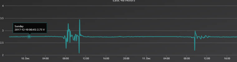
This is my setup. my battery reading is a constant 2.75v, this is not true the multi meter says ~4v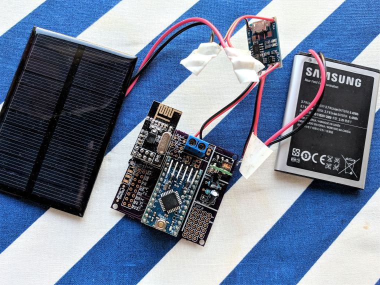
-
@markjgabb @dbemowsk @gohan - I dont have much else to add, thanks for the input here. Using mains power I would also use HLK-PM01 and input the 5v to the pro mini. If you only have 3.3v pro mini you need to input this to RAW. I have made a breakout board for the HLK module if needed as well.
https://www.openhardware.io/view/504/HLK-PM01-breakout-board
-
@gohan @sundberg84
This is my setup. my battery reading is a constant 2.75v, this is not true the multi meter says ~4vWell it looks like your battery goes to some sort of regulator before the Easy board? If so my guess is that that board is providing 2.7 v regardless of battery voltage? Have a look at @gohan and his posts about solar power and different batteries. EasyPCB is designed for 2xAA and it will not work with other voltages out of the box. The voltage divider is also dimensioned for 3.3v max and will not work with higher voltages. Again @gohan has made some experiments with this. Check his posts out. If you re-dimension the voltage divider it will work with your higher voltage.
-
@gohan @sundberg84
This is my setup. my battery reading is a constant 2.75v, this is not true the multi meter says ~4v@hiddenuser I don't know why you have a booster in place (unless it is a buck boost) and you need to change the voltage divider resistors if you want to read higher voltages (look at my solar project). In addition I'd put in place a LDO regulator if you want to use a lipo battery since a normal voltage regulator would require a higher Vin than a lipo battery can provide.
Hello! It looks like you're interested in this conversation, but you don't have an account yet.
Getting fed up of having to scroll through the same posts each visit? When you register for an account, you'll always come back to exactly where you were before, and choose to be notified of new replies (either via email, or push notification). You'll also be able to save bookmarks and upvote posts to show your appreciation to other community members.
With your input, this post could be even better 💗
Register Login