💬 jModule
-
@julisses - Be carefull...
More info here: http://forum.mysensors.org/topic/1607/safe-in-wall-ac-to-dc-transformers/ and as @m26872 said: http://forum.mysensors.org/topic/2477/are-chinese-power-supply-chargers-that-dangerous-to-use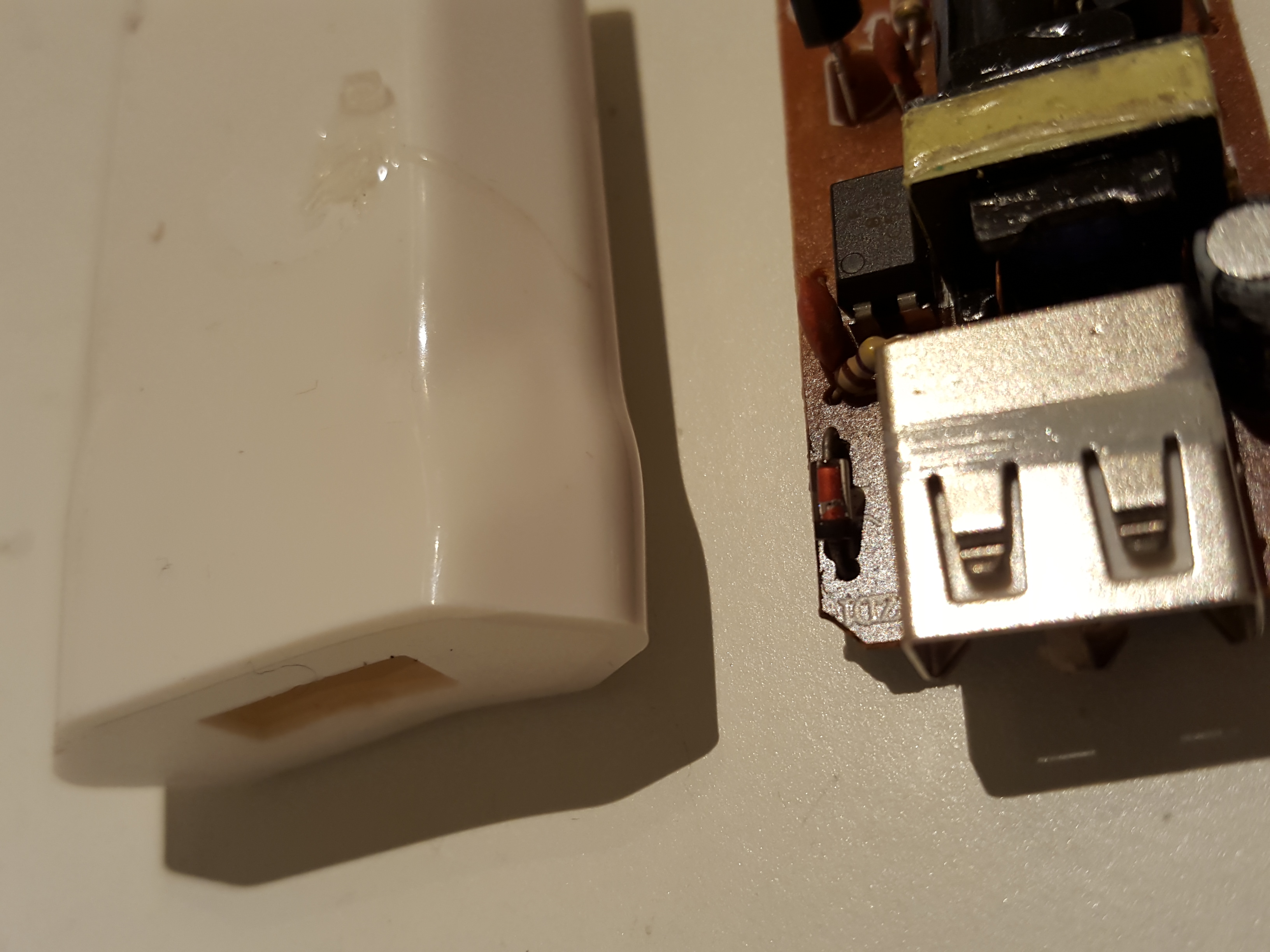
I have a couple of those cheap power supplies running some nodes and they tend to give up after some time as well...
If you look after them thats fine... but im not to comfident with those cheap usb power supplies any more.
Just a tip - as I said, have some working fine but be careful. -
Do you have a link for the angular pin-header? I noticed after soldering everything and could not get the arduino/jModule together that the angular pinheaders have the plastic in the other way. I tried with a new and just turned the pinheaders in the other way, but then the exposed pins got too short, same result when prying of every pin and turning them around manually.
-
Nice work!
Is there some kind of female plug that could be used instead? It's nicely compact--except for the male pins sticking out.
-
Regardless, I just now ordered some. Thanks!
-
OK, I "get it" now. The male pins that are sticking out are entirely optional.
-
Did anyone do any power consumption tests on these? I cannot get it below 1.5mA. I think I need to mod my Pro Mini and remove the LED and the regulator.
@alexsh1
The regulator on the board (AMS1117) consumes several mA at idle. You may need to find an alternative that has uA level quiescent current. I modified the board to use a XC6206 serial LDO (1uA standby current, see my previous post). I have the board manufactured by dirtypcb and have made sensors. Will test the battery life soon. -
@alexsh1
The regulator on the board (AMS1117) consumes several mA at idle. You may need to find an alternative that has uA level quiescent current. I modified the board to use a XC6206 serial LDO (1uA standby current, see my previous post). I have the board manufactured by dirtypcb and have made sensors. Will test the battery life soon.@ted thanks for your prompt reply. I do not have AMS1117 as I'm running Arduino Pro Mini 3.3V. I figured out it was the Mini itself. I had to remove the onboard regulator and the LED and right now my consumption is 6uA.
I'm moving away from 5V boards as I think these will be phased out eventually.Good point on AMS1117 - this is not a battery friendly regulator
-
I modified the design to use a XC6206 serial LDO (1uA standby current). I placed an order with dirtypcb. You can find the design here: http://dirtypcbs.com/view.php?share=19651&accesskey=2e5e31a83bf6fe21510c3bc438e12df7
Will update when I get the board on hand.
@ted said:
I modified the design to use a XC6206 serial LDO (1uA standby current). I placed an order with dirtypcb. You can find the design here: http://dirtypcbs.com/view.php?share=19651&accesskey=2e5e31a83bf6fe21510c3bc438e12df7
Will update when I get the board on hand.
Hello @ted, thank you for the link on dirtyPCB, I just ordered some boards. Do you have any feedback related to battery life when running at 5V ?
-
@AWI said:
@Qu3Uk I can confirm (from measuring a sample) that the large pad is not connected to anything.
However :smirk: it is hard to beat the price of an AMS1117
Thank you very much for the link, I was about to buy less units for a higher price for another board, then I remembered about seeing a link with very cheap price on this thread :)
-
Doh .. I just blindly orded this board but after checking the eagle layout .. could it be that your power wiring is messed up? The AMS1117 is chained behind the ProMini LDO which I guess is very weak. Would it be much better to put the raw-input on the jModule, power the NRF24 with the AMS1117 output and the pro mini?
-
Are the boards uploaded to DirtyPCBs good and tested? I'd very much like to order a bunch of these but I am confused by the comments about missing pads. :? Can someone please confirm?
@zilog said:
Are the boards uploaded to DirtyPCBs good and tested? I'd very much like to order a bunch of these but I am confused by the comments about missing pads. :? Can someone please confirm?
What missing pads are your talking about ?
I used the panelized version modified by @ted to use XC6206 regulator and it's running fine (though without regulator at the moment as I have not received them yet, I use CR2032). And if you use a 0.6mm PCB thickness it's really easy to cut with regular cissors.
http://dirtypcbs.com/view.php?share=19651&accesskey=2e5e31a83bf6fe21510c3bc438e12df7 -
@alexsh1
The regulator on the board (AMS1117) consumes several mA at idle. You may need to find an alternative that has uA level quiescent current. I modified the board to use a XC6206 serial LDO (1uA standby current, see my previous post). I have the board manufactured by dirtypcb and have made sensors. Will test the battery life soon. -
How about a version with the SDA & SCL pins also routed to the header?
Sensors like the Si7021 are using the I2C interface@kted said:
How about a version with the SDA & SCL pins also routed to the header?
Sensors like the Si7021 are using the I2C interfaceI agree with you and I'm going to make a slightly different version of the board, to have both those pins available and to keep antenna away from the pro mini board.
-
@EddyG said:
Any news on the new board? I am really interested.
I'm testing a first version right now :)
It's running fine but there are some annoying defaults.
I'm making improvements to the PCB now and I will publish on openhardware.io in the coming weeks.I'm using SMD NRF 24 with antenna outside for better reception. Radio capacitor is SMD also but big size (1206) so easy to solder.
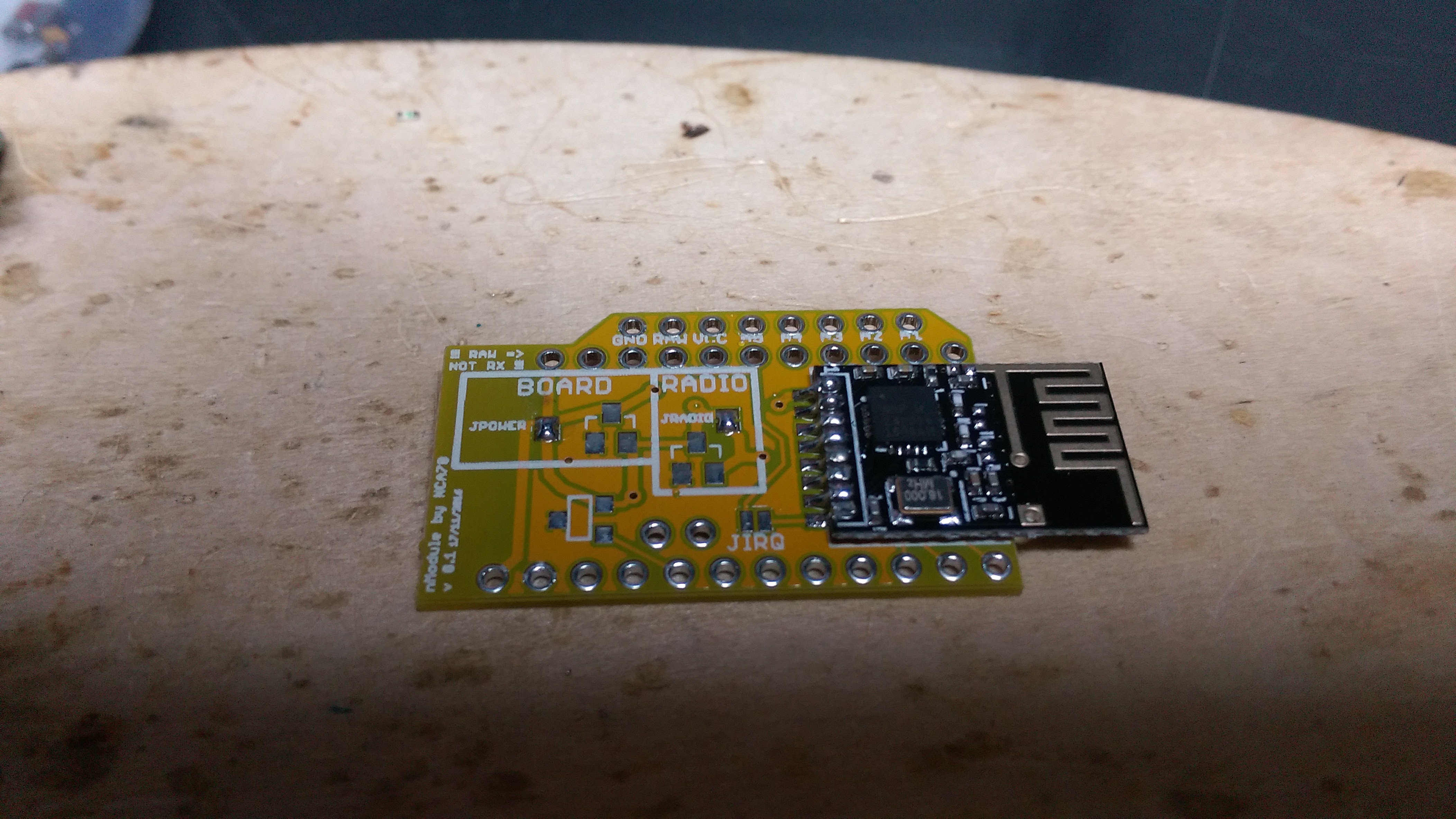
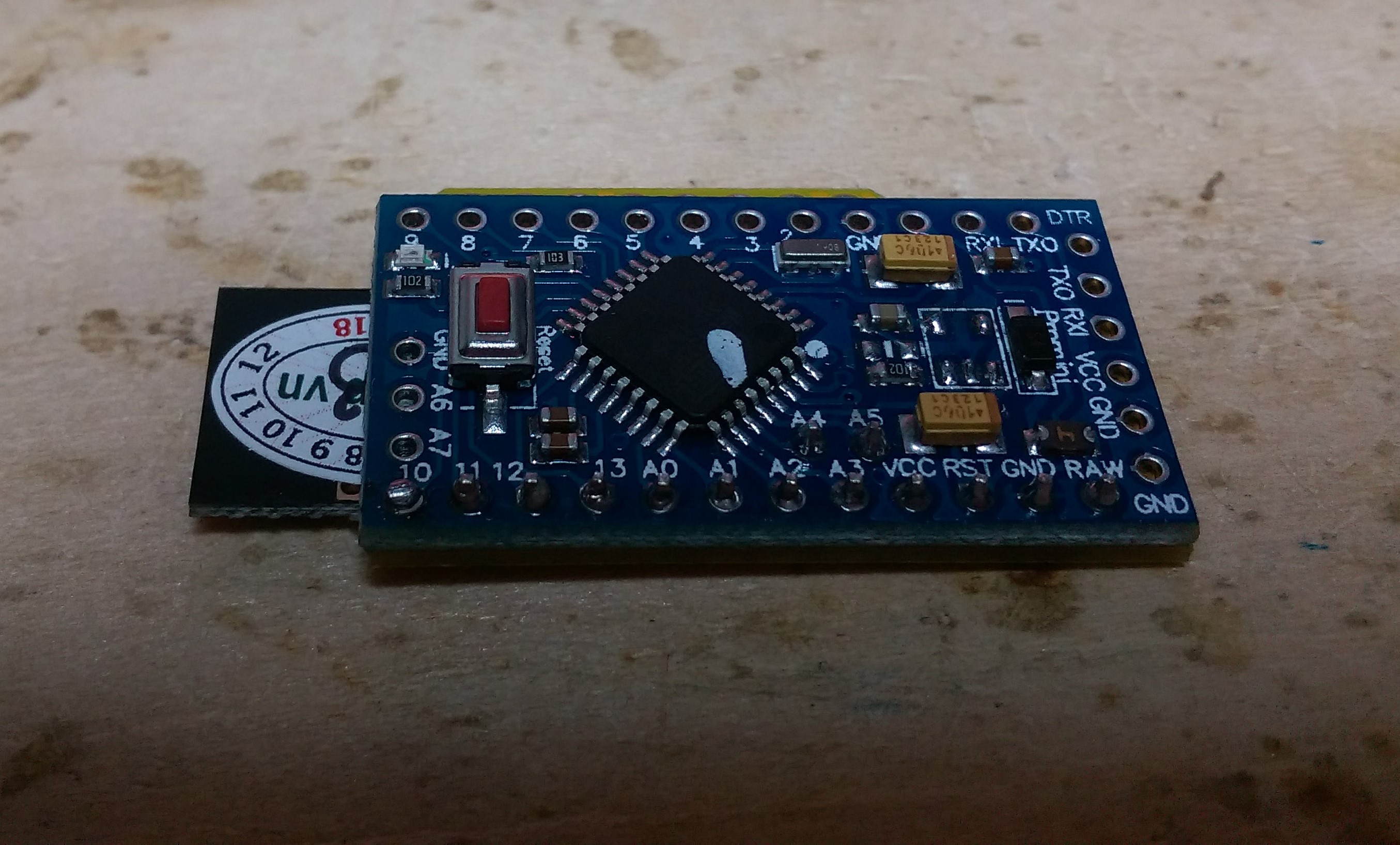
This is what the assembled board will look like, it takes a bit more surface than jModule but as you can see it's really flat, around 7mm and less than 6mm if you remove the big reset button on the pro mini.