💬 AC-DC double solid state relay module
-
Yes, it's 5x5cm.
For information, i can't place this pcb in my wall box.
I'll search other wall box this week in order to find a greater box..If someone want just to test the PCB i can sell one PCB if you are in france ;)
I have ordered 10 boards but i don't think use everything. -
Yes, it's 5x5cm.
For information, i can't place this pcb in my wall box.
I'll search other wall box this week in order to find a greater box..If someone want just to test the PCB i can sell one PCB if you are in france ;)
I have ordered 10 boards but i don't think use everything.@tonnerre33 said:
If someone want just to test the PCB i can sell one PCB if you are in france ;)
I have ordered 10 boards but i don't think use everything.Same here if you are in Vietnam or asia, just pay postage and I can send you :p
I have 20 as first order from Seeed took too long to arrive I thought it was lost, so I ordered again from PCBWay. Then received both orders.@tonnerre33 what is the space available in your wall box ? Would a 43*45mm pcb fit ? Only one relay/switch on my future board but phase + neutral in and phase + neutral out so no need to have additionnal connectors. No SMD, safe distance between tracks + milling. And 0.1'' tracks for load so it should be ok without reinforcing the tracks with solder.
-
Yes, it's 5x5cm.
For information, i can't place this pcb in my wall box.
I'll search other wall box this week in order to find a greater box..If someone want just to test the PCB i can sell one PCB if you are in france ;)
I have ordered 10 boards but i don't think use everything.@tonnerre33 Thanks buddy,
do you know if dirtypcb are still operational? because i've seen in their website that they want to migrate to another website "dangerousprototype"
did anyone order from them lately? -
@tonnerre33 Thanks buddy,
do you know if dirtypcb are still operational? because i've seen in their website that they want to migrate to another website "dangerousprototype"
did anyone order from them lately?@br0wn dev.dangerousprototypes.com is supposed to be a test site only, dirtypcb is still functional.
-
@br0wn dev.dangerousprototypes.com is supposed to be a test site only, dirtypcb is still functional.
-
@tonnerre33 said:
If someone want just to test the PCB i can sell one PCB if you are in france ;)
I have ordered 10 boards but i don't think use everything.Same here if you are in Vietnam or asia, just pay postage and I can send you :p
I have 20 as first order from Seeed took too long to arrive I thought it was lost, so I ordered again from PCBWay. Then received both orders.@tonnerre33 what is the space available in your wall box ? Would a 43*45mm pcb fit ? Only one relay/switch on my future board but phase + neutral in and phase + neutral out so no need to have additionnal connectors. No SMD, safe distance between tracks + milling. And 0.1'' tracks for load so it should be ok without reinforcing the tracks with solder.
@Nca78
I have searched others wall box today but nothing fit (box from france).
A 43x45mm pcb will fit well.
I tried the pcb of the roller-shutter-node (45x46mm) and the wall box fits well.
What do you mean by "no additionnal connectors" ? Will can use physical switches ? -
@Achim looks like a mistake in BOM (maybe that aliexpress listing has changed). Project uses same relay, but 5V version is needed.
@mr_const said:
ybe that aliexpress listing has changed). Project uses same relay, but 5V version
Uggh, I just received 20 of the 12v ones yesterday that I purchased from the BOM link. Is it safe to say that these will absolutely not work, or is there some way to adapt them with a step-up converter or something?
-
@Nca78
I have searched others wall box today but nothing fit (box from france).
A 43x45mm pcb will fit well.
I tried the pcb of the roller-shutter-node (45x46mm) and the wall box fits well.
What do you mean by "no additionnal connectors" ? Will can use physical switches ?@tonnerre33 said:
@Nca78
I have searched others wall box today but nothing fit (box from france).
A 43x45mm pcb will fit well.
I tried the pcb of the roller-shutter-node (45x46mm) and the wall box fits well.
What do you mean by "no additionnal connectors" ? Will can use physical switches ?I mean that with my future PCB you have neutral and phase in, and neutral and phase out. No need to have an extra wire from "phase in" to go to the input of the relay + a connector to connect "neutral" in to "neutral out" (that is not available on the board). At the moment with the board I installed, I have to use a wago connector for neutral which takes some extra space.
-
Hello,
Nca78 has already answered :
@Nca78 said:
@tonnerre33 said:
Hi,
can we install this module in a wall ?
Can we command shutters ?For the wall, that's the idea of keeping the 50*50mm size :)
For the shutters technically yes, but there are (at least) 2 problems :- if you have the 2 relays on at the same time = 2 directions you will probably kill the motor, there is no hardware protection on this board to avoid that (one of the relays must have power only when the other one is in off state). This can be done in software so it's not blocking.
- if you want to be able to control the level/percentage of closing, you need to measure time from min to max position, to do that you need to measure current (when motor stop consuming current it means shutter has reached it's 0% or 100% position). But there is no current sensor on this board, so you either need to implement a manual calibration process (that will lose precision over time) or use only manual control.
I am planning to test it when I have some time, and when I receive the PCB.
-
Looking to do something similar, Thanks for the contribution.
However, I'd be very concerned about using an SSR (solid state relay) vs a mechanical relay. Even in the "OFF" position there is typically a small potential/current leakage through an SSR. When using SSR nearly all applications use a secondary mechanical disconnect to truely isolate the load, for service etc. Thoughts? -
Looking to do something similar, Thanks for the contribution.
However, I'd be very concerned about using an SSR (solid state relay) vs a mechanical relay. Even in the "OFF" position there is typically a small potential/current leakage through an SSR. When using SSR nearly all applications use a secondary mechanical disconnect to truely isolate the load, for service etc. Thoughts?@Y_sam,
Nca78 highlighetd two problems:- The absence of mecanical interlock between the "up" and "down" relays, (you can use a soft interlock to prevent them from beign activated at the same time)
- The absence of a current sensor to know whether or not the shutter is fully open or fully closed : I am trying to add an ACS712, but in my case, i will know if its fully open/close if the current becomes relatively high, because the my roller shutter doesnt have limit switches and keeps running ...
-
@mr_const said:
ybe that aliexpress listing has changed). Project uses same relay, but 5V version
Uggh, I just received 20 of the 12v ones yesterday that I purchased from the BOM link. Is it safe to say that these will absolutely not work, or is there some way to adapt them with a step-up converter or something?
@JonnyDev13 said:
@mr_const said:
ybe that aliexpress listing has changed). Project uses same relay, but 5V version
Uggh, I just received 20 of the 12v ones yesterday that I purchased from the BOM link. Is it safe to say that these will absolutely not work, or is there some way to adapt them with a step-up converter or something?
You cannot adapt them with a step-up converter, there's no space on the PCB for that. But you should test them with 5V, if you are lucky they might work. I'm using 5V relays with 3.3V without any problem. The "must switch off" value in datasheet (for the original, remember what you bought is a clone...) is 0.9V which should be ok (real switch off value will probably be closer to this than to 5V) but the "must switch on" value is 8.4V which is quite far away from the 5V. The only way you will know if it will reliably switch one with 5V is to give it a try.
@okos said:
Hello.
I tried to upload my two boards ( arduino pro mini 8Mhz , 3,3 V ) modified sketches but returned to sketch Nca78 (with DS18B20), unfortunately, does not operate a physical switch. Sometimes phisical switch changes state in domoticz ( not every time ) but relays do not change state.
Switching on and switching off the lights of domoticz changes state relay without a problem.
What could be wrong ?Sorry I'm a bit short on free time at the moment, didn't have time to take a look at the sketch yet.
What you are saying is sometimes you change the physical switch position, it changes the status in domoticz, but the light status is not matching the status of the physical switch and the value of the switch in Domoticz ?For example: light is off and domoticz says off. Then you push the switch and domoticz says the light is on. But in fact the light is still off ?
-
@JonnyDev13 said:
@mr_const said:
ybe that aliexpress listing has changed). Project uses same relay, but 5V version
Uggh, I just received 20 of the 12v ones yesterday that I purchased from the BOM link. Is it safe to say that these will absolutely not work, or is there some way to adapt them with a step-up converter or something?
You cannot adapt them with a step-up converter, there's no space on the PCB for that. But you should test them with 5V, if you are lucky they might work. I'm using 5V relays with 3.3V without any problem. The "must switch off" value in datasheet (for the original, remember what you bought is a clone...) is 0.9V which should be ok (real switch off value will probably be closer to this than to 5V) but the "must switch on" value is 8.4V which is quite far away from the 5V. The only way you will know if it will reliably switch one with 5V is to give it a try.
@okos said:
Hello.
I tried to upload my two boards ( arduino pro mini 8Mhz , 3,3 V ) modified sketches but returned to sketch Nca78 (with DS18B20), unfortunately, does not operate a physical switch. Sometimes phisical switch changes state in domoticz ( not every time ) but relays do not change state.
Switching on and switching off the lights of domoticz changes state relay without a problem.
What could be wrong ?Sorry I'm a bit short on free time at the moment, didn't have time to take a look at the sketch yet.
What you are saying is sometimes you change the physical switch position, it changes the status in domoticz, but the light status is not matching the status of the physical switch and the value of the switch in Domoticz ?For example: light is off and domoticz says off. Then you push the switch and domoticz says the light is on. But in fact the light is still off ?
@Nca78 Thanks for your thoughts. I will try testing it with 5v and see what happens.
-
@tonnerre33, je suis également en France et je n'ai pas de neutre dans mes interrupteurs. Peux tu me dire comment tu as pu tester le pcb stp. Mon anglais est loin d être top desolé !!
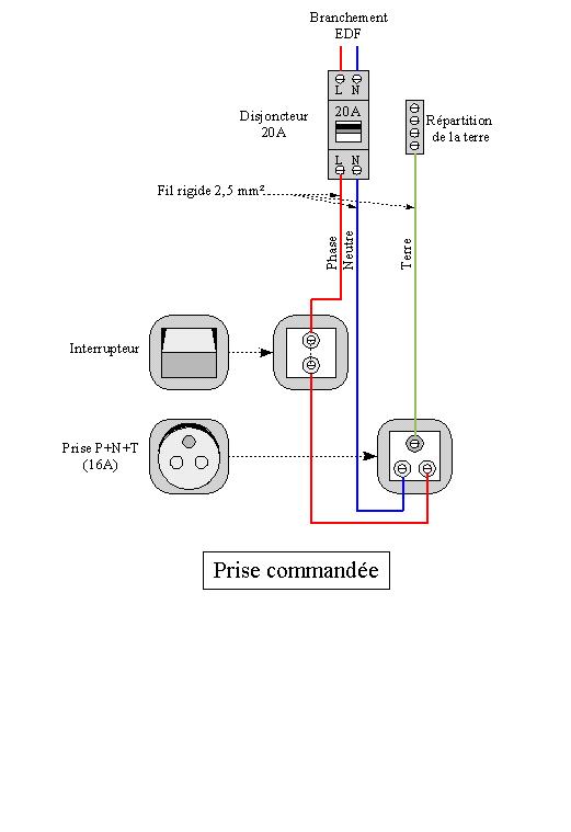
@laster13 hi, i have tried this pcb with my bedroom lamp. Indeed, these lamps are powered by electrical socket which include neutral wire.
For the others lamps, i need to find how to command them without neutral wire ;)
I am looking at this project but this is an smd project :https://www.openhardware.io/view/249/MDMSNode-Lighting
@laster13 salut, en fait mes lampes de chambres sont sur prises commandées (donc accès au neutre), du coup j'utilise ce module pour ces lampes mais pour les autres bin il va falloir que je trouve autre chose ;)
Je regarde un peu du coté de ce projet mais c'est du cms : voir le lien au dessus -
I Will tried to speak english 😗.
Thanks tonnerre33 for your help. Could you give me à shema of your installation in the bedroom ?Here is a schema of my installation without the node :
http://electric.system.free.fr/schemas/schemas/schema-prise-commandee.jpgand one with the pcb :
http://www.photorapide.com/images.php?photoName=2whnu7.png&photoId=935027
Edit : and the node with connectors :
http://www.photorapide.com/images.php?photoName=074tl3.jpg&photoId=935034
Hello! It looks like you're interested in this conversation, but you don't have an account yet.
Getting fed up of having to scroll through the same posts each visit? When you register for an account, you'll always come back to exactly where you were before, and choose to be notified of new replies (either via email, or push notification). You'll also be able to save bookmarks and upvote posts to show your appreciation to other community members.
With your input, this post could be even better 💗
Register Login