Multi Button Relay Sketch


  • Has anyone made a multi (at least 4) relay version of the relay with button sketch? the basic relay example sketch allows for multiple relays but the relay with button sketch only allows for 1. I am sure it would not be difficult for an experienced Arduino/MySensors programmer to modify the example sketch for me? Any takers?


  • Hero Member

    @SGi I have used two buttons in my Mains controller project. I have posted just the relay code below to show you what you need to do. I have not used the eeprom to store the state but you could soon add that back in. The main thing you need to do is check to see which sensor the incoming message is for.

    /**
       
       DESCRIPTION
       Based on the RelayWithButtonActuator sketch
      
    */
    
    // Enable debug prints to serial monitor
    #define MY_DEBUG
    
    // Enable and select radio type attached
    #define MY_RADIO_NRF24
    //#define MY_RADIO_RFM69
    
    // Enabled repeater feature for this node
    //#define MY_REPEATER_FEATURE
    
    #include <SPI.h>
    #include <MySensors.h>
    #include <Bounce2.h>
    
    #define RELAY_ON 1
    #define RELAY_OFF 0
    
    #define SSR_A_ID 1   // Id of the sensor child
    #define SSR_B_ID 2   // Id of the sensor child
    
    const int buttonPinA = 3;
    const int buttonPinB = 4;
    const int relayPinA = 5;
    const int relayPinB = 6;
    int oldValueA = 0;
    int oldValueB = 0;
    bool stateA = false;
    bool stateB = false;


    Bounce debouncerA = Bounce();
    Bounce debouncerB = Bounce();
    
    MyMessage msgA(SSR_A_ID, V_STATUS);
    MyMessage msgB(SSR_B_ID, V_STATUS);
    
    void setup()
    {
    
      pinMode(buttonPinA, INPUT_PULLUP); // Setup the button Activate internal pull-up
      pinMode(buttonPinB, INPUT_PULLUP); // Setup the button Activate internal pull-up
    // Then set relay pins in output mode
      pinMode(relayPinA, OUTPUT);
      pinMode(relayPinB, OUTPUT);
    
      // After setting up the buttons, setup debouncer
      debouncerA.attach(buttonPinA);
      debouncerA.interval(5);
      debouncerB.attach(buttonPinB);
      debouncerB.interval(5);
    
      // Make sure relays are off when starting up
      digitalWrite(relayPinA, RELAY_OFF);
      digitalWrite(relayPinB, RELAY_OFF);
      
      
    }
    
    void presentation()  {
      // Send the sketch version information to the gateway and Controller
      sendSketchInfo("Mains Controller", "1.0");
    
      // Register all sensors to gw (they will be created as child devices)
      present(SSR_A_ID, S_LIGHT);
      present(SSR_B_ID, S_LIGHT);
    
    }
    
    /*
       Example on how to asynchronously check for new messages from gw
    */
    void loop()
    {
      debouncerA.update();
      // Get the update value
      int valueA = debouncerA.read();
      if (valueA != oldValueA && valueA == 0) {
        send(msgA.set(stateA ? false : true), true); // Send new state and request ack back
    
      }
      oldValueA = valueA;
     
    
      debouncerB.update();
      // Get the update value
      int valueB = debouncerB.read();
      if (valueB != oldValueB && valueB == 0) {
        send(msgB.set(stateB ? false : true), true); // Send new state and request ack back
    
      }
      oldValueB = valueB;
    }
    
    void receive(const MyMessage &message) {
      // We only expect one type of message from controller. But we better check anyway.


      if (message.type == V_STATUS) {
          
        switch (message.sensor) {
          case 1:
            stateA = message.getBool();
            digitalWrite(message.sensor + 4, stateA ? RELAY_ON : RELAY_OFF);
            
            break;
          case 2:
            stateB = message.getBool();
            digitalWrite(message.sensor + 4, stateB ? RELAY_ON : RELAY_OFF);
            
            break;
          
        }
       
          // Write some debug info
        Serial.print("Incoming change for sensor:");
        Serial.println(message.sensor);
        Serial.print("from node:");
        Serial.println(message.sender);
        Serial.print(", New status: ");
        Serial.println(message.getBool());
      }
    }


  • @Boots33
    if i want use an up/down switch (no push switch) that with each change (up or down) , relay state change . for example if relay is "on" and switch is "down" , with change switch to "up" relay to be "off" OR if relay is "off" and switch is "down" , with change switch to "up" relay to be "on"
    in sketch , what am i do ?


  • Hero Member

    Haven't tried it but this might work

    move the line _____ oldValueA = valueA; ____up into the if statement

    and remove ______ && valueA == 0 ____ from the if conditional

     debouncerA.update();
      // Get the update value
      int valueA = debouncerA.read();
      if (valueA != oldValueA ) {
        send(msgA.set(stateA ? false : true), true); // Send new state and request ack back
       oldValueA = valueA;
      }


  • @Boots33
    this is great
    but have a tiny problem
    with power off/on , relay state is unstable every time . i could not fix this . can you fix ? with power off/on relay to be high every time . different state of relay and button have influence on relay state after power off/on . often with power off/on , there are a change state low to high or high to low quickly.
    in other means , in startup if switch be down or up , dont Make sure relays are off when starting up

    also state in web is not correct


  • Hero Member

    @rayan It might be easier if you post your code so we can see where the changes need to be made.


  • @Boots33
    this is your code 🙂

    #define MY_DEBUG
    #define MY_RADIO_NRF24
    #define MY_REPEATER_FEATURE
    
    #include <SPI.h>
    #include <MySensors.h>
    #include <Bounce2.h>
    
    #define RELAY_ON 1
    #define RELAY_OFF 0
    
    #define SSR_A_ID 1   // Id of the sensor child
    #define SSR_B_ID 2   // Id of the sensor child
    
    const int buttonPinA = 18;
    const int buttonPinB = 19;
    const int relayPinA = 5;
    const int relayPinB = 6;
    int oldValueA = 0;
    int oldValueB = 0;
    bool stateA = false;
    bool stateB = false;


    Bounce debouncerA = Bounce();
    Bounce debouncerB = Bounce();
    
    MyMessage msgA(SSR_A_ID, V_STATUS);
    MyMessage msgB(SSR_B_ID, V_STATUS);
    
    void setup()
    {
    
      pinMode(buttonPinA, INPUT_PULLUP); // Setup the button Activate internal pull-up
      pinMode(buttonPinB, INPUT_PULLUP); // Setup the button Activate internal pull-up
    
    
      // After setting up the buttons, setup debouncer
      debouncerA.attach(buttonPinA);
      debouncerA.interval(5);
      debouncerB.attach(buttonPinB);
      debouncerB.interval(5);
    
      // Make sure relays are off when starting up
      digitalWrite(relayPinA, RELAY_OFF);
      digitalWrite(relayPinB, RELAY_OFF);
      // Then set relay pins in output mode
      pinMode(relayPinA, OUTPUT);
      pinMode(relayPinB, OUTPUT);
      
    }
    
    void presentation()  {
      // Send the sketch version information to the gateway and Controller
      sendSketchInfo("Mains Controller", "1.0");
    
      // Register all sensors to gw (they will be created as child devices)
      present(SSR_A_ID, S_LIGHT);
      present(SSR_B_ID, S_LIGHT);
    
    }
    
    /*
       Example on how to asynchronously check for new messages from gw
    */
    void loop()
    {
      debouncerA.update();
      // Get the update value
      int valueA = debouncerA.read();
      if (valueA != oldValueA) {
        send(msgA.set(stateA ? false : true), true); // Send new state and request ack back
      oldValueA = valueA;
      }
     
    
      debouncerB.update();
      // Get the update value
      int valueB = debouncerB.read();
      if (valueB != oldValueB) {
        send(msgB.set(stateB ? false : true), true); // Send new state and request ack back
      oldValueB = valueB;
      }
    }
    
    void receive(const MyMessage &message) {
      // We only expect one type of message from controller. But we better check anyway.
      if (message.type == V_STATUS) {
          
        switch (message.sensor) {
          case 1:
            stateA = message.getBool();
            digitalWrite(message.sensor + 4, stateA ? RELAY_ON : RELAY_OFF);
            
            break;
          case 2:
            stateB = message.getBool();
            digitalWrite(message.sensor + 4, stateB ? RELAY_ON : RELAY_OFF);
            
            break;
          
        }
       
          // Write some debug info
        Serial.print("Incoming change for sensor:");
        Serial.println(message.sensor);
        Serial.print("from node:");
        Serial.println(message.sender);
        Serial.print(", New status: ");
        Serial.println(message.getBool());
      }
    }


  • you are set value for relay in code

      digitalWrite(relayPinA, RELAY_OFF);
      digitalWrite(relayPinB, RELAY_OFF);
    

    but i dont know why after start up . . .


  • Hero Member

    @rayan so are you saying that when the node is first booted up you want the relay to always to be turned on?


  • @Boots33
    i want if power of home be off and after time on again , so all of relay ( with switch up/down with each state) to be off. now in this code after startup relay is unstable for 1s and my light is on and aff quickly 🙂
    also if lights are off , if power off/on , so some of relay go to ON in startup !


  • Hero Member

    @rayan So if the house looses power you want the relays to be turned off when power is restored?


  • @Boots33
    yes, all of lights are on or off (some on some off) so when looses power and power is restored , i want all of lights be off also in web and app light = off , so with key in app or change state of switch turn on again ...


  • but this app , every time after the restored power and startup, relay ( related to state of up/down switch) have different state


  • Hero Member

    @rayan yes it was meant to be used with push buttons not toggle switches. It will need a few tweaks to make it work. I am at work now so will take a look when I get home.


  • @Boots33 said:

    @rayan yes it was meant to be used with push buttons not toggle switches. It will need a few tweaks to make it work. I am at work now so will take a look when I get home.

    ok thank you


  • Hero Member

    @rayan Ok had a quick look and I don't think we need to do a lot for this to work.
    The only extra change I have made is to add four new lines at the end of the setup function

       /*--------------------- Added these lines for toggle switch-------------------------*/
      oldValueA = digitalRead(buttonPinA);  // set oldValueA to the current status of the toggle switch
      oldValueB = digitalRead(buttonPinB);  // set oldValueB to the current status of the toggle switch
      send(msgA.set(false)); // Send off state for relayA to ensure controller knows the switch is off
      send(msgB.set(false)); // Send off state for relayB to ensure controller knows the switch is off
    

    As you can see the oldValue variables are now set to represent the current state of the toggle switches when the node boots up. this should stop any changes in state being made in the main loop until a switch is toggled.
    The other two lines just send a message to the controller to tell it the switches are off. this should make the controller icons show the correct state

    Below is the full sketch, I have nothing to test it on so give it a try and see how it goes

    #define MY_DEBUG
    #define MY_RADIO_NRF24
    #define MY_REPEATER_FEATURE
    
    #include <SPI.h>
    #include <MySensors.h>
    #include <Bounce2.h>
    
    #define RELAY_ON 1
    #define RELAY_OFF 0
    
    #define SSR_A_ID 1   // Id of the sensor child
    #define SSR_B_ID 2   // Id of the sensor child
    
    const int buttonPinA = 18;
    const int buttonPinB = 19;
    const int relayPinA = 5;
    const int relayPinB = 6;
    int oldValueA = 0;
    int oldValueB = 0;
    bool stateA = false;
    bool stateB = false;


    Bounce debouncerA = Bounce();
    Bounce debouncerB = Bounce();
    
    MyMessage msgA(SSR_A_ID, V_STATUS);
    MyMessage msgB(SSR_B_ID, V_STATUS);
    
    void setup()
    {
    
      pinMode(buttonPinA, INPUT_PULLUP); // Setup the button Activate internal pull-up
      pinMode(buttonPinB, INPUT_PULLUP); // Setup the button Activate internal pull-up
    // Then set relay pins in output mode
      pinMode(relayPinA, OUTPUT);
      pinMode(relayPinB, OUTPUT);
    
      // After setting up the buttons, setup debouncer
      debouncerA.attach(buttonPinA);
      debouncerA.interval(5);
      debouncerB.attach(buttonPinB);
      debouncerB.interval(5);
    
      // Make sure relays are off when starting up
      digitalWrite(relayPinA, RELAY_OFF);
      digitalWrite(relayPinB, RELAY_OFF);
      
    
        /*--------------------- Added these lines for toggle switch-------------------------*/
      oldValueA = digitalRead(buttonPinA);  // set oldValueA to the current status of the toggle switch
      oldValueB = digitalRead(buttonPinB);  // set oldValueB to the current status of the toggle switch
      send(msgA.set(false)); // Send off state for relayA to ensure controller knows the switch is off
      send(msgB.set(false)); // Send off state for relayB to ensure controller knows the switch is off
      
    }
    
    void presentation()  {
      // Send the sketch version information to the gateway and Controller
      sendSketchInfo("Mains Controller", "1.0");
    
      // Register all sensors to gw (they will be created as child devices)
      present(SSR_A_ID, S_LIGHT);
      present(SSR_B_ID, S_LIGHT);
    
    }
    
    /*
       Example on how to asynchronously check for new messages from gw
    */
    void loop()
    {
      debouncerA.update();
      // Get the update value
      int valueA = debouncerA.read();
      if (valueA != oldValueA) {
        send(msgA.set(stateA ? false : true), true); // Send new state and request ack back
      oldValueA = valueA;
      }
     
    
      debouncerB.update();
      // Get the update value
      int valueB = debouncerB.read();
      if (valueB != oldValueB) {
        send(msgB.set(stateB ? false : true), true); // Send new state and request ack back
      oldValueB = valueB;
      }
    }
    
    void receive(const MyMessage &message) {
      // We only expect one type of message from controller. But we better check anyway.
      if (message.type == V_STATUS) {
          
        switch (message.sensor) {
          case 1:
            stateA = message.getBool();
            digitalWrite(message.sensor + 4, stateA ? RELAY_ON : RELAY_OFF);
            
            break;
          case 2:
            stateB = message.getBool();
            digitalWrite(message.sensor + 4, stateB ? RELAY_ON : RELAY_OFF);
            
            break;
          
        }
       
          // Write some debug info
        Serial.print("Incoming change for sensor:");
        Serial.println(message.sensor);
        Serial.print("from node:");
        Serial.println(message.sender);
        Serial.print(", New status: ");
        Serial.println(message.getBool());
      }
    }


  • @Boots33 said:

    i test your code and this is excellent . but there is another tiny problem 🙂
    when relay is ON then loses power so in app relay is ON (icon) , when power is restored and relay go to OFF in app icon is ON and dont Ack for go to show Off .
    you are best in programming 🙂


  • Hero Member

    @rayan maybe trying to send the off message before the presentation stops it from sending

    try this , have moved the messages to the main loop where they will only be sent once in the first loop

    #define MY_DEBUG
    #define MY_RADIO_NRF24
    #define MY_REPEATER_FEATURE
    
    #include <SPI.h>
    #include <MySensors.h>
    #include <Bounce2.h>
    
    #define RELAY_ON 1
    #define RELAY_OFF 0
    
    #define SSR_A_ID 1   // Id of the sensor child
    #define SSR_B_ID 2   // Id of the sensor child
    
    const int buttonPinA = 18;
    const int buttonPinB = 19;
    const int relayPinA = 5;
    const int relayPinB = 6;
    int oldValueA = 0;
    int oldValueB = 0;
    bool stateA = false;
    bool stateB = false;
    int trigger = 0;
    
    
    Bounce debouncerA = Bounce();
    Bounce debouncerB = Bounce();
    
    MyMessage msgA(SSR_A_ID, V_STATUS);
    MyMessage msgB(SSR_B_ID, V_STATUS);
    
    void setup()
    {
    
      pinMode(buttonPinA, INPUT_PULLUP); // Setup the button Activate internal pull-up
      pinMode(buttonPinB, INPUT_PULLUP); // Setup the button Activate internal pull-up
    // Then set relay pins in output mode
      pinMode(relayPinA, OUTPUT);
      pinMode(relayPinB, OUTPUT);
    
      // After setting up the buttons, setup debouncer
      debouncerA.attach(buttonPinA);
      debouncerA.interval(5);
      debouncerB.attach(buttonPinB);
      debouncerB.interval(5);
    
      // Make sure relays are off when starting up
      digitalWrite(relayPinA, RELAY_OFF);
      digitalWrite(relayPinB, RELAY_OFF);
      
    
        /*--------------------- Added these lines for toggle switch-------------------------*/
      oldValueA = digitalRead(buttonPinA);  // set oldValueA to the current status of the toggle switch
      oldValueB = digitalRead(buttonPinB);  // set oldValueB to the current status of the toggle switch
     // send(msgA.set(false)); // Send off state for relayA to ensure controller knows the switch is off
     // send(msgB.set(false)); // Send off state for relayB to ensure controller knows the switch is off
      
    }
    
    void presentation()  {
      // Send the sketch version information to the gateway and Controller
      sendSketchInfo("Mains Controller", "1.0");
    
      // Register all sensors to gw (they will be created as child devices)
      present(SSR_A_ID, S_LIGHT);
      present(SSR_B_ID, S_LIGHT);
    
    }
    
    /*
       Example on how to asynchronously check for new messages from gw
    */
    void loop()
    {
    if (trigger == 0){
      send(msgA.set(false)); // Send off state for relayA to ensure controller knows the switch is off
      send(msgB.set(false)); // Send off state for relayB to ensure controller knows the switch is off
      trigger = 1;
    }
    
    
      debouncerA.update();
      // Get the update value
      int valueA = debouncerA.read();
      if (valueA != oldValueA) {
        send(msgA.set(stateA ? false : true), true); // Send new state and request ack back
      oldValueA = valueA;
      }
     
    
      debouncerB.update();
      // Get the update value
      int valueB = debouncerB.read();
      if (valueB != oldValueB) {
        send(msgB.set(stateB ? false : true), true); // Send new state and request ack back
      oldValueB = valueB;
      }
    }
    
    void receive(const MyMessage &message) {
      // We only expect one type of message from controller. But we better check anyway.
      if (message.type == V_STATUS) {
          
        switch (message.sensor) {
          case 1:
            stateA = message.getBool();
            digitalWrite(message.sensor + 4, stateA ? RELAY_ON : RELAY_OFF);
            
            break;
          case 2:
            stateB = message.getBool();
            digitalWrite(message.sensor + 4, stateB ? RELAY_ON : RELAY_OFF);
            
            break;
          
        }
       
          // Write some debug info
        Serial.print("Incoming change for sensor:");
        Serial.println(message.sensor);
        Serial.print("from node:");
        Serial.println(message.sender);
        Serial.print(", New status: ");
        Serial.println(message.getBool());
      }
    }


  • @Boots33
    great.
    so this is best sketch 🙂
    thank you


  • @Boots33
    oh , after added this device , happen a Event ! node id of motion sensor and this device is 1 ! and after sense of motion light on in dashborad ! why both Catch node id 1 .
    i dont add #define node id for motion and for this. but both take id 1 and Interference
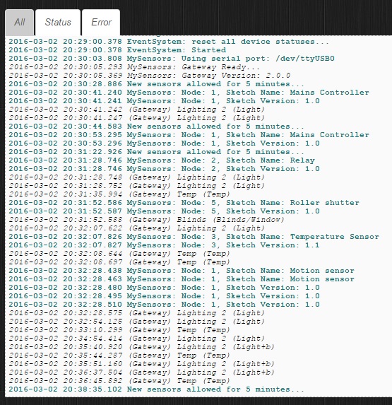
    0_1475589467935_mdmddmdmd.jpg


  • Hero Member

    @rayan As far as I am aware if you don't set the id manually then the controller gives out an id. Why it has doubled up I don't know. Did you use that arduino before and it was originally given that address?

    Anyway you will have to delete the node from the mysensors hardware device in Domiticz then clear the eeprom of that arduino using the clearEepromConfig sketch in the mysensors examples and then reload the mains switch sketch. It should then be given a new id.


  • @Boots33
    thank you very much


  • This post is deleted!


  • @Boots33 Whoa sorry, here is the code in the proper format/window...

    /**
     *******************************
     *
     * REVISION HISTORY
     * Version 0.1 - SGI
     * 
     * DESCRIPTION
     * Sketch to control 4 relays for irrigations, including 4 local push buttons.. 
     */ 
    
    // Enable debug prints to serial monitor
    #define MY_DEBUG 
    
    // Enable and select radio type attached
    #define MY_RADIO_NRF24
    //#define MY_RADIO_RFM69
    
    // Enable repeater functionality for this node
    #define MY_REPEATER_FEATURE
    
    #include <SPI.h>
    #include <MySensors.h>
    #include <Bounce2.h>
    
    // Define Relays
    #define RELAY_1  5  // Arduino Digital I/O pin number for first relay (second on pin+1 etc)
    #define NUMBER_OF_RELAYS 4 // Total number of attached relays
    #define RELAY_ON 0  // GPIO value to write to turn on attached relay
    #define RELAY_OFF 1 // GPIO value to write to turn off attached relay
    
    // Define Sensor ID's
    #define SSR_A_ID 11   // Id of the sensor child
    #define SSR_B_ID 12   // Id of the sensor child
    #define SSR_C_ID 13   // Id of the sensor child
    #define SSR_D_ID 14   // Id of the sensor child
    
    // Define Buttons
    const int buttonPinA = 1;
    const int buttonPinB = 2;
    const int buttonPinC = 3;
    const int buttonPinD = 4;
    
    // Define Variables
    int oldValueA = 0;
    int oldValueB = 0;
    int oldValueC = 0;
    int oldValueD = 0;
    bool stateA;
    bool stateB;
    bool stateC;
    bool stateD;
    
    // Define Debounce
    Bounce debouncerA = Bounce();
    Bounce debouncerB = Bounce();
    Bounce debouncerC = Bounce();
    Bounce debouncerD = Bounce();
    
    // Define messages to send back to gateway
    MyMessage msgA(SSR_A_ID, V_STATUS);
    MyMessage msgB(SSR_B_ID, V_STATUS);
    MyMessage msgC(SSR_C_ID, V_STATUS);
    MyMessage msgD(SSR_D_ID, V_STATUS);
    
    
    void setup() {
    
      // Setup relay pins and set to output then set relays to startup off
      for (int sensor=1, pin=RELAY_1; sensor<=NUMBER_OF_RELAYS;sensor++, pin++) {
        // Then set relay pins in output mode
        pinMode(pin, OUTPUT);   
        // Set relay off
        digitalWrite(pin, 1);
      }
    
      // Setup the button Activate internal pull-up
      pinMode(buttonPinA, INPUT_PULLUP); 
      pinMode(buttonPinB, INPUT_PULLUP);
      pinMode(buttonPinC, INPUT_PULLUP);
      pinMode(buttonPinD, INPUT_PULLUP);
    
      // After setting up the buttons, setup debouncer
      debouncerA.attach(buttonPinA);
      debouncerA.interval(5);
      debouncerB.attach(buttonPinB);
      debouncerB.interval(5);
      debouncerC.attach(buttonPinC);
      debouncerC.interval(5);
      debouncerD.attach(buttonPinD);
      debouncerD.interval(5);
      
    }
    
    void presentation()  
    {   
      // Send the sketch version information to the gateway and Controller
      sendSketchInfo("Irrigation with Buttons", "0.1");
      
      // Register all sensors to gw (they will be created as child devices)
      present(SSR_A_ID, S_LIGHT);
      present(SSR_B_ID, S_LIGHT);
      present(SSR_C_ID, S_LIGHT);
      present(SSR_D_ID, S_LIGHT);
    }
    
    
    void loop() 
    {
      debouncerA.update();
      // Get the update value
      int valueA = debouncerA.read();
      if (valueA != oldValueA && valueA == 0) {
        send(msgA.set(stateA?false:true), true); // Send new state and request ack back
      }
      oldValueA = valueA;
     
      debouncerB.update();
      // Get the update value
      int valueB = debouncerB.read();
      if (valueB != oldValueB && valueB == 0) {
        send(msgB.set(stateB?false:true), true); // Send new state and request ack back
      }
      oldValueB = valueB;
    
      debouncerC.update();
      // Get the update value
      int valueC = debouncerC.read();
      if (valueC != oldValueC && valueC == 0) {
        send(msgC.set(stateC ? false : true), true); // Send new state and request ack back
      }
      oldValueC = valueC;
    
      debouncerD.update();
      // Get the update value
      int valueD = debouncerD.read();
      if (valueD != oldValueD && valueD == 0) {
        send(msgD.set(stateD ? false : true), true); // Send new state and request ack back
      }
      oldValueD = valueD;  
    }
    
    void receive(const MyMessage &message) {
      // We only expect one type of message from controller. But we better check anyway.
      if (message.type==V_STATUS) {
         
        switch (message.sensor) {
          case 1:
            stateA = message.getBool();
            digitalWrite(message.sensor+4, stateA ? RELAY_ON : RELAY_OFF);
            break;
          case 2:
            stateB = message.getBool();
            digitalWrite(message.sensor+4, stateB ? RELAY_ON : RELAY_OFF);
            break;
          case 3:
            stateC = message.getBool();
            digitalWrite(message.sensor+4, stateC ? RELAY_ON : RELAY_OFF);
            break;
          case 4:
            stateD = message.getBool();
            digitalWrite(message.sensor+4, stateD ? RELAY_ON : RELAY_OFF);
            break;
            }
         // Change relay state
         // digitalWrite(message.sensor-1+RELAY_1, message.getBool()?RELAY_ON:RELAY_OFF);
         // Store state in eeprom
         //saveState(message.sensor, message.getBool());
         // Write some debug info
         Serial.print("Incoming change for sensor:");
         Serial.print(message.sensor);
         Serial.print(", New status: ");
         Serial.println(message.getBool());
       } 
    }


  • @Boots33 i just worked out what was wrong the code above... and now understand how the message.sensor number works... now my only issue is why the buttons on pins 2,3,4 work but not pin 1... does pin 1 on the arduino have special use?


  • Hero Member

    @SGi great that you worked it out and improved your understanding of mysensors as well. 😊. Probably good to post the fix so others may also gain from the thread.

    I think digital pins 0 and 1 are also used for serial communication so probably best to avoid them wherever possible. If you turn off debugging they will probably work but you may have problems uploading sketches too. The analogue pins can also be used as digital pins if you need a few more.


  • @Boots33 said:

    @rayan maybe trying to send the off message before the presentation stops it from sending

    try this , have moved the messages to the main loop where they will only be sent once in the first loop

    #define MY_DEBUG
    #define MY_RADIO_NRF24
    #define MY_REPEATER_FEATURE
    
    #include <SPI.h>
    #include <MySensors.h>
    #include <Bounce2.h>
    
    #define RELAY_ON 1
    #define RELAY_OFF 0
    
    #define SSR_A_ID 1   // Id of the sensor child
    #define SSR_B_ID 2   // Id of the sensor child
    
    const int buttonPinA = 18;
    const int buttonPinB = 19;
    const int relayPinA = 5;
    const int relayPinB = 6;
    int oldValueA = 0;
    int oldValueB = 0;
    bool stateA = false;
    bool stateB = false;
    int trigger = 0;
    
    
    Bounce debouncerA = Bounce();
    Bounce debouncerB = Bounce();
    
    MyMessage msgA(SSR_A_ID, V_STATUS);
    MyMessage msgB(SSR_B_ID, V_STATUS);
    
    void setup()
    {
    
      pinMode(buttonPinA, INPUT_PULLUP); // Setup the button Activate internal pull-up
      pinMode(buttonPinB, INPUT_PULLUP); // Setup the button Activate internal pull-up
    
    
      // After setting up the buttons, setup debouncer
      debouncerA.attach(buttonPinA);
      debouncerA.interval(5);
      debouncerB.attach(buttonPinB);
      debouncerB.interval(5);
    
      // Make sure relays are off when starting up
      digitalWrite(relayPinA, RELAY_OFF);
      digitalWrite(relayPinB, RELAY_OFF);
      // Then set relay pins in output mode
      pinMode(relayPinA, OUTPUT);
      pinMode(relayPinB, OUTPUT);
    
        /*--------------------- Added these lines for toggle switch-------------------------*/
      oldValueA = digitalRead(buttonPinA);  // set oldValueA to the current status of the toggle switch
      oldValueB = digitalRead(buttonPinB);  // set oldValueB to the current status of the toggle switch
     // send(msgA.set(false)); // Send off state for relayA to ensure controller knows the switch is off
     // send(msgB.set(false)); // Send off state for relayB to ensure controller knows the switch is off
      
    }
    
    void presentation()  {
      // Send the sketch version information to the gateway and Controller
      sendSketchInfo("Mains Controller", "1.0");
    
      // Register all sensors to gw (they will be created as child devices)
      present(SSR_A_ID, S_LIGHT);
      present(SSR_B_ID, S_LIGHT);
    
    }
    
    /*
       Example on how to asynchronously check for new messages from gw
    */
    void loop()
    {
    if (trigger == 0){
      send(msgA.set(false)); // Send off state for relayA to ensure controller knows the switch is off
      send(msgB.set(false)); // Send off state for relayB to ensure controller knows the switch is off
      trigger = 1;
    }
    
    
      debouncerA.update();
      // Get the update value
      int valueA = debouncerA.read();
      if (valueA != oldValueA) {
        send(msgA.set(stateA ? false : true), true); // Send new state and request ack back
      oldValueA = valueA;
      }
     
    
      debouncerB.update();
      // Get the update value
      int valueB = debouncerB.read();
      if (valueB != oldValueB) {
        send(msgB.set(stateB ? false : true), true); // Send new state and request ack back
      oldValueB = valueB;
      }
    }
    
    void receive(const MyMessage &message) {
      // We only expect one type of message from controller. But we better check anyway.
      if (message.type == V_STATUS) {
          
        switch (message.sensor) {
          case 1:
            stateA = message.getBool();
            digitalWrite(message.sensor + 4, stateA ? RELAY_ON : RELAY_OFF);
            
            break;
          case 2:
            stateB = message.getBool();
            digitalWrite(message.sensor + 4, stateB ? RELAY_ON : RELAY_OFF);
            
            break;
          
        }
       
          // Write some debug info
        Serial.print("Incoming change for sensor:");
        Serial.println(message.sensor);
        Serial.print("from node:");
        Serial.println(message.sender);
        Serial.print(", New status: ");
        Serial.println(message.getBool());
      }
    }
    

    Thanks this code works ok. But by switch i must still connect to GND to keep change status. Is possible to change it to give only impuls GND to change status Relay ? I want use switch monostable.

    And anybody tell me how i can clear all eeprom in my Arduino Mini Pro. I want clear eeprom before upload sketch.


  • @pepson
    go to : file > examples > mysensors > clear eeprom config
    and select arduino pro mini from : tools > board > arduino pro or pro mini


  • @Boots33 this your code is good, but there is a small issue .button work just when the connection is ok (radio with gateway) ! and when radio is disconnect or controller is off, so button dont work handy . do you have any idea for this ? that when controller is off the button work handy


  • @rayan
    Hi
    I do this eeprom clear and after that when i upload sketch for relay with buttons , this not working. Any communication with Gateway. Upload sketch successful write.

    I need changes in code to button monostable. Now if i want enable RELAY i must still connect pin to GND by button. I want only give impuls GND and relay should have enable. Again give impuls GND should disable relay. The same as working Fibaro relay switch by Z-Wave.

    In code should be add option to select buttons:
    -Monostable
    -Bistable


  • @pepson
    i am beginner and i hope some one help to you


  • Maybe @Boots33 or @SGi help us please


  • Hero Member

    Here is an example that I'm using with 4 relays and 4 monostable buttons:

    // Enable debug prints to serial monitor
    #define MY_DEBUG
    
    // Enable and select radio type attached
    #define MY_RADIO_NRF24
    
    #define SN "RelayButtonArray"
    #define SV "1.0"
    
    #include <MySensors.h>
    #include <SPI.h>
    #include <Bounce2.h>
    #define RELAY_ON 0                      // switch around for ACTIVE LOW / ACTIVE HIGH relay
    #define RELAY_OFF 1
    //
    
    #define noRelays 4                     //2-4
    const int relayPin[] = {14, 15, 16, 17};       //  switch around pins to your desire
    const int buttonPin[] = {6, 7, 4, 5};   //  switch around pins to your desire
    
    class Relay             // relay class, store all relevant data (equivalent to struct)
    {
      public:
        int buttonPin;                   // physical pin number of button
        int relayPin;             // physical pin number of relay
        boolean relayState;               // relay status (also stored in EEPROM)
    };
    
    Relay Relays[noRelays];
    Bounce debouncer[noRelays];
    MyMessage msg[noRelays];
    
    /*
      void before() {
      for (int sensor=1, pin=RELAY_1; sensor<=NUMBER_OF_RELAYS;sensor++, pin++) {
        // Then set relay pins in output mode
        pinMode(pin, OUTPUT);
        // Set relay to last known state (using eeprom storage)
        digitalWrite(pin, loadState(sensor)?RELAY_ON:RELAY_OFF);
      }
      }*/
    
    void setup() {
      wait(100);
      // Initialize Relays with corresponding buttons
      for (int i = 0; i < noRelays; i++) {
        Relays[i].buttonPin = buttonPin[i];              // assign physical pins
        Relays[i].relayPin = relayPin[i];
        msg[i].sensor = i;                                   // initialize messages
        msg[i].type = V_LIGHT;
        pinMode(Relays[i].buttonPin, INPUT_PULLUP);
        wait(100);
        pinMode(Relays[i].relayPin, OUTPUT);
        Relays[i].relayState = loadState(i);                               // retrieve last values from EEPROM
        digitalWrite(Relays[i].relayPin, Relays[i].relayState ? RELAY_ON : RELAY_OFF); // and set relays accordingly
        send(msg[i].set(Relays[i].relayState ? true : false));                 // make controller aware of last status
        wait(50);
        debouncer[i] = Bounce();                        // initialize debouncer
        debouncer[i].attach(buttonPin[i]);
        debouncer[i].interval(30);
        wait(50);
      }
    }
    
    void presentation()
    {
      // Send the sketch version information to the gateway and Controller
      sendSketchInfo(SN, SV);
    
      wait(100);
    
      for (int i = 0; i < noRelays; i++)
        present(i, S_LIGHT);                               // present sensor to gateway
    
      wait(100);
    }
    
    
    void loop()
    {
      for (byte i = 0; i < noRelays; i++) {
        if (debouncer[i].update()) {
          
          int value = debouncer[i].read();
          
          if ( value == LOW) {
            Relays[i].relayState = !Relays[i].relayState;
            digitalWrite(Relays[i].relayPin, Relays[i].relayState ? RELAY_ON : RELAY_OFF);
            send(msg[i].set(Relays[i].relayState ? true : false));
            // save sensor state in EEPROM (location == sensor number)
            saveState( i, Relays[i].relayState );
    
          }
    
        }
      }
      //wait(20);
    }
    
    void receive(const MyMessage &message) {
      if (message.type == V_LIGHT) {
        if (message.sensor < noRelays) {          // check if message is valid for relays..... previous line  [[[ if (message.sensor <=noRelays){ ]]]
          Relays[message.sensor].relayState = message.getBool();
          digitalWrite(Relays[message.sensor].relayPin, Relays[message.sensor].relayState ? RELAY_ON : RELAY_OFF); // and set relays accordingly
          saveState( message.sensor, Relays[message.sensor].relayState ); // save sensor state in EEPROM (location == sensor number)
        }
      }
      wait(20);
    }
    

  • Hero Member

    @pepson The sketch i have in my first post at the top of the page will work for a push button. the one you are using has been modified for use with a toggle switch.


  • ok i test your first sketch. But maybe you can create sketch where we can setvin sketch what button we want use ?


  • Hero Member

    I'm the sketch I'm using you can freely define what pins you want to use:

    const int relayPin[] = {14, 15, 16, 17};       //  switch around pins to your desire
    const int buttonPin[] = {6, 7, 4, 5};   //  switch around pins to your desire
    

  • Hero Member

    @rayan said:

    this your code is good, but there is a small issue .button work just when the connection is ok (radio with gateway) ! and when radio is disconnect or controller is off, so button dont work handy . do you have any idea for this ? that when controller is off the button work handy

    As far as I know that is the way Mysensors works at the moment, if the node boots up and cannot find the gateway then it wont run the loop part of the sketch.
    If the gateway drops out after the node has booted then the loop part of the sketch will still run while the node tries to re-establish the connection. Because the sketch relies on an ACK back from the gateway to toggle the relay it still wont work if the gateway is down.

    You could modify the sketch so it does not rely on the ACK. This would at least allow it to work if the gateway goes down after the node has booted.
    Another way to ensure the switch will operate would be to add some circuit to override the node, like discussed Here

    Have made a quick change to the sketch so it does not need the ACK. I have not tried it but give it a go and see if it works

    #define MY_DEBUG
    #define MY_RADIO_NRF24
    #define MY_REPEATER_FEATURE
    
    #include <SPI.h>
    #include <MySensors.h>
    #include <Bounce2.h>
    
    #define RELAY_ON 1
    #define RELAY_OFF 0
    
    #define SSR_A_ID 1   // Id of the sensor child
    #define SSR_B_ID 2   // Id of the sensor child
    
    const int buttonPinA = 18;
    const int buttonPinB = 19;
    const int relayPinA = 5;
    const int relayPinB = 6;
    int oldValueA = 0;
    int oldValueB = 0;
    bool stateA = false;
    bool stateB = false;
    int trigger = 0;
    
    
    Bounce debouncerA = Bounce();
    Bounce debouncerB = Bounce();
    
    MyMessage msgA(SSR_A_ID, V_STATUS);
    MyMessage msgB(SSR_B_ID, V_STATUS);
    
    void setup()
    {
    
      pinMode(buttonPinA, INPUT_PULLUP); // Setup the button Activate internal pull-up
      pinMode(buttonPinB, INPUT_PULLUP); // Setup the button Activate internal pull-up
    // Then set relay pins in output mode
      pinMode(relayPinA, OUTPUT);
      pinMode(relayPinB, OUTPUT);
    
      // After setting up the buttons, setup debouncer
      debouncerA.attach(buttonPinA);
      debouncerA.interval(5);
      debouncerB.attach(buttonPinB);
      debouncerB.interval(5);
    
      // Make sure relays are off when starting up
      digitalWrite(relayPinA, RELAY_OFF);
      digitalWrite(relayPinB, RELAY_OFF);
      
    
        /*--------------------- Added these lines for toggle switch-------------------------*/
      oldValueA = digitalRead(buttonPinA);  // set oldValueA to the current status of the toggle switch
      oldValueB = digitalRead(buttonPinB);  // set oldValueB to the current status of the toggle switch
     // send(msgA.set(false)); // Send off state for relayA to ensure controller knows the switch is off
     // send(msgB.set(false)); // Send off state for relayB to ensure controller knows the switch is off
      
    }
    
    void presentation()  {
      // Send the sketch version information to the gateway and Controller
      sendSketchInfo("Mains Controller", "1.0");
    
      // Register all sensors to gw (they will be created as child devices)
      present(SSR_A_ID, S_LIGHT);
      present(SSR_B_ID, S_LIGHT);
    
    }
    
    /*
       Example on how to asynchronously check for new messages from gw
    */
    void loop()
    {
    if (trigger == 0){
      send(msgA.set(false)); // Send off state for relayA to ensure controller knows the switch is off
      send(msgB.set(false)); // Send off state for relayB to ensure controller knows the switch is off
      trigger = 1;
    }
    
    
      debouncerA.update();
      // Get the update value
      int valueA = debouncerA.read();
      if (valueA != oldValueA) {
       // send(msgA.set(stateA ? false : true), true); // Send new state and request ack back
        send(msgA.set(stateA ? false : true), false); // Send new state with no request for ack
        stateA = stateA ? false : true;               // invert the state
         digitalWrite(relayPinA, stateA ? RELAY_ON : RELAY_OFF);  // toggle the relay
      oldValueA = valueA;
      }
     
    
      debouncerB.update();
      // Get the update value
      int valueB = debouncerB.read();
      if (valueB != oldValueB) {
        //send(msgB.set(stateB ? false : true), true); // Send new state and request ack back
        send(msgB.set(stateB ? false : true), false); // Send new state with no request for ack
        stateB = stateB ? false : true;                // invert the state
         digitalWrite(relayPinB, stateB ? RELAY_ON : RELAY_OFF);  // toggle the relay
        
      oldValueB = valueB;
      }
    }
    
    void receive(const MyMessage &message) {
      // We only expect one type of message from controller. But we better check anyway.
      if (message.type == V_STATUS) {
          
        switch (message.sensor) {
          case 1:
            stateA = message.getBool();
            digitalWrite(message.sensor + 4, stateA ? RELAY_ON : RELAY_OFF);
            
            break;
          case 2:
            stateB = message.getBool();
            digitalWrite(message.sensor + 4, stateB ? RELAY_ON : RELAY_OFF);
            
            break;
          
        }
       
          // Write some debug info
        Serial.print("Incoming change for sensor:");
        Serial.println(message.sensor);
        Serial.print("from node:");
        Serial.println(message.sender);
        Serial.print(", New status: ");
        Serial.println(message.getBool());
      }
    }


  • ok then i test it.
    But can you also add option to set mode button ? Bistable and monostable ?


  • @Boots33
    ack is important , so we can not found any solution for this ? for exapmle add a code to this sketch , that when radio is disconnect so without ack work and when radio is ok this way stop and with ack work again.
    this idea is for when a radio have problem or fail or other reason... so this light or other divece dont stop working and work handy when radio go to correct or change radio....

    if you can change your code and add this option , so your sketch is best code for light control


  • @korttoma your sketch not working for me. I change numer relay to 2 and change pin buttons and relay and not control relay.

    @Boots33
    Ok i correct your sketch and use:

    Switch Bistable:

    /**
       DESCRIPTION
       Sketch for 2x relay with buttons bistable. After back power all relays set OFF and send correct status OFF to controller.  
    */
    
    // Enable debug prints to serial monitor
    #define MY_DEBUG
    
    // Enable and select radio type attached
    #define MY_RADIO_NRF24
    //#define MY_RADIO_RFM69
    
    // Enabled repeater feature for this node
    #define MY_REPEATER_FEATURE
    
    #include <SPI.h>
    #include <MySensors.h>
    #include <Bounce2.h>
    
    // Define Relays
    #define RELAY_ON 1  // GPIO value to write to turn on attached relay
    #define RELAY_OFF 0  // GPIO value to write to turn off attached relay
    
    // Define Sensor ID's
    #define SSR_A_ID 1   // Id of the sensor child
    #define SSR_B_ID 2   // Id of the sensor child
    
    // Define buttons and relays
    const int buttonPinA = 3;
    const int buttonPinB = 4;
    const int relayPinA = 5;
    const int relayPinB = 6;
    
    // Define Variables
    int oldValueA = 0;
    int oldValueB = 0;
    bool stateA = false;
    bool stateB = false;
    int trigger = 0;
    
    
    Bounce debouncerA = Bounce();
    Bounce debouncerB = Bounce();
    
    MyMessage msgA(SSR_A_ID, V_STATUS);
    MyMessage msgB(SSR_B_ID, V_STATUS);
    
    void setup()
    {
    
      pinMode(buttonPinA, INPUT_PULLUP); // Setup the button Activate internal pull-up
      pinMode(buttonPinB, INPUT_PULLUP); // Setup the button Activate internal pull-up
    
    
      // After setting up the buttons, setup debouncer
      debouncerA.attach(buttonPinA);
      debouncerA.interval(5);
      debouncerB.attach(buttonPinB);
      debouncerB.interval(5);
    
      // Make sure relays are off when starting up
      digitalWrite(relayPinA, RELAY_OFF);
      digitalWrite(relayPinB, RELAY_OFF);
      // Then set relay pins in output mode
      pinMode(relayPinA, OUTPUT);
      pinMode(relayPinB, OUTPUT);
    
        /*--------------------- Added these lines for toggle switch-------------------------*/
      oldValueA = digitalRead(buttonPinA);  // set oldValueA to the current status of the toggle switch
      oldValueB = digitalRead(buttonPinB);  // set oldValueB to the current status of the toggle switch
     // send(msgA.set(false)); // Send off state for relayA to ensure controller knows the switch is off
     // send(msgB.set(false)); // Send off state for relayB to ensure controller knows the switch is off
      
    }
    
    void presentation()  {
      // Send the sketch version information to the gateway and Controller
      sendSketchInfo("2xRelay with bistable", "1.1");
    
      // Register all sensors to gw (they will be created as child devices)
      present(SSR_A_ID, S_LIGHT);
      present(SSR_B_ID, S_LIGHT);
    
    }
    
    /*
       Example on how to asynchronously check for new messages from gw
    */
    void loop()
    {
    if (trigger == 0){
      send(msgA.set(false)); // Send off state for relayA to ensure controller knows the switch is off
      send(msgB.set(false)); // Send off state for relayB to ensure controller knows the switch is off
      trigger = 1;
    }
    
    
      debouncerA.update();
      // Get the update value
      int valueA = debouncerA.read();
      if (valueA != oldValueA) {
       // send(msgA.set(stateA ? false : true), true); // Send new state and request ack back
        send(msgA.set(stateA ? false : true), false); // Send new state with no request for ack
        stateA = stateA ? false : true;               // invert the state
         digitalWrite(relayPinA, stateA ? RELAY_ON : RELAY_OFF);  // toggle the relay
      oldValueA = valueA;
      }
     
    
      debouncerB.update();
      // Get the update value
      int valueB = debouncerB.read();
      if (valueB != oldValueB) {
        //send(msgB.set(stateB ? false : true), true); // Send new state and request ack back
        send(msgB.set(stateB ? false : true), false); // Send new state with no request for ack
        stateB = stateB ? false : true;                // invert the state
         digitalWrite(relayPinB, stateB ? RELAY_ON : RELAY_OFF);  // toggle the relay
        
      oldValueB = valueB;
      }
    }
    
    void receive(const MyMessage &message) {
      // We only expect one type of message from controller. But we better check anyway.
      if (message.type == V_STATUS) {
          
        switch (message.sensor) {
          case 1:
            stateA = message.getBool();
            digitalWrite(message.sensor + 4, stateA ? RELAY_ON : RELAY_OFF);
            
            break;
          case 2:
            stateB = message.getBool();
            digitalWrite(message.sensor + 4, stateB ? RELAY_ON : RELAY_OFF);
            
            break;
          
        }
       
          // Write some debug info
        Serial.print("Incoming change for sensor:");
        Serial.println(message.sensor);
        Serial.print("from node:");
        Serial.println(message.sender);
        Serial.print(", New status: ");
        Serial.println(message.getBool());
      }
    }
    

    Switch monostable:

    /**
       DESCRIPTION
       Sketch for 2x relay with buttons monostable. After back power all relays set OFF and send correct status OFF to controller.  
    */
    
    // Enable debug prints to serial monitor
    #define MY_DEBUG
    
    // Enable and select radio type attached
    #define MY_RADIO_NRF24
    //#define MY_RADIO_RFM69
    
    // Enabled repeater feature for this node
    #define MY_REPEATER_FEATURE
    
    #include <SPI.h>
    #include <MySensors.h>
    #include <Bounce2.h>
    
    // Define Relays
    #define RELAY_ON 1  // GPIO value to write to turn on attached relay
    #define RELAY_OFF 0  // GPIO value to write to turn off attached relay
    
    // Define Sensor ID's
    #define SSR_A_ID 1   // Id of the sensor child
    #define SSR_B_ID 2   // Id of the sensor child
    
    // Define buttons and relays
    const int buttonPinA = 3;
    const int buttonPinB = 4;
    const int relayPinA = 5;
    const int relayPinB = 6;
    
    // Define Variables
    int oldValueA = 0;
    int oldValueB = 0;
    bool stateA = false;
    bool stateB = false;
    int trigger = 0;
    
    Bounce debouncerA = Bounce();
    Bounce debouncerB = Bounce();
    
    MyMessage msgA(SSR_A_ID, V_STATUS);
    MyMessage msgB(SSR_B_ID, V_STATUS);
    
    void setup()
    {
    
      pinMode(buttonPinA, INPUT_PULLUP); // Setup the button Activate internal pull-up
      pinMode(buttonPinB, INPUT_PULLUP); // Setup the button Activate internal pull-up
    
    
      // After setting up the buttons, setup debouncer
      debouncerA.attach(buttonPinA);
      debouncerA.interval(5);
      debouncerB.attach(buttonPinB);
      debouncerB.interval(5);
    
      // Make sure relays are off when starting up
      digitalWrite(relayPinA, RELAY_OFF);
      digitalWrite(relayPinB, RELAY_OFF);
      // Then set relay pins in output mode
      pinMode(relayPinA, OUTPUT);
      pinMode(relayPinB, OUTPUT);
    
    }
    
    void presentation()  {
      // Send the sketch version information to the gateway and Controller
      sendSketchInfo("2xRelay with monostable", "1.0");
    
      // Register all sensors to gw (they will be created as child devices)
      present(SSR_A_ID, S_LIGHT);
      present(SSR_B_ID, S_LIGHT);
    
    }
    
    /*
       Example on how to asynchronously check for new messages from gw
    */
    void loop()
    {
    if (trigger == 0){
      send(msgA.set(false)); // Send off state for relayA to ensure controller knows the switch is off
      send(msgB.set(false)); // Send off state for relayB to ensure controller knows the switch is off
      trigger = 1;
    }
      
      debouncerA.update();
      // Get the update value
      int valueA = debouncerA.read();
      if (valueA != oldValueA && valueA == 0) {
        send(msgA.set(stateA ? false : true), true); // Send new state and request ack back
    
      }
      oldValueA = valueA;
     
    
      debouncerB.update();
      // Get the update value
      int valueB = debouncerB.read();
      if (valueB != oldValueB && valueB == 0) {
        send(msgB.set(stateB ? false : true), true); // Send new state and request ack back
    
      }
      oldValueB = valueB;
    }
    
    void receive(const MyMessage &message) {
      // We only expect one type of message from controller. But we better check anyway.
      if (message.type == V_STATUS) {
          
        switch (message.sensor) {
          case 1:
            stateA = message.getBool();
            digitalWrite(message.sensor + 4, stateA ? RELAY_ON : RELAY_OFF);
            
            break;
          case 2:
            stateB = message.getBool();
            digitalWrite(message.sensor + 4, stateB ? RELAY_ON : RELAY_OFF);
            
            break;
          
        }
       
          // Write some debug info
        Serial.print("Incoming change for sensor:");
        Serial.println(message.sensor);
        Serial.print("from node:");
        Serial.println(message.sender);
        Serial.print(", New status: ");
        Serial.println(message.getBool());
      }
    }
    

    On this sketches it works ok. After power down and then power back all relays go to OFF and correct send info to Gateway and Domoticz that relays is OFF. But when Gateway is available.

    But problem is when GATEWAY is not awailable when power for node come back.
    If before lost power relay is ON and then power lost , and gateway is lost, and then power back to Node it goes to OFF all relay. It is ok.But when Gateway come back and now is available still show in Domoticz that relay is ON(on begin was ON). But Node should update status info after Gateway come back and is now available. But no update and show in Domoticz latest status.

    It is very need and then this sketches will be the best for lights 🙂

    When power lost and then come back, Node with sketches faster start then start Raspberry with Domoticz and connect Gateway Serial MySensors. An in this situation status is not update in Gateway/Domoticz.

    Please help us. please


  • Hero Member

    @rayan said:

    @Boots33
    ack is important , so we can not found any solution for this ? for exapmle add a code to this sketch , that when radio is disconnect so without ack work and when radio is ok this way stop and with ack work again.
    this idea is for when a radio have problem or fail or other reason... so this light or other divece dont stop working and work handy when radio go to correct or change radio....

    if you can change your code and add this option , so your sketch is best code for light control

    There have been a few threads about the issue of nodes not running the loop part of the sketch if a connection to the gateway cannot be established. Have a look Here and Here for a bit more info. It is a feature I am sure many would like to see in the next version of MySensors. For the moment MySensors does not support 100% what you want to do.

    If you want to combine the two versions of the sketches you will need to have a method to check whether a connection to the gateway is present. You could try something like this in the loop.

    
    if (isTransportOK()){
    
        // put code to execute when connection is available here
    
      } 
      else {
    
        // put code to execute when no connection is available here
    
      }


    You will be adding a fair bit of complexity to the sketch. Can you tell me why the ACK is so important for you.


  • What is ACK ?

    And can you show me all code with your if transport is ok to send update status to gateway...but if transport is wrong example try send every 1 minut and stop when send is good.

    I am begginner sorry

    Did you know any info that this function will be implement in next version as you write in latest your post ?


  • @Boots33
    ack is a feedback . is this true ? so when i am out of home and i want turn on light , so ack show me that light is on or no ! also when there is a problem in connection and ack dont receive, so node search and found a new way for connection.
    now i dont have a arduino and radio for test 🙂 but do you think this code will be ok ?without else.

    void loop()
    {
     if (!isTransportOK())
    {
    if (...)            //if change switch to up or down
    ...                 //change state of relay
    if(isTransportOK())
    send(msg.set(state ? true : false), true);  // (last state)
    }
      
      debouncer.update();
      // Get the update value
      int value = debouncer.read();
      if (value != oldValue && value == 0) {
        send(msg.set(state ? false : true), true); // Send new state and request ack back
      }
      oldValue = value;
    }
    

    (i can not work with Bounce2 library 🙂 ) please help to fill lines
    in loop we add a "if (!isTransportOK())" and write when change switch (on/off) state of relay change and this is repeat until connection will be ok ! so send a ack and for continue follow your code...
    is this right ? can you do this change ?


  • Hi
    I can test it but i must have finall code because i dont know what code i must put in (...). I am begginer user and i dont know how write programming.


  • @pepson

    @Boots33 can solve this maybe because i dont work with Bounce2 lib.


  • Ok but can you give me ready code which i must put in code to my relays and then i test it.


  • @pepson
    i dont have a ready sketch! wait to boots answer


  • Ok i am waiting...


  • Hero Member

    Guys I feel this thread has wandered a long way from the original topic and has taken up a lot of time. i really don't think there is a lot to be gained by turning the fairly simple relay sketch into what you now desire.

    Even with the changes it still will not work if it boots up and can't find the gateway.

    I am posting a final sketch which you may like to try, again it is untested so you may still need to work on it. I hope you understand I have a few of my own uncompleted projects that I want to get back to with the limited free time I have. Good luck with your MySensors journey.

    #define MY_DEBUG
    #define MY_RADIO_NRF24
    #define MY_REPEATER_FEATURE
    
    #include <SPI.h>
    #include <MySensors.h>
    #include <Bounce2.h>
    
    #define RELAY_ON 1
    #define RELAY_OFF 0
    
    #define SSR_A_ID 1   // Id of the sensor child
    #define SSR_B_ID 2   // Id of the sensor child
    
    const int buttonPinA = 18;
    const int buttonPinB = 19;
    const int relayPinA = 5;
    const int relayPinB = 6;
    int oldValueA = 0;
    int oldValueB = 0;
    bool stateA = false;
    bool stateB = false;
    int trigger = 0;
    
    
    Bounce debouncerA = Bounce();
    Bounce debouncerB = Bounce();
    
    MyMessage msgA(SSR_A_ID, V_STATUS);
    MyMessage msgB(SSR_B_ID, V_STATUS);
    
    void setup()
    {
    
      pinMode(buttonPinA, INPUT_PULLUP); // Setup the button Activate internal pull-up
      pinMode(buttonPinB, INPUT_PULLUP); // Setup the button Activate internal pull-up
    // Then set relay pins in output mode
      pinMode(relayPinA, OUTPUT);
      pinMode(relayPinB, OUTPUT);
    
      // After setting up the buttons, setup debouncer
      debouncerA.attach(buttonPinA);
      debouncerA.interval(5);
      debouncerB.attach(buttonPinB);
      debouncerB.interval(5);
    
      // Make sure relays are off when starting up
      digitalWrite(relayPinA, RELAY_OFF);
      digitalWrite(relayPinB, RELAY_OFF);
      
    
        /*--------------------- Added these lines for toggle switch-------------------------*/
      oldValueA = digitalRead(buttonPinA);  // set oldValueA to the current status of the toggle switch
      oldValueB = digitalRead(buttonPinB);  // set oldValueB to the current status of the toggle switch
     // send(msgA.set(false)); // Send off state for relayA to ensure controller knows the switch is off
     // send(msgB.set(false)); // Send off state for relayB to ensure controller knows the switch is off
      
    }
    
    void presentation()  {
      // Send the sketch version information to the gateway and Controller
      sendSketchInfo("Mains Controller", "1.0");
    
      // Register all sensors to gw (they will be created as child devices)
      present(SSR_A_ID, S_LIGHT);
      present(SSR_B_ID, S_LIGHT);
    
    }
    
    /*
       Example on how to asynchronously check for new messages from gw
    */
    void loop()
    {
    if (trigger == 0){
      send(msgA.set(false)); // Send off state for relayA to ensure controller knows the switch is off
      send(msgB.set(false)); // Send off state for relayB to ensure controller knows the switch is off
      trigger = 1;
    }
    
    
    if (isTransportOK()){
       // put code to execute when connection is available here
        connectionPresent();
    
      } 
      else {
       // put code to execute when no connection is available here
       connectionLost();
      }
    
      
    }
    
    void receive(const MyMessage &message) {
      // We only expect one type of message from controller. But we better check anyway.
      if (message.type == V_STATUS) {
          
        switch (message.sensor) {
          case 1:
            stateA = message.getBool();
            digitalWrite(message.sensor + 4, stateA ? RELAY_ON : RELAY_OFF);
            
            break;
          case 2:
            stateB = message.getBool();
            digitalWrite(message.sensor + 4, stateB ? RELAY_ON : RELAY_OFF);
            
            break;
          
        }
       
          // Write some debug info
        Serial.print("Incoming change for sensor:");
        Serial.println(message.sensor);
        Serial.print("from node:");
        Serial.println(message.sender);
        Serial.print(", New status: ");
        Serial.println(message.getBool());
      }
    }


    void connectionPresent() {
    // put code to execute when connection is available here
         debouncerA.update();
      // Get the update value
      int valueA = debouncerA.read();
      if (valueA != oldValueA) {
        send(msgA.set(stateA ? false : true), true); // Send new state and request ack back
      oldValueA = valueA;
      }
     
    
      debouncerB.update();
      // Get the update value
      int valueB = debouncerB.read();
      if (valueB != oldValueB) {
        send(msgB.set(stateB ? false : true), true); // Send new state and request ack back
      oldValueB = valueB;
      } 
    }


      void connectionLost() {
    
       // put code to execute when no connection is available here
        debouncerA.update();
      // Get the update value
      int valueA = debouncerA.read();
      if (valueA != oldValueA) {
       // send(msgA.set(stateA ? false : true), true); // Send new state and request ack back
        send(msgA.set(stateA ? false : true), false); // Send new state with no request for ack
        stateA = stateA ? false : true;               // invert the state
         digitalWrite(relayPinA, stateA ? RELAY_ON : RELAY_OFF);  // toggle the relay
      oldValueA = valueA;
      }
     
    
      debouncerB.update();
      // Get the update value
      int valueB = debouncerB.read();
      if (valueB != oldValueB) {
        //send(msgB.set(stateB ? false : true), true); // Send new state and request ack back
        send(msgB.set(stateB ? false : true), false); // Send new state with no request for ack
        stateB = stateB ? false : true;                // invert the state
         digitalWrite(relayPinB, stateB ? RELAY_ON : RELAY_OFF);  // toggle the relay
        
      oldValueB = valueB;
      }
    }


  • Still not working correct. After lost connection with gateway and then change status , after connection restore , but status is still not update in Domoticz. Still show before lost connection.


  • This post is deleted!


  • @Boots33
    hi my friend.
    i use your sketch and thank you.but there is a problem.
    sketchs in site , when relay is fail , when i send command , so show to me "Error sending switch command, check device/hardware !" but your sketch dont show this error. so i dont understand relay is fail or no , when we are out home. can you fix this ?


  • @korttoma love this sketch. Used it for a dual LED strip light controller for our loft where our kids sleep - daughter on one side and boys on the other, both with LED strips (RGB) i installed. This way we can turn them on or off remotely without having to climb up there!!

    Worked great. Thankyou for sharing.


  • Anybody has a sketch where multiple buttons are put up on single wire and voltage drop is used to distinguish between them?


  • This post is deleted!


  • Hi
    Has anybody solution how resolved problem update status when connection with gateway is not available and then come back connection with gateway?


  • Hi
    Has anybody solution how resolved problem update status when connection with gateway is not available and then come back connection with gateway?


  • Hero Member

    @pepson have a look at this Synchronising Light switch


  • I try sketch from your link but i test and the same issu.
    I enable relay, then disable GATEWAY MySensors on DOmoticz and then change status relay to DISABLE by button. Then enable Gateway on Domoticz and still in domoticz show that relay is ENABLED. Not update status that i manual DISABLE relay by button.


  • This is my sketch with my radio and this not working... no sync status after lost connection with gateway and after come back gateway...

    /*
       Relay with button sketch
       modified to work with no uplink
       to gateway and try to maintain sync to controller
    */
    
    
    #define MY_DEBUG                               // Enable debug prints to serial monitor
    
    #define MY_RADIO_RFM69
    #define MY_RFM69_FREQUENCY RF69_868MHZ
    #define MY_IS_RFM69HW                         // Enable and select radio type attached
    
    #define MY_TRANSPORT_WAIT_READY_MS 5000        //set how long to wait for transport ready in milliseconds
    
    // Enabled repeater feature for this node
    #define MY_REPEATER_FEATURE
    
    // Node id defaults to AUTO (tries to fetch id from controller)
    #define MY_NODE_ID 10
    
    #include <MySensors.h>
    #include <Bounce2.h>
    
    #define RELAY_PIN  5      // Arduino Digital I/O pin number for relay 
    #define BUTTON_PIN  3     // Arduino Digital I/O pin number for button 
    #define CHILD_ID 1        // Id of the sensor child
    #define RELAY_ON 0
    #define RELAY_OFF 1
    
    Bounce debouncer = Bounce();
    int oldValue = 0;
    bool uplinkAvailable = true;
    bool state = false;
    bool requestState;
    bool firstStart = true;
    unsigned long uplinkCheckTime ;                // holder for uplink checks
    unsigned long uplinkCheckPeriod = 30*1000;     // time between checks for uplink in milliseconds
    unsigned long returnWait = 1500;               // how long to wait for return from controller in milliseconds
    MyMessage msg(CHILD_ID, V_STATUS);
    
    void setup(){
      pinMode(BUTTON_PIN, INPUT_PULLUP);           // Setup the button pin, Activate internal pull-up
      
      debouncer.attach(BUTTON_PIN);                // After setting up the button, setup debouncer
      debouncer.interval(5);
    
      pinMode(RELAY_PIN, OUTPUT);                 // set relay pin in output mode
      digitalWrite(RELAY_PIN, RELAY_OFF);         // Make sure relay is off when starting up
    }
    
    void presentation()  {
      // Send the sketch version information to the gateway and Controller
      sendSketchInfo("Relay & Button", "1.0");
    
      // Register all sensors to gw (they will be created as child devices)
      present(CHILD_ID, S_BINARY);
    }
    
    
    void loop(){
      if (firstStart) {                            // this code is only run once at startup
        Serial.println("First run started");
        if (request( CHILD_ID, V_STATUS)) {       // request the current state of the switch on the controller and check that an ack was received
          Serial.println("uplink available");
          wait (returnWait);                      //wait needed to allow request to return from controller
          Serial.print("controller state --- ");
          Serial.println(requestState);
          if (requestState != state) {           // check that controller is corectly showing the current relay state
            send(msg.set(state), false);         // notify controller of current state
          }
        }
        else {
          Serial.println("uplink not available");
          uplinkAvailable = false;               // no uplink established
          uplinkCheckTime = millis();
        }
        firstStart = false;                     // set firstStart flag false to prevent code from running again
      }
    
      debouncer.update();
      int value = debouncer.read();                               // Get the update value
      if (value != oldValue && value == 0) {                      // check for new button push
        state =  !state;                                          // Toggle the state
        digitalWrite(RELAY_PIN, state ? RELAY_ON : RELAY_OFF);    // switch the relay to the new state
        if (!send(msg.set(state), true)) {                        //Attempt to notify controller of changed state
          Serial.println("uplink not available");
          uplinkAvailable = false;                                // no uplink available
          uplinkCheckTime = millis();                             
        }
      }
     oldValue = value;
    
      if (!uplinkAvailable && (millis() - uplinkCheckTime > uplinkCheckPeriod) ) {       // test to see if function should be called
        uplinkCheck();                                                                  // call uplink checking function
      }
    
    }
    
    /*-------------------start of functions--------------------------*/
    
    void receive(const MyMessage &message) {
      if (message.type == V_STATUS) {                                   // check to see if incoming message is for a switch
        switch (message.getCommand()) {                                 // message.getCommand will give us the command type of the incomming message
          case C_SET:                                                   //message is a set command  from controller to update relay state
            state = message.getBool();                                  // get the new state
            digitalWrite(RELAY_PIN, state ? RELAY_ON : RELAY_OFF);      // switch relay to new state
            uplinkAvailable = true;                                     //  uplink established
            /*---- Write some debug info----*/
            Serial.print("Incoming change for sensor:");
            Serial.print(message.sensor);
            Serial.print(", New status: ");
            Serial.println(message.getBool());
            break;
          case C_REQ:                                               // message is a returning request from controller
            requestState = message.getBool();                       // update requestState with returning state
            break;
        }
      }
    }
    
    void uplinkCheck() {
      if (request( CHILD_ID, V_STATUS)) {         // request the current state of the switch on the controller and check that the request was succsessful
        Serial.println("uplink re-established");
        wait (returnWait);                        //wait needed to allow request to return from controller
        if (requestState != state) {              // check that controller is corectly showing the current relay state
          send(msg.set(state), false);            // notify controller of current state no ack
          uplinkAvailable = true;                 //  uplink established
        }
      }
      uplinkCheckTime = millis();                // reset the checktime
      Serial.println("uplinkchecktime reset");
    }```

  • Hero Member

    @pepson said in Multi Button Relay Sketch:

    I try sketch from your link but i test and the same issu.
    I enable relay, then disable GATEWAY MySensors on DOmoticz and then change status relay to DISABLE by button. Then enable Gateway on Domoticz and still in domoticz show that relay is ENABLED. Not update status that i manual DISABLE relay by button.

    As far as I know there is no direct way to test for a connection all the way to the controller in MySensors 2.1.

    My sketch for the synchronising switch uses the presence of the gateway as the test, this has been adequate for my needs. My controller and gateway are both powered from the same place so they both go down if power is lost.

    I have found Domoticz very stable and have not had any issues with it at all so am wondering why Dometicz seems to be giving you problems. is it powered from a different supply to your gateway?

    I do have another sketch that uses requestTime as a way of checking for the controller that may be of use to you. it needs a little cleaning up first, so will have a look at it when i get a chance and post it for you to try.


  • @boots33
    Gateway and Node has the same POWER. But Node start faster than Domoticz with Gateway.

    But in my gateway is not tested when i use radio RFM69HW ?
    Problem is when Domoticz with gateway down power, (also NODE down power). When power come back and under start Domoticz i change status on relay it is not show in domoticz because NODE with relay start faster than DOmoticz with Gateway.
    Also when i disable power from Domoticz with ENABLE RELAY . but NODe has still power and change relay to DISABLE and then again POWER ON Domoticz. After run Domoticz not show actual status my Relay because GATWAY was disable when i change status relay.

    Explaine me more please for what is in your sketch SYNCHRONISING ? What does it give us?


  • Hero Member

    @pepson said in Multi Button Relay Sketch:

    because NODE with relay start faster than DOmoticz with Gateway.

    One solution could be to add a delay to your node and gateway sketches. This could just be run once as the node/gateway boots up thus giving Domoticz time to boot.

    Also when i disable power from Domoticz with ENABLE RELAY . but NODe has still power and change relay to DISABLE and then again POWER ON Domoticz. After run Domoticz not show actual status my Relay because GATWAY was disable >when i change status relay.

    As I have said earlier all MySensors 2.1 checks for uplink available are only checking for a connection to the gateway not all the way to the controller. So you can turn the controller on and off as often as you like and the node will not know it is not there. As long as the gateway is present the node will show the uplink as available.

    Explaine me more please for what is in your sketch SYNCHRONISING ? What does it give us?

    My original syncing switch sketch that i pointed you to above will work for most normal situations where the controller and gateway are on the same power supply. If you add the delay I have mentioned to your Gateway/node then that will allow the controller to boot first when returning from a power outage.

    When you are turning off the controller by itself I do not think that is a true real world test, if the gateway and controller share the same power supply then this is not likely to happen.

    In any case you may need to implement some form of code on Dometicz to push the occurrence of a controller reboot to your nodes. The nodes will not detect a missing controller unless your nodes are constantly pinging the controller to see if it is there.

    I do have the other sketch using a time request to check for the presence of the controller, I will post that code in my Synchronising Light switch thread for you to try.


  • @boots33 said in Multi Button Relay Sketch:

    When you are turning off the controller by itself I do not think that is a true real world test, if the gateway and controller share the same power supply then this is not likely to happen.
    In any case you may need to implement some form of code on Dometicz to push the occurrence of a controller reboot to your nodes. The nodes will not detect a missing controller unless your nodes are constantly pinging the controller to see if it is there.
    I do have the other sketch using a time request to check for the presence of the controller, I will post that code in my Synchronising Light switch thread for you to try.

    Ok i wait for your sketch using a time request...

    I have Domoticz on Raspberry Pi3 and to this Raspberry i have connected Gateway MySensors on Arduino Nano by USB from Rasspberry.

    Can you ready code for delay start gateway and node ?

    And tell me when i restart Gateway , it ceck status NODE ? How i can restart gateway on my raspberry without disable raspberry and domoticz ?


  • hello,

    I made this code it save state in EEPROM after reboot it load previous state saved .
    I share you my sketch is made for 4 relays an 4 momentary button.

    // Enable debug prints to serial monitor
    #define MY_DEBUG
    
    // Enable and select radio type attached
    #define MY_RADIO_NRF24
    //#define MY_RADIO_RFM69
    
    // Enabled repeater feature for this node
    #define MY_REPEATER_FEATURE
    
    #include <SPI.h>
    #include <MySensors.h>
    #include <Bounce2.h>
    
    #define RELAY_PIN0  5  // Arduino Digital I/O pin number for relay 
    #define RELAY_PIN1  6
    #define RELAY_PIN2  7
    #define RELAY_PIN3  8
    #define BUTTON_PIN0  A0  // Arduino Digital I/O pin number for button 
    #define BUTTON_PIN1  A1  // Arduino Digital I/O pin number for button 
    #define BUTTON_PIN2  A2  // Arduino Digital I/O pin number for button 
    #define BUTTON_PIN3  A3  // Arduino Digital I/O pin number for button 
    
    #define CHILD0_ID 50   // Id of the sensor child
    #define CHILD1_ID 51   // Id of the sensor child
    #define CHILD2_ID 52   // Id of the sensor child
    #define CHILD3_ID 53   // Id of the sensor child
    
    #define RELAY_ON 1
    #define RELAY_OFF 0
    
    Bounce debouncerA = Bounce();
    Bounce debouncerB = Bounce();
    Bounce debouncerC = Bounce();
    Bounce debouncerD = Bounce();
    
    int oldValueA = 0;
    int oldValueB = 0;
    int oldValueC = 0;
    int oldValueD = 0;
    
    bool stateA;
    bool stateB;
    bool stateC;
    bool stateD;
    
    MyMessage msgA(CHILD0_ID, V_LIGHT);
    MyMessage msgB(CHILD1_ID, V_LIGHT);
    MyMessage msgC(CHILD2_ID, V_LIGHT);
    MyMessage msgD(CHILD3_ID, V_LIGHT);
    
    void setup()
    {
      // Setup the button
      pinMode(BUTTON_PIN0, INPUT_PULLUP);
      pinMode(BUTTON_PIN1, INPUT_PULLUP);
      pinMode(BUTTON_PIN2, INPUT_PULLUP);
      pinMode(BUTTON_PIN3, INPUT_PULLUP);
    
      // After setting up the button, setup debouncer
      debouncerA.attach(BUTTON_PIN0);
      debouncerA.interval(5);
      debouncerB.attach(BUTTON_PIN1);
      debouncerB.interval(5);
      debouncerC.attach(BUTTON_PIN2);
      debouncerC.interval(5);
      debouncerD.attach(BUTTON_PIN3);
      debouncerD.interval(5);
    
      // Make sure relays are off when starting up
      digitalWrite(RELAY_PIN0, RELAY_OFF);
      digitalWrite(RELAY_PIN1, RELAY_OFF);
      digitalWrite(RELAY_PIN2, RELAY_OFF);
      digitalWrite(RELAY_PIN3, RELAY_OFF);
      // Then set relay pins in output mode
      pinMode(RELAY_PIN0, OUTPUT);
      pinMode(RELAY_PIN1, OUTPUT);
      pinMode(RELAY_PIN2, OUTPUT);
      pinMode(RELAY_PIN3, OUTPUT);


      // Set relay to last known state (using eeprom storage)
      stateA = loadState(CHILD0_ID);
      digitalWrite(RELAY_PIN0, stateA ? RELAY_ON : RELAY_OFF);
    
      stateB = loadState(CHILD1_ID);
      digitalWrite(RELAY_PIN1, stateB ? RELAY_ON : RELAY_OFF);
    
      stateC = loadState(CHILD2_ID);
      digitalWrite(RELAY_PIN2, stateC ? RELAY_ON : RELAY_OFF);
    
      stateD = loadState(CHILD3_ID);
      digitalWrite(RELAY_PIN3, stateD ? RELAY_ON : RELAY_OFF);
    }
    
    void presentation()  {
      // Send the sketch version information to the gateway and Controller
      sendSketchInfo("4 Relay & button", "1.0");
    
      // Register all sensors to gw (they will be created as child devices)
      present(CHILD0_ID, S_LIGHT);
      present(CHILD1_ID, S_LIGHT);
      present(CHILD2_ID, S_LIGHT);
      present(CHILD3_ID, S_LIGHT);
    }
    
    /*
       Example on how to asynchronously check for new messages from gw
    */
    void loop()
    {
      debouncerA.update();
      // Get the update value
      int valueA = debouncerA.read();
      if (valueA != oldValueA && valueA == 0) {
        send(msgA.set(stateA ? false : true), true); // Send new state and request ack back
      }
      oldValueA = valueA;
    
      debouncerB.update();
      // Get the update value
      int valueB = debouncerB.read();
      if (valueB != oldValueB && valueB == 0) {
        send(msgB.set(stateB ? false : true), true); // Send new state and request ack back
      }
      oldValueB = valueB;
    
      debouncerC.update();
      // Get the update value
      int valueC = debouncerC.read();
      if (valueC != oldValueC && valueC == 0) {
        send(msgC.set(stateC ? false : true), true); // Send new state and request ack back
      }
      oldValueC = valueC;
    
      debouncerD.update();
      // Get the update value
      int valueD = debouncerD.read();
      if (valueD != oldValueD && valueD == 0) {
        send(msgD.set(stateD ? false : true), true); // Send new state and request ack back
      }
      oldValueD = valueD;
    }
    
    void receive(const MyMessage &message) {
      // We only expect one type of message from controller. But we better check anyway.
      if (message.type == V_LIGHT) {
        
        switch (message.sensor) {
          case CHILD0_ID:
            stateA = message.getBool();
            digitalWrite(RELAY_PIN0, stateA ? RELAY_ON : RELAY_OFF);
            saveState(CHILD0_ID, stateA);
            break;
            
          case CHILD1_ID:
            stateB = message.getBool();
            digitalWrite(RELAY_PIN1, stateB ? RELAY_ON : RELAY_OFF);
            saveState(CHILD1_ID, stateB);
            break;
    
          case CHILD2_ID:
            stateC = message.getBool();
            digitalWrite(RELAY_PIN2, stateC ? RELAY_ON : RELAY_OFF);
            saveState(CHILD2_ID, stateC);
            break;
            
          case CHILD3_ID:
            stateD = message.getBool();
            digitalWrite(RELAY_PIN3, stateD ? RELAY_ON : RELAY_OFF);
            saveState(CHILD3_ID, stateD);
            break;
        }
        // Write some debug info
        Serial.print("Incoming change for sensor:");
        Serial.print(message.sensor);
        Serial.print(", New status: ");
        Serial.println(message.getBool());
      }
    }


  • @pictor-lallemand You may also have a look at the sketch @korttoma published in post #33. It does exactly the same than yours, but in case one needs more or less relays, it's much easier to adopt 😀 .


  • @korttoma Two years later.... I just wanted to say that your sketch is elegant and beautiful. Using arrays is an idea I had as well, but I was just starting to write something when I thought about looking to see if someone had already done it. You saved me days of yelling at the monitor trying work it out for myself. You should consider making a topic out of this script.


  • @pictor-lallemand

    Hi
    I change your sketch to working wirg serial wire gateway on my Arduino Mega 2560 but not working.
    Why...
    In home assistant found 4 childs number:50, 51, 52, 53 but when try change state relay by button or by Home Assistant , state relay not change. Please look.

    
    // Enable debug prints to serial monitor
    #define MY_DEBUG 
    
    // Enable serial gateway
    #define MY_GATEWAY_SERIAL
    
    // Define a lower baud rate for Arduino's running on 8 MHz (Arduino Pro Mini 3.3V & SenseBender)
    #if F_CPU == 8000000L
    #define MY_BAUD_RATE 38400
    #endif
    
    // Enable debug prints to serial monitor
    #define MY_DEBUG
    
    #include <SPI.h>
    #include <MySensors.h>
    #include <Bounce2.h>
    
    #define RELAY_PIN0  5  // Arduino Digital I/O pin number for relay 
    #define RELAY_PIN1  6
    #define RELAY_PIN2  7
    #define RELAY_PIN3  8
    #define BUTTON_PIN0  A0  // Arduino Digital I/O pin number for button 
    #define BUTTON_PIN1  A1  // Arduino Digital I/O pin number for button 
    #define BUTTON_PIN2  A2  // Arduino Digital I/O pin number for button 
    #define BUTTON_PIN3  A3  // Arduino Digital I/O pin number for button 
    
    #define CHILD0_ID 50   // Id of the sensor child
    #define CHILD1_ID 51   // Id of the sensor child
    #define CHILD2_ID 52   // Id of the sensor child
    #define CHILD3_ID 53   // Id of the sensor child
    
    #define RELAY_ON 1
    #define RELAY_OFF 0
    
    Bounce debouncerA = Bounce();
    Bounce debouncerB = Bounce();
    Bounce debouncerC = Bounce();
    Bounce debouncerD = Bounce();
    
    int oldValueA = 0;
    int oldValueB = 0;
    int oldValueC = 0;
    int oldValueD = 0;
    
    bool stateA;
    bool stateB;
    bool stateC;
    bool stateD;
    
    MyMessage msgA(CHILD0_ID, V_LIGHT);
    MyMessage msgB(CHILD1_ID, V_LIGHT);
    MyMessage msgC(CHILD2_ID, V_LIGHT);
    MyMessage msgD(CHILD3_ID, V_LIGHT);
    
    void setup()
    {
      // Setup the button
      pinMode(BUTTON_PIN0, INPUT_PULLUP);
      pinMode(BUTTON_PIN1, INPUT_PULLUP);
      pinMode(BUTTON_PIN2, INPUT_PULLUP);
      pinMode(BUTTON_PIN3, INPUT_PULLUP);
    
      // After setting up the button, setup debouncer
      debouncerA.attach(BUTTON_PIN0);
      debouncerA.interval(5);
      debouncerB.attach(BUTTON_PIN1);
      debouncerB.interval(5);
      debouncerC.attach(BUTTON_PIN2);
      debouncerC.interval(5);
      debouncerD.attach(BUTTON_PIN3);
      debouncerD.interval(5);
    
      // Make sure relays are off when starting up
      digitalWrite(RELAY_PIN0, RELAY_OFF);
      digitalWrite(RELAY_PIN1, RELAY_OFF);
      digitalWrite(RELAY_PIN2, RELAY_OFF);
      digitalWrite(RELAY_PIN3, RELAY_OFF);
      // Then set relay pins in output mode
      pinMode(RELAY_PIN0, OUTPUT);
      pinMode(RELAY_PIN1, OUTPUT);
      pinMode(RELAY_PIN2, OUTPUT);
      pinMode(RELAY_PIN3, OUTPUT);


      // Set relay to last known state (using eeprom storage)
      stateA = loadState(CHILD0_ID);
      digitalWrite(RELAY_PIN0, stateA ? RELAY_ON : RELAY_OFF);
    
      stateB = loadState(CHILD1_ID);
      digitalWrite(RELAY_PIN1, stateB ? RELAY_ON : RELAY_OFF);
    
      stateC = loadState(CHILD2_ID);
      digitalWrite(RELAY_PIN2, stateC ? RELAY_ON : RELAY_OFF);
    
      stateD = loadState(CHILD3_ID);
      digitalWrite(RELAY_PIN3, stateD ? RELAY_ON : RELAY_OFF);
    }
    
    void presentation()  {
      // Send the sketch version information to the gateway and Controller
      sendSketchInfo("4 Relay & button", "1.0");
    
      // Register all sensors to gw (they will be created as child devices)
      present(CHILD0_ID, S_LIGHT);
      present(CHILD1_ID, S_LIGHT);
      present(CHILD2_ID, S_LIGHT);
      present(CHILD3_ID, S_LIGHT);
    }
    
    /*
       Example on how to asynchronously check for new messages from gw
    */
    void loop()
    {
      debouncerA.update();
      // Get the update value
      int valueA = debouncerA.read();
      if (valueA != oldValueA && valueA == 0) {
        send(msgA.set(stateA ? false : true), true); // Send new state and request ack back
      }
      oldValueA = valueA;
    
      debouncerB.update();
      // Get the update value
      int valueB = debouncerB.read();
      if (valueB != oldValueB && valueB == 0) {
        send(msgB.set(stateB ? false : true), true); // Send new state and request ack back
      }
      oldValueB = valueB;
    
      debouncerC.update();
      // Get the update value
      int valueC = debouncerC.read();
      if (valueC != oldValueC && valueC == 0) {
        send(msgC.set(stateC ? false : true), true); // Send new state and request ack back
      }
      oldValueC = valueC;
    
      debouncerD.update();
      // Get the update value
      int valueD = debouncerD.read();
      if (valueD != oldValueD && valueD == 0) {
        send(msgD.set(stateD ? false : true), true); // Send new state and request ack back
      }
      oldValueD = valueD;
    }
    
    void receive(const MyMessage &message) {
      // We only expect one type of message from controller. But we better check anyway.
      if (message.type == V_LIGHT) {
        
        switch (message.sensor) {
          case CHILD0_ID:
            stateA = message.getBool();
            digitalWrite(RELAY_PIN0, stateA ? RELAY_ON : RELAY_OFF);
            saveState(CHILD0_ID, stateA);
            break;
            
          case CHILD1_ID:
            stateB = message.getBool();
            digitalWrite(RELAY_PIN1, stateB ? RELAY_ON : RELAY_OFF);
            saveState(CHILD1_ID, stateB);
            break;
    
          case CHILD2_ID:
            stateC = message.getBool();
            digitalWrite(RELAY_PIN2, stateC ? RELAY_ON : RELAY_OFF);
            saveState(CHILD2_ID, stateC);
            break;
            
          case CHILD3_ID:
            stateD = message.getBool();
            digitalWrite(RELAY_PIN3, stateD ? RELAY_ON : RELAY_OFF);
            saveState(CHILD3_ID, stateD);
            break;
        }
        // Write some debug info
        Serial.print("Incoming change for sensor:");
        Serial.print(message.sensor);
        Serial.print(", New status: ");
        Serial.println(message.getBool());
      }
    }```


  • @korttoma Hello Sir, many thanks for such an elegant piece of code for controlling multiple relays.
    I would greatly appreciate if you provide me some tips or updated code on using your code for a "Bi stable" Button setup, i.e. using conventional home switches (ON or OFF states) for controlling relays.

    Thanks
    T


Log in to reply
 

Suggested Topics

  • 1
  • 2
  • 2
  • 10
  • 5
  • 2

0
Online

11.2k
Users

11.1k
Topics

112.5k
Posts