Low power light sensor to generate wakeup interrupt
-
Does anybody know any low power light sensor which can produce pin change interrupt for Arduino?
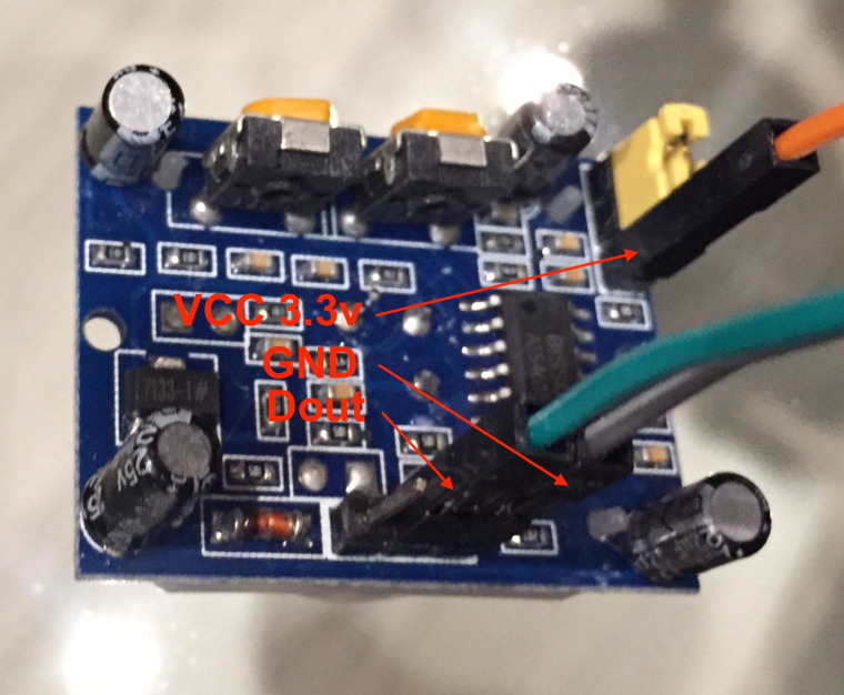
I planned to use the one with photoresistor:

But it appears to be quite power greedy. There are 2 LEDs onboard: power and threshold. I've made some measurements:
2 LEDs on: 3.7 mA
1 LED on: 2.3 mA
Both LEDs removed: 1.1 mAThat's way too high for battery powered node. What I want to build is the node with movement, light (on/off), temperature and humidity sensors. For the moment this light module is the showstopper for my node.
I also have BH1750FVI GY-302 one which good power budget, but it's not able to produce pin change signal to wake my node up on when light is on or off.
Just ordered APDS-9930 which seems to have INT pin which can be configured to rise by threshold, but maybe somebody know the better solution? -
you can also find OPT3001 boards at aliexpress if i'm not wrong. Maybe a bit more expensive than MAX at ali, but you can get the INT pin (you'll need to remove the regulator if there is one onboard, for low power).
It will be more efficient than APDS ;)MAX and OPT300x are almost equal for low power, not a big diff, except the lux range but i use it for indoor (so i'll never reach >100 000lux!). I use OPT3001 because it's cheaper at mouser in quantity.
-
Thanks for your suggestions! I'll give them a try. At least now I know that's indeed doable
-
Or a photoresistor and a transistor?
-
Why not just an LDR voltage divider. 2 components. Look at this:
https://learn.adafruit.com/photocells/using-a-photocell -
Hm, let me try. I just think photoresistor will consume quite a lot of power just by itself. But let me try
-
Hello,
I bought OPT3001 here :
https://www.aliexpress.com/item/High-Quality-CJMCU-3001-OPT3001-ambient-light-sensor-to-the-human-eye-as-a-single-chip/32672773503.html?spm=2114.13010608.0.0.UGMh7iAnd MAX44009 breakout board (GY-49) here :
https://www.aliexpress.com/item/GY49-MAX44009-Ambient-Light-Sensor-Module-for-Arduino-with-4P-Pin-Header-Module/32772767521.htmlBoth have interrupt pin broken out, it's just on the opposite side for the MAX44009 board (next to "49" text) instead of inline with other pins like for OPT3001.
MAX44009 is much cheaper as a breakout board, and after removing the regulator (I run it on button cell) the power consumption is just insanely low, I can't even see the difference with my multimeter when it's connected to the board or not.
I have not tested the OPT3001 yet but I don't expect much more power consumption after removing regulator.
If you keep the regulator you should stay below 10µA with the 2 boards, I don't believe you can get that low with a photoresistor. -
Yes, I also just love I2C sensors, thus prefer them against other due to power and pins consumption.
BTW tried to run my test node without light sensor (while waiting for them to be tested) and found results quite frustrated: it appears that PIR sensor generates a lot of false positives (~ each min). For PIR I use HC-SR501 which connected to 3.3v directly like:
-
Yes, I also just love I2C sensors, thus prefer them against other due to power and pins consumption.
BTW tried to run my test node without light sensor (while waiting for them to be tested) and found results quite frustrated: it appears that PIR sensor generates a lot of false positives (~ each min). For PIR I use HC-SR501 which connected to 3.3v directly like:
@Vladimir-Dobrikov If you are getting false positives, it could be because of your input voltage. You are only supplying 3.3 volts which is too low. The operating voltage of these is 4.5 - 20 volts.
-
Hm, let me try. I just think photoresistor will consume quite a lot of power just by itself. But let me try
@Vladimir-Dobrikov Using a 10K pull-down resistor at full brightness using 3.3volts you are going to consume somewhere around 0.3mA, which is going to probably be your highest consumption. On a dark moonlit night you are only consume around 41 uA. I wouldn't think that should be too bad. Unless I calculated something wrong, that should last a while.
-
@dbemowsk for the moment I don't use any light sensor (still waiting for delivery). As for PIR, I've connected it a bit unregular way. When I test it with serial connection, it works pretty stable and predictable way even with 3.3v.
-
Made some measurements with current config:
Sending data: 0.54 mA
Sleep (motion on): 0.16 mA
Sleep (motion off): 0.09 mAWiring:
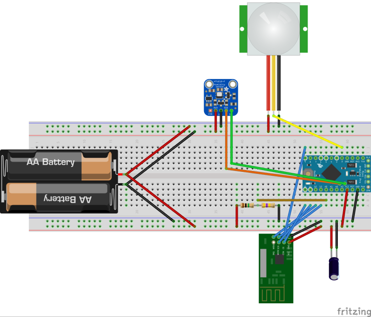
Sketch:
/* * Multisensor MySensors node (temperature, humidity, light, motion) * * MCU: * - Arduino Mini 3.3v * * Integration type: * - MySensors (Radio NRF24) * * MySensors version: * 2.1.0 * * Modules: * - nRF24L01: radio * - HTU21 / GY-21: temperature/humidity * - TBD: light * - HC-SR501: motion * * Wiring: * Arduino nRF24L01 * 9 <------> CE * 10 <------> CSN/CS * 13 <------> SCK * 11 <------> MOSI * 12 <------> MISO * N/C <------> IRQ (not connected) * * Arduino HTU21 * A4 <-----> SCL * A5 <-----> SDA * * Arduino Light (TBD) * * Arduino HC-SR501 * 2 <------> Dout * * Author: * Vladimir Dobrikov <hedin.mail@gmail.com> */ // Enable debug prints // #define MY_DEBUG #define SKETCH_NAME "temp-hum-light-movement" #define SKETCH_VERSION "1.1" // Enable and select radio type attached #define MY_RADIO_NRF24 #define MY_RF24_PA_LEVEL RF24_PA_MIN // RF24_PA_MIN, RF24_PA_LOW, RF24_PA_HIGH, RF24_PA_MAX //#define MY_NODE_ID 10 // Keep MySensors.h below config definitions #include <Arduino.h> #include <MySensors.h> #include <SparkFunHTU21D.h> #define THRESHOLD_TEMP 2 // threshold to send update #define THRESHOLD_HUMD 2 // threshold to send update const unsigned long INIT_PIR_TIMEOUT_SEC = 5; // 3 sec to init PIR after poweron const unsigned long SLEEP_TIME_MIN = 15; // Sleep time between reports (in milliseconds) const byte BATT_WAKEUPS_MAX = 100; // Max wakeup times to send battery status const byte ENV_WAKEUPS_MAX = 10; // Max wakeup times to send temp/humidity status // #define DEBUG_OUPUT #if defined(DEBUG_OUPUT) #define DBGPRINT(str) Serial.print(str) #define DBGPRINTLN(str) Serial.println(str) #else #define DBGPRINT(str) #define DBGPRINTLN(str) #endif // Only 2 and 3 generates interrupt! #define PIN_MOTION 2 #define PIN_LIGHT 3 #define PIN_BATT A0 // Child nodes IDs #define CHILD_ID_MOTION 1 #define CHILD_ID_LIGHT 2 #define CHILD_ID_TEMP 3 #define CHILD_ID_HUMD 4 // Initialize messages MyMessage msgMotion(CHILD_ID_MOTION, V_TRIPPED); MyMessage msgLight(CHILD_ID_LIGHT, V_TRIPPED); MyMessage msgTemp(CHILD_ID_TEMP, V_TEMP); MyMessage msgHumd(CHILD_ID_HUMD, V_HUM); HTU21D sensorTempHumd; int8_t wakeupReason = -42; // Is there any convenient tool lib for that? bool prevMotion = false; bool motion = false; bool prevLight = false; bool light = false; float prevHumd = 0; float humd = 0; float prevTemp = 0; float temp = 0; int prevBattPcnt = 0; int battPcnt = 0; byte battWakeups = 0; byte envWakeups = 0; void setup() { analogReference(INTERNAL); // For batt measurement pinMode(PIN_MOTION, INPUT); pinMode(PIN_LIGHT, INPUT); sensorTempHumd.begin(); sensorTempHumd.setResolution(USER_REGISTER_RESOLUTION_RH10_TEMP13); DBGPRINTLN(F("Sleep till PIR init")); sleep(INIT_PIR_TIMEOUT_SEC * 1000); } void presentation() { // Send the sketch version information to the gateway and Controller sendSketchInfo(SKETCH_NAME, SKETCH_VERSION); // Register all sensors to gw (they will be created as child devices) present(CHILD_ID_MOTION, S_MOTION); present(CHILD_ID_LIGHT, S_CUSTOM); present(CHILD_ID_TEMP, S_TEMP); present(CHILD_ID_HUMD, S_HUM); } void loop() { // negative: timeout // 0: 1st interrupt // 1: 2nd interrupt DBGPRINTLN(F("---------------------------")); DBGPRINT(F("wakeupReason = "));DBGPRINTLN(wakeupReason < 0 ? "timeout" : wakeupReason == 0 ? "motion" : wakeupReason == 1 ? "light" : "unknown"); battWakeups = battWakeups >= BATT_WAKEUPS_MAX ? 0 : battWakeups + 1; DBGPRINT(F("battWakeups = "));DBGPRINTLN(battWakeups); envWakeups = envWakeups >= ENV_WAKEUPS_MAX ? 0 : envWakeups + 1; DBGPRINT(F("envWakeups = "));DBGPRINTLN(envWakeups); if (battWakeups == 0) { battPcnt = getBattPcnt(); DBGPRINT(F("battPcnt = "));DBGPRINTLN(battPcnt); } motion = digitalRead(PIN_MOTION) == HIGH; DBGPRINT(F("motion = "));DBGPRINTLN(motion); light = digitalRead(PIN_LIGHT) == LOW; // Reverse logic DBGPRINT(F("light = "));DBGPRINTLN(light); if (envWakeups == 0 || wakeupReason < 0) { humd = sensorTempHumd.readHumidity(); DBGPRINT(F("humd = "));DBGPRINTLN(humd); humd = roundFloat(humd); temp = sensorTempHumd.readTemperature(); DBGPRINT(F("temp = "));DBGPRINTLN(temp); temp = roundFloat(temp); } // Keep send action in the bottom close to each other to wakeup radio only // if needed and have it awake minimum time sendDataIfUpdate(); // Sleep until interrupt comes in on motion or light sensor or sleep timeout. DBGPRINT(F("Going to sleep for (min): "));DBGPRINTLN(SLEEP_TIME_MIN); wakeupReason = sleep(digitalPinToInterrupt(PIN_MOTION), CHANGE, digitalPinToInterrupt(PIN_LIGHT), CHANGE, SLEEP_TIME_MIN * 60 * 1000); } void sendDataIfUpdate() { if (prevBattPcnt != battPcnt) { prevBattPcnt = battPcnt; DBGPRINT(F(" Sending batt: "));DBGPRINTLN(battPcnt); sendBatteryLevel(battPcnt); } if (prevMotion != motion) { prevMotion = motion; DBGPRINT(F(" Sending motion: "));DBGPRINTLN(motion); send(msgMotion.set(motion)); } if (prevLight != light) { prevLight = light; DBGPRINT(F(" Sending light: "));DBGPRINTLN(light); send(msgLight.set(light)); } if (abs(prevHumd - humd) >= THRESHOLD_HUMD) { prevHumd = humd; DBGPRINT(F(" Sending humd: "));DBGPRINTLN(humd); send(msgHumd.set(humd, 1)); // 1 means number of digits of fractional part } if (abs(prevTemp - temp) >= THRESHOLD_TEMP) { prevTemp = temp; DBGPRINT(F(" Sending temp: "));DBGPRINTLN(temp); send(msgTemp.set(temp, 1)); // 1 means number of digits of fractional part } } int getBattPcnt() { int rawBattVal = analogRead(PIN_BATT); DBGPRINT(F("rawBattVal = "));DBGPRINTLN(rawBattVal); return rawBattVal / 10; } // Round to 0.5 float roundFloat(float val) { return round(val * 2) / 2; } -
Does anybody know any low power light sensor which can produce pin change interrupt for Arduino?
I planned to use the one with photoresistor:
But it appears to be quite power greedy. There are 2 LEDs onboard: power and threshold. I've made some measurements:
2 LEDs on: 3.7 mA
1 LED on: 2.3 mA
Both LEDs removed: 1.1 mAThat's way too high for battery powered node. What I want to build is the node with movement, light (on/off), temperature and humidity sensors. For the moment this light module is the showstopper for my node.
I also have BH1750FVI GY-302 one which good power budget, but it's not able to produce pin change signal to wake my node up on when light is on or off.
Just ordered APDS-9930 which seems to have INT pin which can be configured to rise by threshold, but maybe somebody know the better solution?A simple solution you can use is to power the LDR Sensor board (shown) from an output pin on the Arduino, turning the pin/power on briefly while you take a light sample. (An arduino pin can drive 20ma safely from memory).
For example, if you sample the light level for 10ms (0.01 sec), every 10 seconds (or 1 sec etc), your average power requirements (for the light sensor) will drop from 1.1ma to 0.00011 if I've done my maths right.
This is assuming you don't need to 'instantly' know every little change in light level. If you are recording general ambient light levels, having an interrupt for every minor change could generate excessive interrupts and data transmissions, consuming heaps of power for the RF transmission.
In my system, I measure ambient light with a 10 cent LDR and resistor, and UV levels with a UV sensor. I started sampling every 10 seconds during initial tests, but now I only wake the Arduino once a minute, take a sample and ONLY transmit data if either has changed or 15 minutes has passed.
By doing this, my light sensor module has been running 18 months with a small lithium battery, charged by a small solar panel. I checked it a few weeks ago and found the solar cell covered in cob-webs and dust etc, but it was still charging fine.
I would strongly suggest you check out https://github.com/mysensors/NodeManager as it will give you the following benefits:
- Has templates for LDR, Temp, Hum & Motion sensors.
- Looks after power management sleeping the Arduino
- Can manage turning your LDR on/off as required.
- Report current battery level.
Regards,
Paul
-
@Vladimir-Dobrikov If you are getting false positives, it could be because of your input voltage. You are only supplying 3.3 volts which is too low. The operating voltage of these is 4.5 - 20 volts.
Hello @dbemowsk
I don't have the specs in front of me at the moment, but the versions of this device I have (with circuit diagram) look the same and operate internally on 3.3v and have an LDO 3v3 regulator, enabling them to run off 5v+. I think you can see it it the large picture, under letters VCC (in red), it's marked "7133-1#". @Vladimir-Dobrikov is correctly powering it by providing 3.3V to pin 3 of jumper block 1, this bypasses the regulator, providing your 3.3v direct to the circuitry (on mine at least).Refer: http://www.electrodragon.com/w/PIR_sensor#PIR_sensor_Schematic
The wiring @Vladimir-Dobrikov used looks the same as mine, i.e. the jumper and power to the pin in the upper right of the photo.
In my case, I use them to turn on several different room lights when someone enters and have not noticed any false triggers once I adjusted the sensitivity down a bit. Great value and low power - fantastic devices!!!
Paul
-
Yes, I also just love I2C sensors, thus prefer them against other due to power and pins consumption.
BTW tried to run my test node without light sensor (while waiting for them to be tested) and found results quite frustrated: it appears that PIR sensor generates a lot of false positives (~ each min). For PIR I use HC-SR501 which connected to 3.3v directly like:
Have you adjusted the sensitivity? All of mine (10) arrived set to almost maximum sensitivity and I had false triggers in an empty room, however once I adjusted the sensitivity a low as I could, yet detect a person, they have been 100% reliable.
NOTE: These devices need to warm up, so I recommend leaving them powered up for 30 minutes before you attempt to adjust them.
Hope that helps,
Paul
-
@AffordableTech, regarding PIR sensors, I've got an advice to add 3rd battery since this sensor is very sensible to VCC level and under 3v isn't predictable. So I've connected batteries as suggested here:
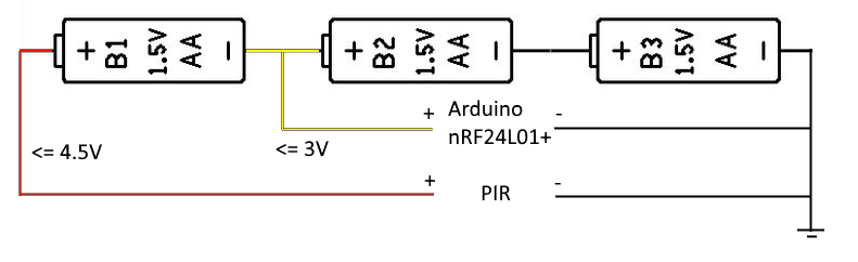
I also thought about step-up convertor to power PIR with exactly 3.3v, but I was said this kind of power line is quite noisy which again will cause false positives so Ive rejected this option.With this setup (3AA) my node became reliable and works that way about 1 week.
As for light sensor, after some thoughts I came into decision to use BH1750FVI sensor which is also I2C one with low consumption if configure it with one time measurement mode (by default it's continuous mode).
My use case is to trigger light by motion only if light level is 0. Now I just send light level alongside with motion event, thus no need of waking up by light interrupt anymore.
Hello! It looks like you're interested in this conversation, but you don't have an account yet.
Getting fed up of having to scroll through the same posts each visit? When you register for an account, you'll always come back to exactly where you were before, and choose to be notified of new replies (either via email, or push notification). You'll also be able to save bookmarks and upvote posts to show your appreciation to other community members.
With your input, this post could be even better 💗
Register Login