CNC PCB milling
-
@rfm69 Almost always just PCBs. Maybe sometimes some acrylic, but nothing very solid, if that's what you're asking. Those little 1610 CNCs have so many plastic parts, that I'm not sure it'd perform very well cutting anything much harder than plastic.
-
@neverdie Yes; brushless motors are for sure more technically complex than brushed, and usually require an external driver. Most of the time those drivers have inputs allowing you to control the speed via PWM or an analog voltage.
Adapting the 1610's woodpecker board to supply that PWM speed control signal to an external driver is super easy -- I can show you a photo of what I did to mine if it'd help.
-
@neverdie said in CNC PCB milling:
@executivul
Do you suppose that linear rails, rather than supported rods, would fix this twisting problem that people seem to be having?i.e. Notionally, something like:
https://www.ebay.com/itm/Portable-Steel-MGN12H-Linear-Sliding-Rail-Block-Tool-250-550mm-CNC-3D-Printer/382360155951?var=651145928342&hash=item590670f72f mah05n6MWl2QkZTLIZW2vJQ
that's made out of steel.Yes, but MGN15 or larger and of better quality, but that is expensive...
-
@executivul
I guess the difficulty of finding a satisfying solution to this problem explains why milling machines are built around a stationary, highly rigid z-axis.
-
@neverdie And finding a good tool at an affordable price is a challenge. Specialised machines do a s specific job better than general purpose ones, but only do that job. Professional machines do a better job at a higher price tag. We are just poor hobbyists

I'm so happy with my $50 UT61E, what a great multimeter, of course I would rather have a HP 8.5 digit one any day but I'd rather spend that money on a holiday or something since I don't need that 0.0001uV precision anyway, at 1V a 3V bat is as empty as a 0.9999999987V one if you get my point. Too many times I've spent a fortune for professional tools which I don't use/need so I tend to get what I need + a small margin, for eg I got a huge DSLR and lenses, used a few times, great photos, but lately, guess what, I tend to use my phone for taking photos 99.9% of the time, the camera backpack is just too heavy to carry arround .
Get a 3d printer, get a 3040/6040 cnc, get a 40/50W laser, get a lathe if you have space for it, maybe get a vertical mill for metal parts and you'll have a maker space of your own, as long as you won't start manufacturing space ships ebay tool tolerances will be ok.
-
Reminds me of a quote from the MPCNC website (https://www.v1engineering.com/frequently-asked-questions/ ) :
Diminishing returns kicks in really fast in the CNC world.
-
I suppose, in theory, that somehow replacing the x and z-axis with these might mitigate against the twist problem:
Presumably the rails are precisely spaced and held perfectly flat by the base plate, so you'd avoid binding problems that might otherwise arise from a purely DIY manual retrofit of just the rails.
I don't know what the MGN number is for that rail though, so I don't know whether its MGN15, MGN20, or something else.
-
@neverdie said in CNC PCB milling:
@dbemowsk said in CNC PCB milling:
a dual notched pulley
I don't know what that is.
I wasn't sure of the exact name for it, but I was referring to something like this:
https://www.amazon.com/ReliaBot-Aluminum-Timing-Pulley-Printer/dp/B079JGYYKV/ref=sr_1_5?s=industrial&ie=UTF8&qid=1520378263&sr=1-5&keywords=dual+timing+pulley
-
@dbemowsk
I take back what I said earlier. I like the way this guy did it better, because with the gearing you can get even more resolution out of your encoder:
Converting a Stepper Motor to a Closed-loop Stepper Motor - Part 1 – 04:08
— Kris Temmerman
-
@neverdie I agree, that that may be better. To change the precision, you would just have to change the gear ratio of the two meshing gears.
-
I did some more reading about CNC'ing aluminum, and it's being claimed that virtually any CNC machine can cut aluminum, provided it uses the right depth of cut and speeds and feeds. i.e. it may simply take a lot longer than you would prefer if your machine isn't already super rigid. If that's true, I can probably live with that.
Meanwhile, it has been suggested that using PID might improve things. There's SuperPID for AC powered spindles and I'm not sure what for DC powered spindles. Regardless, I'll need to sense the RPM of the spindle, or it won't work, so that's now on the critical path. I think I'll try a spinning magnet and a hall sensor to sense the RPM.
-
@coddingtonbear said in CNC PCB milling:
@NeverDie -- the motors used in 1610 CNC mills are generally what are called a "775 Motor". You might be able to find other specs, but the ones I've found suggest that at 24V and no load , they claim 7kRPM -- http://linksprite.com/wiki/index.php5?title=File:Motor_performance_parameter.png; I'm not sure how much slower we could expect it to be while milling. As far as actually measuring this, there are devices you could buy, but you could pretty easily fabricobble your way to an answer if you wanted to make a project out of it: http://www.instructables.com/id/Measure-RPM-DIY-Portable-Digital-Tachometer/.
I have the same mill as you, and swapped for one of these https://www.amazon.com/gp/product/B074FVKRZM/ and have had much better results so far.
Does the controller that comes with your motor allow you to set the RPM of the motor, or does it just set the voltage? If it knows RPM and can act like a PID (i.e. adapts to maintain the target RPM even under varying loads), then it would be very attractive.
-
I went ahead and orderd the Hall Effect version, which appears to come with some kind of DSP PID controller to control the speed of its DC spindle.
https://www.aliexpress.com/item/Freeshipping-Brushless-spindle-motor-driver-Motor-base-kit-BL-Engraver-Spindle-Motor-24VDC-60VDC-12000RPM-ER8/32849306845.html?spm=2114.search0204.3.72.2cc61acfYE6xkB&ws_ab_test=searchweb0_0,searchweb201602_5_10152_5711320_10151_10065_10344_10068_10130_10324_10342_10547_10325_10343_10546_10340_10548_10341_10545_10084_10083_10618_10307_5711220_5722420_10313_10059_10534_100031_10103_10627_10626_10624_10623_10622_10621_10620,searchweb201603_25,ppcSwitch_5_ppcChannel&algo_expid=7790ac4f-6dbd-47b4-9574-1d713348386c-11&algo_pvid=7790ac4f-6dbd-47b4-9574-1d713348386c&transAbTest=ae803_3&priceBeautifyAB=0
-
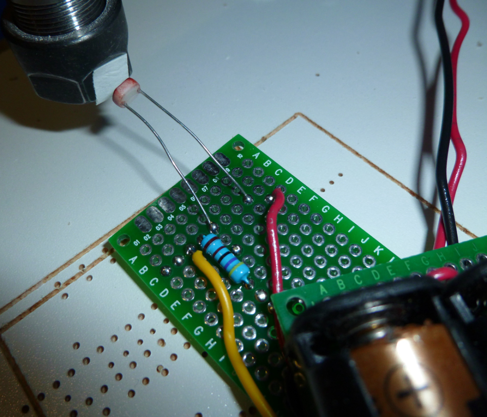
I used a piece of white tape, a photo resistor, and an oscilliscope to measure the RPM on the existing spindle that came with the 2418 kit. Unloaded, it's 8333RPM.
-
I did further tests on my CNC this morning, with interesting results.
First, I confirmed that the motor is, indeed, being powered at 24VDC using pulse width modulation from the WoodPecker. As an experiment, I tried powering it directly from my lab bench power supply at different voltages, and it definitely runs smoother that way rather than relying on PWM.
Second, when I ran it at very low speeds, I could tell visually that the spindle runout was attrocious. I think this is a big contributing factor to vibration, audible noise, and probably tearing in the copper of the PCB. It may be that the large stick-out of the ER11 is a contributing factor.
-
I have a question regarding setup of the CNC. Which directions are the positive directions for all of the axes? For example, if I send "Z10" should the spindle move up or down?
X - left or right?
Y - forward or backward?
Z - Up or down?
-
@dbemowsk
X: right
Y: forward
Z: up
-
@neverdie Yes, it does. There are a variety of ways of controlling the one I bought, and you can easily configure which method is in use. I think this one has three different options -- controlling RPM via an analog voltage, controlling RPM via PWM, and controlling RPM via a knob on the controller. I use PWM, but you'll probably always want to be at full speed when milling PCBs, so I'd bet just using the knob would be fine.
-
@neverdie Congratulations on your purchase! I think you'll find having a real spindle will help a ton.
If you haven't designed your own mount, you might want to check out the part I posted on Thingiverse the other day: https://www.thingiverse.com/thing:2817974 .
-
@coddingtonbear said in CNC PCB milling:
@neverdie Yes, it does. There are a variety of ways of controlling the one I bought, and you can easily configure which method is in use. I think this one has three different options -- controlling RPM via an analog voltage, controlling RPM via PWM, and controlling RPM via a knob on the controller. I use PWM, but you'll probably always want to be at full speed when milling PCBs, so I'd bet just using the knob would be fine.
So, during deeper cuts, the controller responds by giving the spindle more oomph to maintain the specific RPM you set? That's the key question.
-
@coddingtonbear said in CNC PCB milling:
@neverdie Congratulations on your purchase! I think you'll find having a real spindle will help a ton.
If you haven't designed your own mount, you might want to check out the part I posted on Thingiverse the other day: https://www.thingiverse.com/thing:2817974 .
Thanks! That does increase the cantilever effect, but it's a good start. I guess it's even good enough based on your experience so far, which would be awesome. Thanks for sharing.
-
@neverdie Hrm; honestly I haven't monitored it very closely, and almost always run the spindle at full speed; so I can't really say for sure if it would attempt to adjust to make up for higher friction. Also, I have the NVBDL rather than the NVBDH version, so I'm not even sure if it is able to tell if the motor is spinning slower than intended.
If either of us have a chance of that being a possibility, it's probably you with the slightly better spindle driver.
-
@coddingtonbear Makes sense. I should be able to trap the signal from the hall effect encoder to confirm the RPM using an Arduino, and then I can compare actual against prescribed RPM to see how well they match. But, as you say, it may not matter if the best speed for etching PCB's is simply "as fast as possible." i.e. if 'it's already running at maximum voltage, then there's no headroom left to speed up an overloaded bit.
-
I ordered a 3.175mm ER8 collet for the new spindle so that I can continue using my same bits:
-
The NVBDH+ brushless spindle and controller arrived today, and so I hooked them up to a power supply and gave them a quick test spin. It runs comparatively quiet. The motor itself is pretty much sealed. On the positive side of that, little if any dust will ever get inside it. On (maybe) the negative side, the fan basically directs air at the back of the motor, and not really anywhere else. I’m only guessing, but keeping other parts of it cool may prove challenging if doing a lot of deep cuts on wood, for example.. For milling PCB’s, I don’t think it will be a problem though. It has little, if any, visible run-out, so in that dimension it appears to be far better than the spindle that came with the 2418 kit.

I won't be able to test it on the CNC itself until after my 3D printer arrives because it's too large to fit the kit spindle's holding bracket.
-
@coddingtonbear How hot does your motor get when you're using it? I'm concerned that only one end of it seems to be getting blown by the fan, and since it will be held by plastic....
-
Perhaps it would be possible to buy a water cooling jacket for the spindle? That would cover the bases against even heavy duty use. Notionally, something like: https://www.aliexpress.com/item/1Pcs-Hobbywing-SEAKING-Water-Cooling-Jacket-Water-Cooled-Tube-Cover-for-Motor-2040-2848-3660-Tube/32824602383.html?spm=2114.10010108.1000015.2.1e5d6295V0eV3w
Alternately, I notice an inexpensive brushless motor with a water cooling jacket already installed, for not much money:
https://www.aliexpress.com/item/B2040-4000KV-3000KV-Inrunner-Water-Cooled-Brushless-Motor-For-Rc-Boat/32713150282.html?spm=2114.10010108.1000015.6.1e5d6295V0eV3w
It could also go up to around 48,000RPM at 12v. The main downside to that is that it would require installing an ER11 collet, and so runout might be an issue.Or, just get this, which goes to 24,000RPM and has water cooling already a part of it:
https://www.aliexpress.com/item/CNC-65MM-ER11-1-5KW-WATER-COOLED-MOTOR-SPINDLE-AND-DRIVE-INVERTER-VFD/32721276915.html?spm=2114.search0104.3.1.6558afa34wxhfY&ws_ab_test=searchweb0_0,searchweb201602_5_10152_10151_10065_10344_10068_10130_10324_10342_10547_10325_10343_10546_10340_10548_10341_10545_10696_10084_10083_10618_10307_5711212_10313_10059_10534_100031_10103_10624_10623_10622_10621_10620_10810_10811_5722415_5711312,searchweb201603_25,ppcSwitch_5&algo_expid=9b150460-dd19-4ed5-bba5-dea1262c58d2-0&algo_pvid=9b150460-dd19-4ed5-bba5-dea1262c58d2&transAbTest=ae803_5&priceBeautifyAB=0
-
I found a very similar motor being used on a thingiverse printed CNC machine: https://www.thingiverse.com/thing:1001437 and also: https://www.thingiverse.com/thing:1750276 . That's giving me more confidence that the heat will be manageable.
-
Epilog: I ran the brushless spindle unloaded continuously at its maximum speed and monitored its temperature using a DS18b20 temperature sensor beneath the holding bracket (so, getting the least amount of circulated air onto it). It reached an equilibrium temperature of around 31C. Also, it turns out that it actually does have pretty good air flow. So, I’m no longer worried about this spindle getting too hot.

-
UPDATE: I received and installed a pair of chromed hardened steel rods onto the x-axis. Wow! I could feel an immediate improvement in rigidity. I wasn't really expecting that, so it made me curious. I tested the new rails with a magnet: yes, they attract a magnet. Then I tested the old rails with a magnet. No attraction! Therefore, I think maybe the old rails are probably aluminum. Aaaargh! That would explain a lot. So, FYI for anyone else who buys one of these Chinese kits.
-
Yup, I just now did a spark test on the old rods, and the result is conclusive: definitely aluminum. I should probably replace the z-axis rails as well.
-
Epilog: Definitely much less vibration in the CNC now that the x-axis rods have been replaced with steel rods. I've ordered y-axis and z-axis steel rods, so I plan to replace those as well. Hopefully doing so will damp the vibration even further.
-
I just now ran across z-axis tape, which may prove to be a God send for using any of the 6mil isolation routed PCB's that I might make on this PCB etcher. The problem I was having with such isolation routed boards was: no solder mask! So, soldering parts to the boards just wasn't working for me, and I had fallen back to producing boards with much larger isolation widths. However, it appears that with 3M's z-axis tape, I can just tape the SMD parts down onto the board, with no soldering required!
Amazing! From my perspective, it's downright revolutionary:
https://www.adafruit.com/product/1656
-
@neverdie Interesting stuff! I didn't know it existed.
I saw a sparkfun youtube video in which they use it to tape down an ATMega TQFP instead of soldering it, but they keep it pressed down during the demo.
So, do you think it can also be used to mount chips?
-
@yveaux said in CNC PCB milling:
So, do you think it can also be used to mount chips?
Yes! One of my favorite youtubers shows it being done at time index 1:00 on:
Part 2: Hi-Res Pressure Sensor Matrix Mat finished – 09:37
— Marco Reps
-
Anyone know whether it is possible to etch some or all of the silkscreen onto the PCB? I've tried some googling, and I haven't found any leads on how to do it using flatcam.
-
-
@neverdie What about using toner transfer paper and ironing it on. Just print it reversed on a sheet, cut it out and iron it on. If you use a color laser you could do something other than black. Obviously you won't get white like a lot of fabs use, but I would think it would be good enough.
-
@executivul said in CNC PCB milling:
@neverdie http://caram.cl/software/flatcam/tracing-the-silkscreen-with-flatcam/
Have you tried it? i.e. Do you know if it works, or is it a blind reference?
-
Here's a very impressive looking demo of PCB etching:
https://www.youtube.com/watch?v=cwE3FqRb8ZgI checked the machine specs, and it's a maximum of 11,000RPM on a brushless spindle . That's very encouraging.
-
@neverdie I never used it to do silkscreening, but years ago I made a few PCBs to try a sheet out. It worked okay. I had some gaps in some traces on some the boards. That may have been from me not cleaning the board well enough before doing the transfer.
-
@dbemowsk Since the etching has to work (else there will be no PCB), I'd rather keep it within that domain if possible. Wegstr's lettering (above) looks very nice.
-
@neverdie said in CNC PCB milling:
@executivul said in CNC PCB milling:
@neverdie http://caram.cl/software/flatcam/tracing-the-silkscreen-with-flatcam/
Have you tried it? i.e. Do you know if it works, or is it a blind reference?
I've done it a few times, be careful though you don't cut your traces with the silkscreen

I use the tracing option all the time for custom cutouts when panelising boards, generate cutout paths in Altium and trace in Flatcam.
-
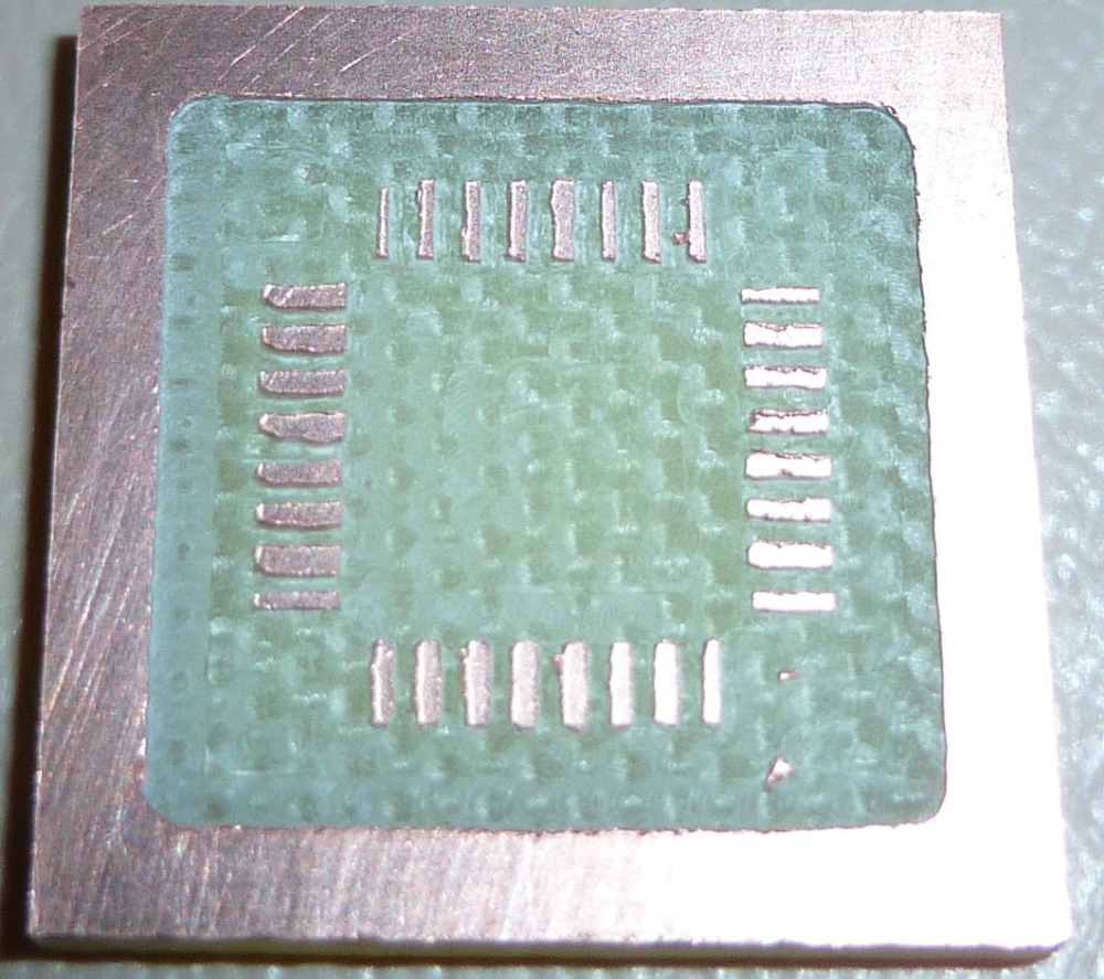
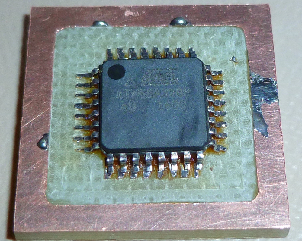
My Prusa i3 Mk3 still hasn't shipped due to production delays, and so I haven't been able to mount the new spindle yet on my PCB etching mill. Meanwhile, it looks as though the existing setup may just barely be good enough for etching pads for the atmega328p SMD. By using lots of rosin flux, it looks like I can solder to it without unresolvable solder bridges.
-
Also, I received a TMC2130 stepper driver, so I'll be auditioning that fairly soon:
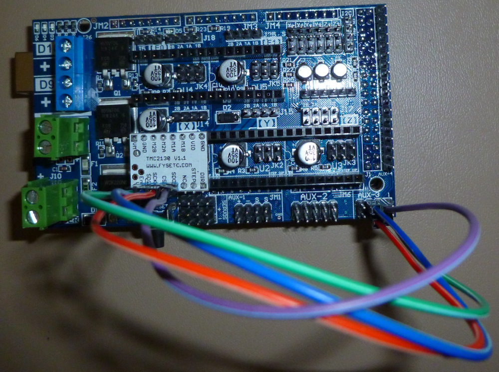
Supposedly it is a bit more precise, and so that may help also. If it pans out, then I'll order TMC2130's for the Y and Z axis also.
-
@neverdie Here is an interesting approach that might work, but it requires etching.
Making PCB with 3D printer and permanent marker – 07:57
— Lamja Electronics
-
@dbemowsk Using a laser is another way:
Casually Laser-Exposing 0.2 mm PCB features on a 3D printer – 09:10
— Marco Reps
-
Good news! This guy has identified what may be the ultimate stepper motor driver for CNC:
Precision motion control: ODrive Servo? Trinamic Stepper? Chinese Hybrid? – 11:38
— Marco RepsAnd he says that by pairing it with your own mosfets, you can send up to 20amps to your stepper motor. Taken altogether, this sounds like a really good setup to me.

I assume that with this gear you can just tell the motor to go at maximum speed all the time and let it decide (through monitoring) what that speed should be. No more underperformance or endless tuning of parameters.
-
@coddingtonbear said in CNC PCB milling:
If you haven't designed your own mount, you might want to check out the part I posted on Thingiverse the other day: https://www.thingiverse.com/thing:2817974 .
I'm finally able to print this. Is 20% infill OK, or does it need to be completely solid?
-
@neverdie IMHO I wouldn't think you would need it completely solid. make sure your side walls are thick enough though. I would use 1mm or more for strength. That's just my opinion though.
-
I blithely printed the parts using PLA. Now I need to find a strong glue to weld the braces into place. Anyone know of a strong glue that works well with PLA?
-
@neverdie Answering my own question, it appears (according to this Hackaday article: https://hackaday.com/2018/02/07/locally-sourced-pla-adhesive/) that weldon #16 will do the business in terms of solvent welding PLA.
-
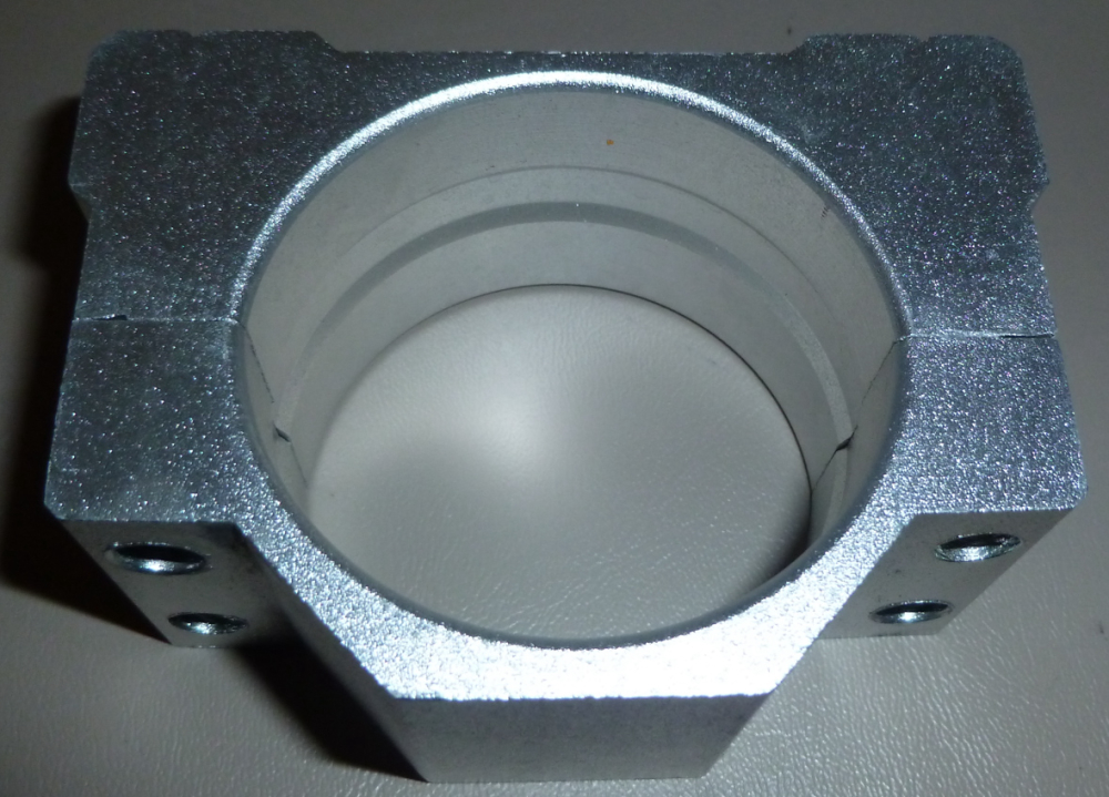
Comparing my spindle mount:
to Coddingtonbear's 55mm spindle mount:
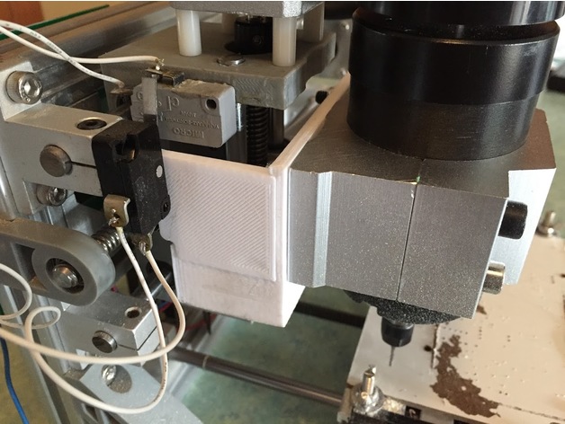
it seems that mine is intended for a 52mm spindle. Unfortunately, I'll just have to make do, as nobody that I can find seems to be selling standalone true 55mm spindle mounts, like Coddingtonbear has.Fortunately, though, the holes on mine do align with the holes on Coddingtonbear's 3D printed adapter.

-
I upgraded to the brushless motor after 3D printing cottingbear's adapter. Then I ran @executivul 's test scripts to check its performance. It looks as though the new spindel can support faster feedrates, but the trace isolation is 0.7mm, which is much larger than the original cheapo spindle.
 It has an ER8 on it, not an ER11. Not sure if that's to blame (?). I wouldn't think so, though, because I'm using a 1.75mm collet on it.
The z-axis still has a lot of flex in it. I think that's probably a factor. I'm not sure what can be done to mod my way out of that. Perhaps I'd be better off getting a proper CNC mill rather than this wobbly type of design.
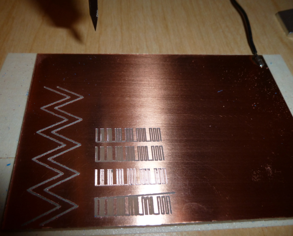
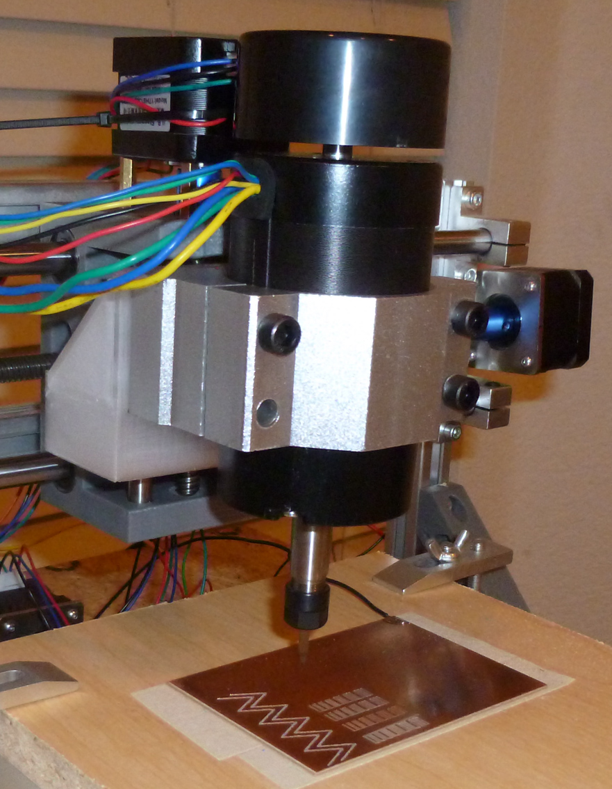
I can now see the advantage of having two z-axis motors, one on each side of the spindle. That would probably give it at least a bit more rigidity. Either that, or a single very rigid,, unmoving central column as used by mills.
-
Any suggestions on how to improve it?
-
@neverdie said in CNC PCB milling:
I can now see the advantage of having two z-axis motors, one on each side of the spindle.
Maybe just a stronger stepper motor.
-
I switched to a 52mm spindle, and now I'm getting better results:
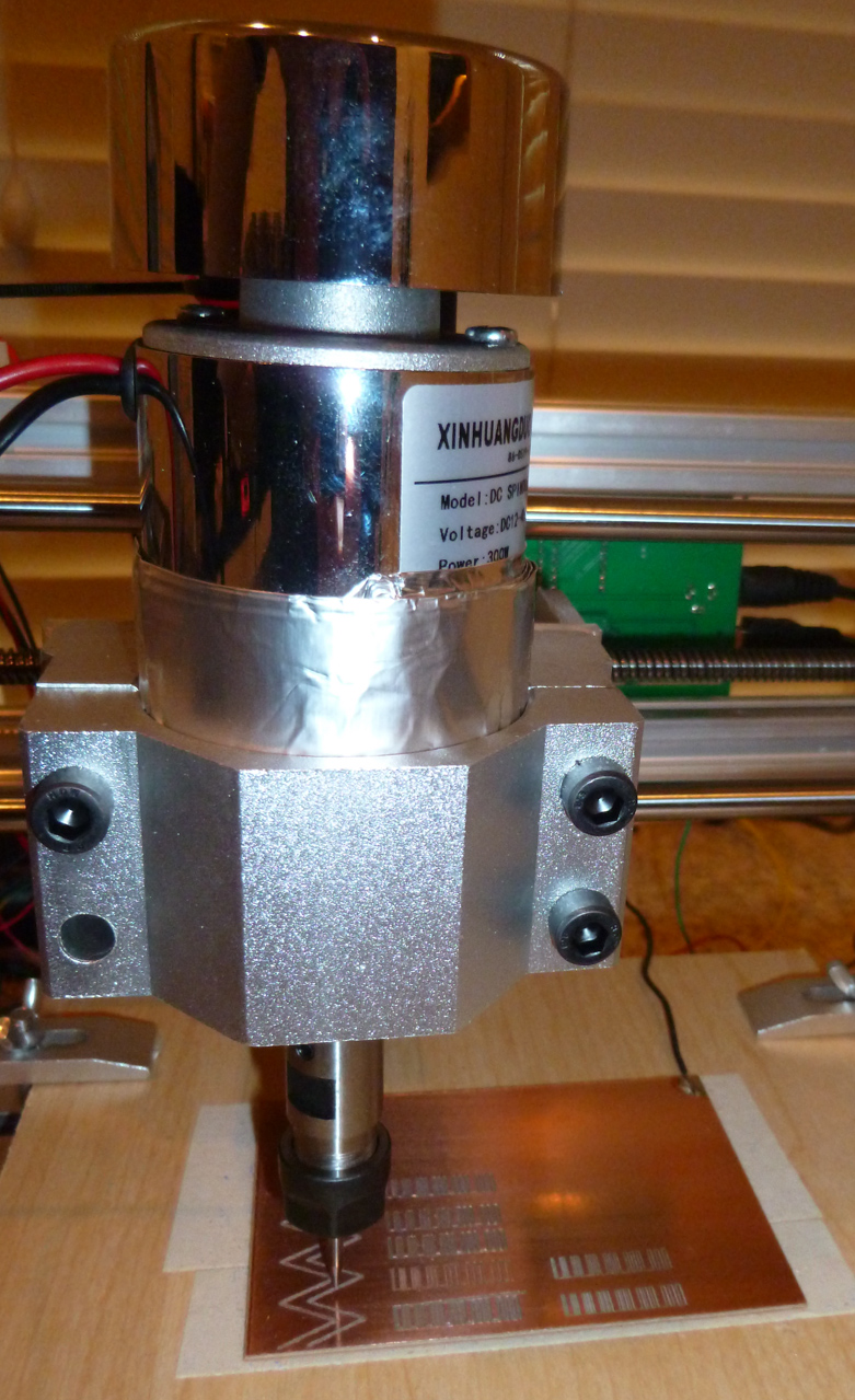
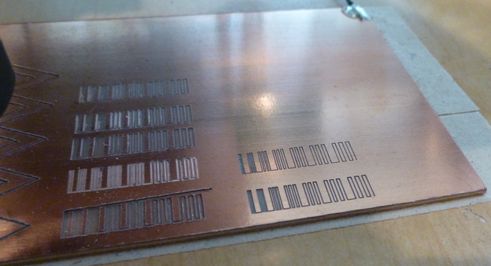
The benchmarks on the right were produced by the 52mm spindle. Those on the left by the 54mm brushless spindle.
-
@neverdie I guess some backlash being present. Is the brushless heavier than the other one?
The width of the cut is proportional to engraving bit tip size, depth of cut, tip angle, the spindle itself should be irrelevant except runout, of course, but you will hear the runout long before you see it, a 0.1mm of runout will make a hell lot of noise and rattling.
For greater rpms er8 is better than er11, my 60k rpm has er8 the 24k have er11.
Try to find the highers resonance pole rpm, turn the rpm to max, slowly decrease it while listening carefully, take a note when it's quieter, use the highest rpm that runs quietly. This setting unfortunately changes with every tool change, sometimes you won't have a good enough rpm resonant pole so you take out the bit, nut and collet and reassemble. By turning them you change the invisible runout a bit and you get another system state. On my spindle every 1/10-1/15 tool changes results in heavy resonance and I must proceed as above.
-
@executivul Cool! Here's my first attempt at that, and it's already producing a visibly different result:
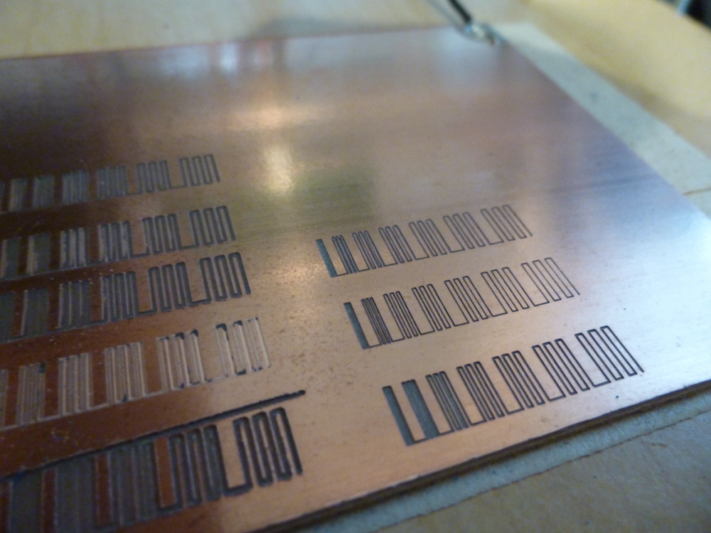
As to which spindle is heavier, I don't know. The next time I demount the brush spindle, I'll weigh it and let you know.
Thanks!
-
This guy developed his own method for balancing the high speed motors used on his quadcopter. I can't help but think that maybe something similar could be done on a CNC spindle.
In depth video how to balance brushless motors using a vibration meter and tape - Ontaerial – 25:35
— Yuri Retro
-
And these guys have the same idea, but they instead use a laser to visualize the magnitude of the vibration:
Flite Test - Laser Balancing Props - FLITE TIP – 07:11
— FliteTest
-
@neverdie knowing the vfd has a speed input I guess I could wire a simple arduino with a mic. Take note of the sound level and get it calibtared in no time, at the push of a button, but that project is far away, I have other things on my mind for the next few months.
-
hello everyone,
what is the current status with the quality, fine traces and result stability?
after a long absence I finally had some time to finish my new board and prototype it.
I don't have those issues that appearing for some of you, the result is pretty nice, the milling quality is the same across the whole board.
in this design the thinnest traces were 15mils, and the smallest vias were 0.8mm with 0.3mm drilled holes.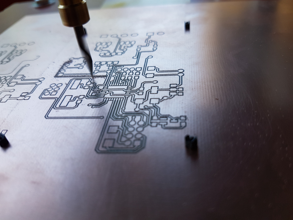
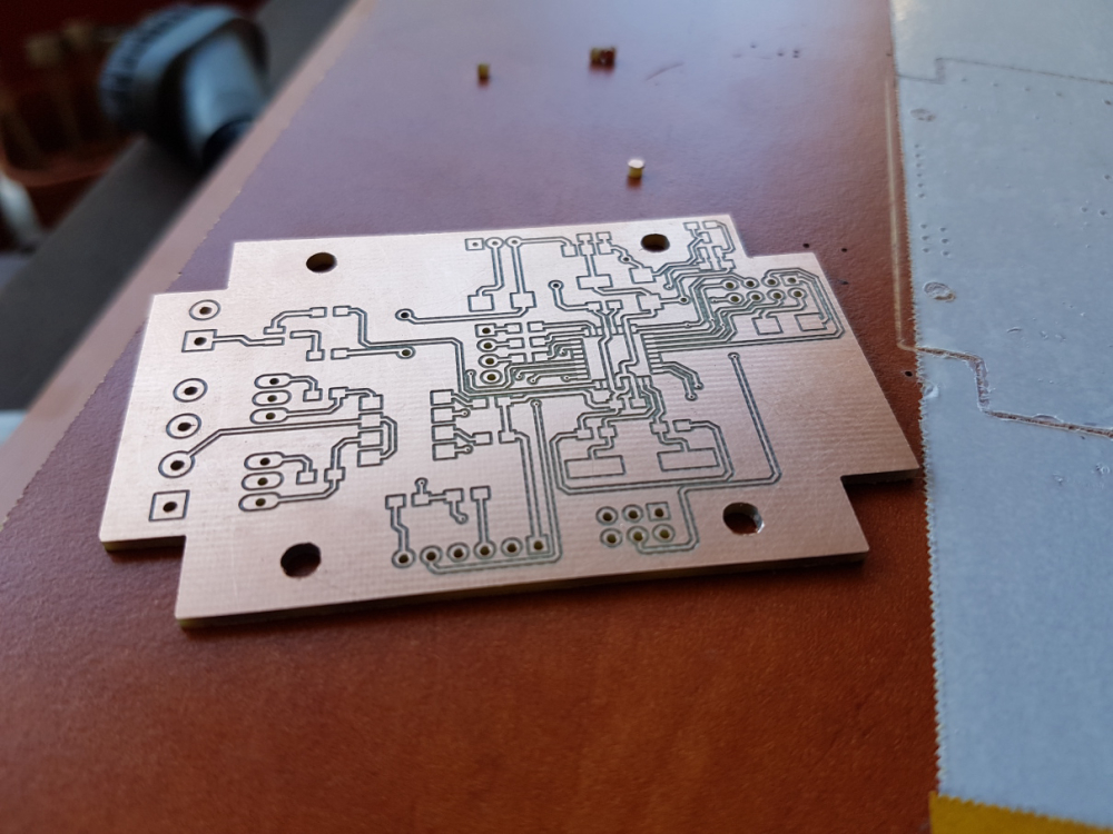
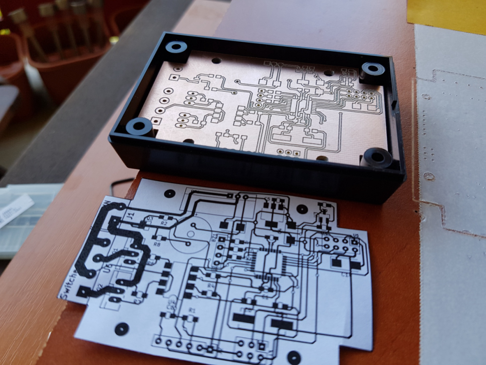
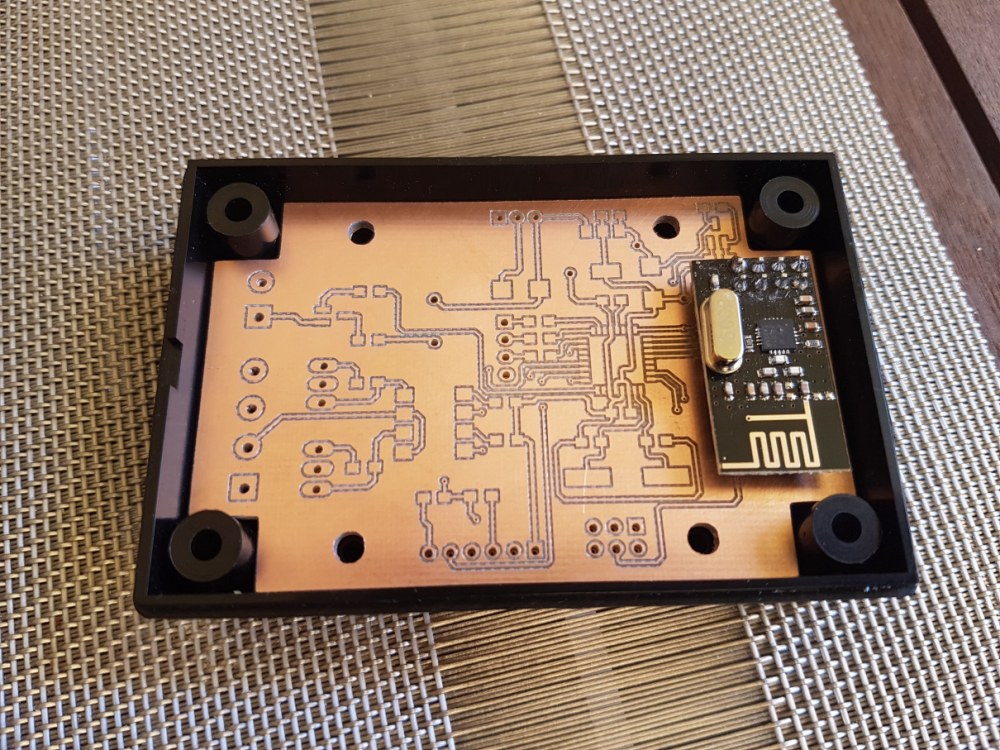
just for reference, please see my relevant configuration options detailed below:
tools
- cnc: cnc2418
- carving: 2001 bit (20 degree, 0.1mm end)
- mounting holes and outline milling: 0.8mm endmill
config
- isolation routing: tool dia: 0.1176326981mm; width (# passes): 2; pass overlap: 0.05mm; cut-z: -0.05mm; feed rate: 200
- milling: tool dia: 0.8mm; cut-z: -1.75mm; feed rate: 170; depth / pass: 0.3mm
- drilling: feed rate: 120
software:
- flatcam
- bcnc (also for the autoleveling)
-
Hi Andrew,
Since you ask about status, here's mine: I've now replaced all the aluminum smooth rods that came with my 2418 kit with chromed hardened steel ones which, it turned out, had about 0.04mm larger diameter. The result has been much less apparent vibration. I also upgraded the spindle to a higher rpm motor. I don't as yet have any quantified numbers to know whether the combination of doing all that has made any tangible improvement or not.
-
@andrew I ran @executivul 's diagnostic with my new setup:

Starting with 0.1mm, the trace width's increase by 0.1mm in each block.@executivul's g-code specified the feedrate at 1400.
So, yeah, 15mil looks like it would be achievable, even at that faster feedrate. On the otherhand, the woodpecker setting limits x and y to 200mm speeds, so I guess (?) the speed never actually gets beyond those limits anyway.
The next upgrade after this will be switching over to trinamic drivers, which may (?) be able to drive things a bit faster. That will likely require dropping woodpecker and switching over to marlin firmware so as to get the most out of the trinamic drivers.
-
@neverdie what was the cost for the overall upgrade?
for me the 10 mil traces also worked with the default sw/hw configuration.
did you change any parameter in the grbl firmware? 1400 feedrate is very nice, much faster than mine, however I did not use higher rates than 200 so far.
your steppers are still the same? is it ok for the high feedrate without any issue?
-
@neverdie said in CNC PCB milling:
On the otherhand, the woodpecker setting limits x and y to 200mm speeds, so I guess (?) the speed never actually gets beyond those limits anyway.
-
@neverdie the controller does not limit it, but the firmware settings. however, based on my default settings the feedrate is limited (by config) to 800. check your $110, $111, and $112 config options.
https://github.com/gnea/grbl/wiki/Grbl-v1.1-Configuration#110-111-and-112--xyz-max-rate-mmminyou are free to override this configuration with a different value, so you can try 1400 in the grbl firmware settings, which will cause real 1400 feed rate in case of you test G code.
the questions is that how the steppers/spindle could handle this.
-
@andrew said in CNC PCB milling:
what was the cost for the overall upgrade?
The spindle I'm currently using cost $34:
https://www.aliexpress.com/item/BEST-300W-Mini-Spindle-motor-DC12-48V-ER11-12000rpm-Engraving-milling-grind-air-cooling-spindle-motor/32799767627.html?spm=a2g0s.9042311.0.0.27424c4dQrDJU8I power it with a separate, adjustable power supply, since it can go to 48v.
I had to 3D print an adapter for the new spindle to fit onto the 2418. Cottingbear has one on thingiverse. Aside from the plastic filament needed for the print (maybe $2 worth), it requires just 4 short linear bearings and a lead nut.
The 6 chromed steel smooth rods cost around $20-30 in total, including e-packet delivery.
My feeling is that the steel rods are a worthwhile and very easy upgrade, even though I don't have data to prove they make any difference. Not sure yet whether the new spindle will eventually produce better results or not, although it does run quieter, which is nice.

The yet to be used trinamic drivers cost $42.50: https://www.aliexpress.com/item/5X-MKS-TMC2130-V1-1-For-SPI-Function-Stepstick-Stepper-Motor-Driver-With-Heat-Sink-5PCS/32850180071.html?spm=a2g0s.9042311.0.0.27424c4ddQiQqN
I got a couple extra in case I accidentally burn one or two of them out. I'll be plugging them into a RAMPS board, which is cheap, and which, as an arduino Mega 2560 shield, will replace the woodpecker board.
-
@neverdie Can you run a stock GRBL build on RAMPS?
-
@dbemowsk said in CNC PCB milling:
@neverdie Can you run a stock GRBL build on RAMPS?
I don't know. I'm planning to use Marlin, which supposedly can exploit at least some of the TMC2130 driver's special features.
After I get all that working, then I may upgrade to higher torque stepper drivers, still NEMA 17 though, as the trinamics can support more current than the A4988's that are on the woodpecker.
-
I found out that I can buy precision rods and matching linear bearings directly from https://us.misumi-ec.com. Because of the tighter fit, this would, I'm guessing, reduce the deflection on the x-axis.
-
By checking this discussion i have found a project online called: pcb cyclone factory. I am novice. What do you think about it ?
https://reprap.org/wiki/Cyclone_PCB_Factory
-
@jeremushka Looks like it might be kinda shakey. Vibration is a notable enemy.
-
@neverdie yes you are right. I have found a more complete machine. Seems we can use not only for milling. Can be interesting as well. What do you think ?
-
Looks no worse than what I have .
-
I would like to create pcb's with a 0.5mm pitch as a target and I have tried to follow this thread for hints. Have you @andrew, @NeverDie or @executivul been able to get that done with the milling method?
Then one of the problems with the 2418 that @NeverDie seemed to have was that the machine itself was not stable enough. Do you think that the cheap 3018 work better? For example
https://www.aliexpress.com/store/product/CNC-3018-laser-options-with-ER11-diy-cnc-engraving-machine-Pcb-Milling-Machine-Wood-Carving-machine/424291_32806004900.html
or
https://www.amazon.com/Control-Machine-Engraver-Controller-Extension/dp/B07KYH6BTK/ref=sr_1_6?ie=UTF8&qid=1548751586&sr=8-6&keywords=cnc+3018
-
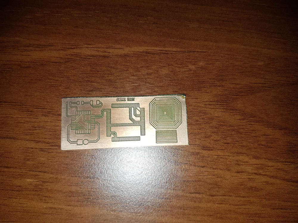
@lamikr pls see one of my very first test I made after I built my cnc. check the TQFP100 footprint.
for me, the cnc2418 was good choice. with proper assembly it is very stable and its output is stable.
I was using the cnc for designs down to 10mil traces without any issue.so, I have good experience with my low cost cnc but do to the lack of hands-on experience with other devices, I cannot compare or recommend others.
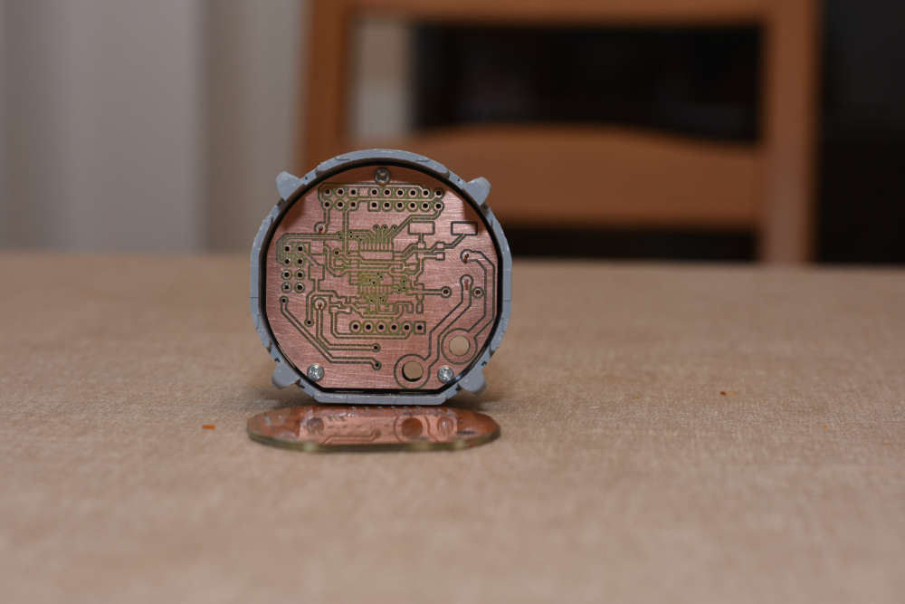
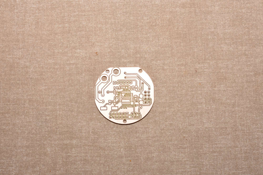
-
Hi everyone,
can someone help me pick out what to order from amazon.de?
I would like to order a 3018 pro, but which one?
What drilling bits would I need to order to mill PCB?
Any help much appreciated!!
-
@dennisc - I think its a matter of taste and preference, but there is 728 posts in this thread, many describing the pro and cons with different drillbits and mashines. Since its DIY its very hard to tell exactly what to pick - atleast for me - but lets see if someone else is bolder.
-
I know there are so many posts!
I am under a bit of time pressure and can't wait for aliexpress or bang good, so I was hoping somebody just ordered something off amazon. (and I could copy that).
I am interested in the 3018 Pro, that on looks good enough price wise at least. But maybe had an experience with Sainsmart or something else.
Other important reason is that there have not been many posts in the last months in this thread.
-
I have bought a 3018 Pro and put it together today.
I'm now trying to find out how to calibrate it, any tips would be awesome!
Im using GBRL control.
thanks!
-
Ok calibration was quite easy.
I managed to get the x, y and z axis zeroed. Only thing I am wondering is this:
I can see my file goes 0.2 mm deep. Is there a button to alter the offset?
I found I had to do all kind of fake zeroing to get it deeper!
-
@dennisc I have myself ordered the 2418 from the Jack's store.
I also ordered the parts for Ant's team's PCB machine based on the BOM on
https://bitbucket.org/compactpcbmaker/cpcbm/src/masterIt will be intersted in for comparing these two and I think money will not be wasted as other one could in the end anyway be used for drilling if other one does the route milling.
Another thing I am wondering how this will compare to Eleksmaker A3 with 405nm laser and Marco Reps modifications.
Important upgrades for the EleksMaker PCB laser CNC machine – 07:40
— Marco RepsLaser is interesting due to it's accuracy but I am worried from the reflected beams. I have only found out so classes for protecting from the beam but would rather like to see a full box made from proper shielding material on top of the Eleksmaker.
Fourths interesting thing is the openpnp based pasta dispenser and pick and place machine.
https://hackaday.io/project/165743-foxbuild-pnp
https://mcuoneclipse.com/2018/06/26/building-a-diy-smt-pickplace-machine-with-openpnp/
-
@lamikr said in CNC PCB milling:
Laser is interesting due to it's accuracy but I am worried from the reflected beams. I have only found out so classes for protecting from the beam but would rather like to see a full box made from proper shielding material on top of the Eleksmaker.
Fourths interesting thing is the openpnp based pasta dispenser and pick and place machine.
https://hackaday.io/project/165743-foxbuild-pnp
https://mcuoneclipse.com/2018/06/26/building-a-diy-smt-pickplace-machine-with-openpnp/I made an enclosure for my 3D printer in which I had a plexiglass panel for the door. Not long ago I made a mod for my 3D printer that allows me to change to different tool heads. https://www.thingiverse.com/thing:3407486
One of the tools is a 6 watt laser module. I got a piece of this to replace the plexiglass on the door of my enclosure. It is rated for the wavelength of my laser module which is 450nm. https://jtechphotonics.com/?product=445nm-laser-shielding This might be a bit small if you wanted to make a complete cover made out of this stuff though.
-
@dbemowsk Thanks for the shielding material tip, I may buy it later if starting to work with 0.5w 405nm laser for engraving. (Some safe enclosure definetly needed)
In the meantime I have not constructed my CNC 2418 from Jack's store and tested that I can control it by seding the g-gode commands from terminal. I have not yet tried to workflow from Kicad, to flatcam and from there to bCNC.
Original GRBL firmware was 0.9j but I managed to upgrade it to v1.1h over USP without need for using another arduino as a ISP programmer and wiring it to woodpecker. Arduino-ide did not detect the board automatically but the flashing to grbl 1.1h worked with a following command out of the box on my linux by using a following avrdude command:
avrdude -v -C/etc/avrdude/avrdude.conf -pm328p -carduino -P /dev/ttyUSB0 -D -Uflash:w:grbl_v1.1h.20190825.hexThis thread is so long that it takes lot of time to try to find all important steps. But what I have gathered is that 3 most important things that I am still missing before trying to mill are the
-
auto leveling
What I read, this should be easy with gBNC. Mostly connect one wire from the drilling bit to A5 pin in woodpecker and another from woodpecker's ground to pcb. -
Current adjustment for all three A4988 motors.
If I understood correctly @andrew and @NeverDie both changed that from 0.6A to 0.9A? Can that be done only by rotating the potentiometer on a4988 driver boards or do I also need to add some resistors? -
End stops modules? Could them be connected somehow to woodpecker?
-
-
Looks like the price on more precise equipment has come down:
https://www.aliexpress.com/item/32889386703.html?spm=a2g0o.detail.1000014.25.50f15e323iLiE4&gps-id=pcDetailBottomMoreOtherSeller&scm=1007.13338.141931.0&scm_id=1007.13338.141931.0&scm-url=1007.13338.141931.0&pvid=6d201006-5b15-41db-bc2e-2f9421010139Either this or a more classic mill setup is probably the most cost effective for cutting pcbs more accurately. It's the twisting slop that most limits my current CNC's PCB fidelity.
-
On my previous attempts, I wasn't aware there existed any options for milling PCB's beyond just v-bits. Now it seems that there's quite a range of actual end-mill bits in diameters as narrow as 0.05mm!
Milling PCB tracks on a Tormach with a "Very" Small End Mill – 00:53
— CNCTurboStepThey look like this:

From what I've read, when using end mills with less than 100 micron cutting diameters, it's recommended to do step cutting, due to the delicate nature of the bit. That's fine with me: once I set up the machine with a PCB blank, I can walk away and come back when it's done.
Anyone tried using end mill bits like these for milling PCB's, and if so, how do they compare?
-
@NeverDie I've got this one several months ago, I couldn't say it's a good one though.
here is the list of drawbacks I've had/have:- spindle fixed speed 12000RPM. I added automatic circuit breaker to it so it won't put home on fire when it rams into the table. (threw away DC connector on top as it wasn't reliably holding both sides to begin with and then it was burned a bit after spindle stall). Runout is about 50um. + whatever collet would add (cheapest ones from aliexpress were disappointment in a range 50~100um, so I've got precision one locally)
The only thing I'm going to invest into this machine is 24K spindle + vfd with small runout. (it just arrived but still unpacked, it will need adapter plate to mount it on Z plate, hopefully I'll make something with adjustable tilt to simplify tramming) - it was poor assembled, one has to disassemble and put it back properly tightening screws and making sure belts are not loose (that solved lost steps issue)
- it uses lead screws with bronze nuts like in 3D printers and a plastic spacer between nuts (to counter backlash).
- axis plates are attached to nuts via that same plastic spacer (not sure how it would do with milling aluminium)
- there was (still is) some backlash (~40-60um) left after tightening nuts,
one could tighten it further but that would come at cost of lower speeds as no-name steppers start stalling (currently I have 2300mm/min max on XY plane, and one would wish for more rapids if one would wish to try milling plastics) - squaring it is nightmare, basically the only option you have is adjusting X pillars and try to square XY and YZ at the same time (and there isn't much space to play with it). For tramming spindle on XZ plane, I had to move up one side of X support plate as there isn't sufficient play in spindle mount and then level sacrificial board to make X axis square to the table.
As result of several iterations, I've got ±40um difference in hight across the table. XY axises still not square ~0.5mm on opposite sides of of the table on X axis, but I don't have heart to repeat whole procedure again (yet). - controller dial is way too sensitive, so I practically don't use it at all. Ribbon cable to SD card fell appart, USB connector for PC doesn't work reliably (but mostly works if you got it in working position).
The whole setup was bought to prototype PCBs and later on learn how to mill other stuff (plastics/aluminium) for casing prototypes.
So far I've managed to mill reliably 0.3mm isolation paths with 60*0.2 engraving bit (but as you did, I've redesigned board with wider traces to reduce failure chances). In Flatcam, I had to add runout value to tip diameter to avoid track thinning. Perhaps I could do more fine traces now (after all the tuning) with more fragile 30 or 15 degree bits, but I won't try till I get current project out of the door (at least hardware part of it).
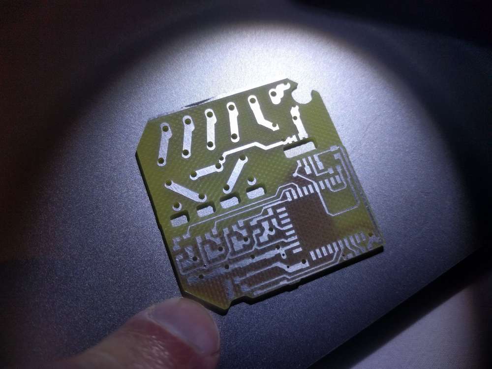
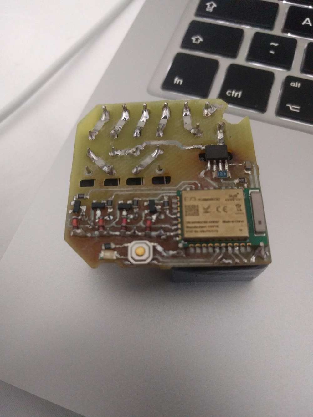
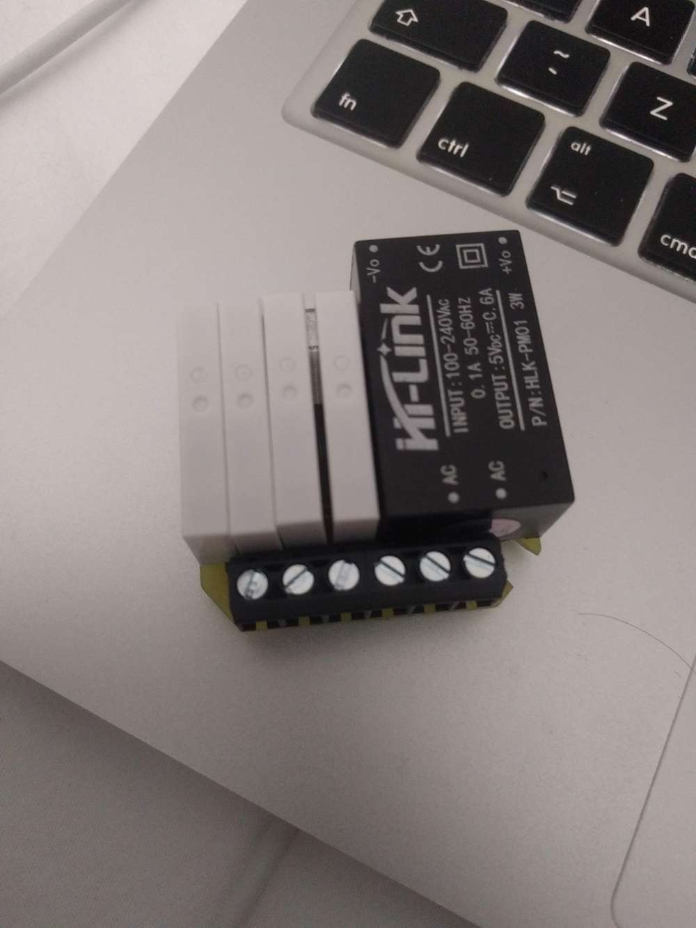
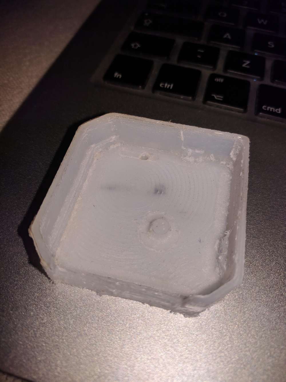
and here is my 1st attempt to mill the case part
- spindle fixed speed 12000RPM. I added automatic circuit breaker to it so it won't put home on fire when it rams into the table. (threw away DC connector on top as it wasn't reliably holding both sides to begin with and then it was burned a bit after spindle stall). Runout is about 50um. + whatever collet would add (cheapest ones from aliexpress were disappointment in a range 50~100um, so I've got precision one locally)
-
I received one of the 0.2mm end mill bits, so I'll be having a run at it with that sometime soon. To give it the best chance, I plan to bed level with some large diameter endmills first, as I haven't tried that before and maybe it will help. Looking forward to it.
Wegster has a series of impressive videos on youtube that are an inspiration that this is actually possible to do with fairly ordinary looking equipment (though they charge a small fortune for theirs):
Double layer PCB prototyping 0.1 mm traces/spaces – 12:45
— WEGSTR CNCMaybe there's more to it than meets the eye? Makes me wonder what exactly they're doing in order to accomplish it so perfectly.
An alternative might be to connect a sharpie type pen and plot that way as a prelude to chemical etching. I haven't wanted to do that, but it's a fallback that might work to get fine pitch etches.
Hackaday did a very insightful analysis of "the mother mill" which explained why it is surprisingly good at milling PCBs despite it's having a largely plastic frame construction:
https://hackaday.com/2016/08/02/the-othermill-vs-import-a-technical-comparison/
Usually success begets knock-offs, but I can't say that I've noticed any knockoffs of the OtherMill.I'd really like to have a machine with an automatic tool changer, where I could just launch it and come back when it's totally done with everything. I'm surprised that capability hasn't yet become more widespread.
-
Anyone else out there using CNC to make their own PCB's? After taking a break from it for a while, I'm going to take another stab at it, now with the benefit of fresh eyes. Right off the bat I'm making a few changes:
- Flattening a space for the PCB on the sacrificial board so that little to no bed leveling will be required:
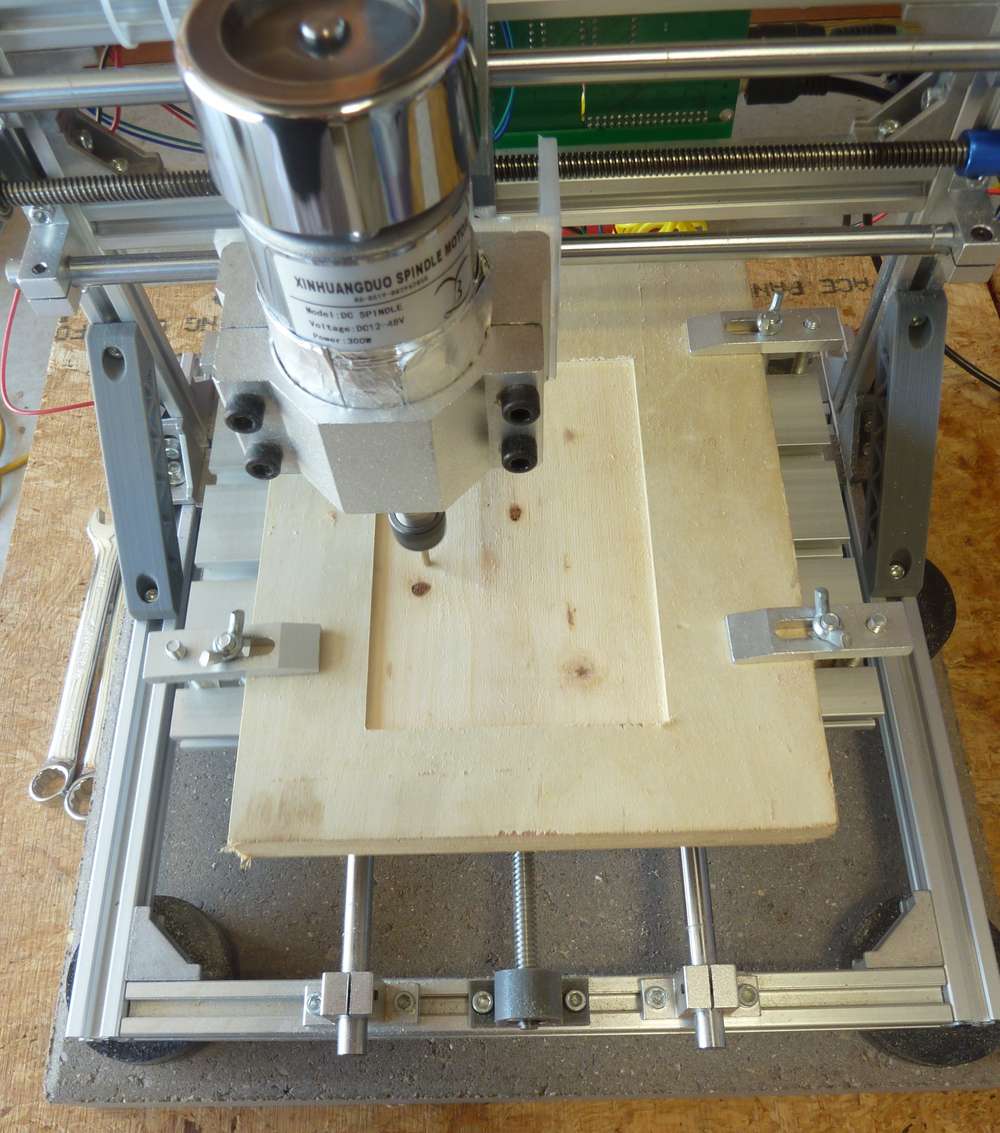
- As seen in the photo just above, using a concrete paver to stabilize the platform. This is a common tactic used in 3D printers.
- Mounting the printer on non-skid pucks (also shown in the photo) to guarantee that the CNC doesn't slide around.
- Using FR-1 instead of FR-4 as the substrate for the copper clad PCB.
- As already mentioned in the post just above, using end-mill bits instead of v-bits to accomplish the etching.
- Oh, and yes, I replaced the spindle I was previously using with this upgraded, more powerful spindle.
- Using a stronger double-sided tape ("Nitto Tape") to hold the PCB in position while the PCB is being etched by the CNC. Actually, I'm not unsure as to whether it's stronger than the double sided golf grip tape I was using previously, but I'm trying it today, so I'll soon have a basis on which to gauge it.
- Laying around somewhere I have some TMC drivers, and when I find them I'll use them to upgrade the rudimentary GRBL controller that came with the original CNC kit. Not sure if it will yield any improvements, but, meh, seems like it's worth trying.
- I've switched to a domestic fabricator of blank PCBs that I'll use instead of the Aliexpress ones. I don't know whether it will make a difference, but the quality does seem to be higher, and I can get them with thicker substrates than what I can find on aliexpress.
- I switched to a metal spindle mount.
I've already noticed one anomaly that I hadn't noticed previously, which is that if I use Flatcam to set the depth of cut to 1.5875mm (equals 1/16 of an inch), then if I do it in 4 passes (where the first pass is at 0.5mm depth, the second at 1.0mm depth, the third at 1.5mm depth, and finally the last pass at 1.5875mm, I end up getting a shallower depth of cut than if I were to later do a depth of cut of 1.5875mm in just one pass. Not sure if this is caused by an error in chillipepr, the gerbal controller, or the stepper missing steps.
Meanwhile, software seems to have improved since the last time I was using it, so I'm looking forward to trying it again as well as new alternatives. Anyone here have any favorites?
- Flattening a space for the PCB on the sacrificial board so that little to no bed leveling will be required:
-
I wasn't getting a completely smooth flattened area using just a 1/8" end mill, so I'm going to hazard a try with https://www.amazon.com/gp/product/B0000225VS/ref=ppx_yo_dt_b_asin_title_o00_s00?ie=UTF8&psc=1
by switching to a 1/4" collet in my ER11 spindle.
-
SOLVED: up until now I was running the "stable" release of FlatCAM, but it turned out to be so full of shortcomings that I decided to throw caution to the wind and install the latest beta release instead. I'm glad I did. Not only did it fix a range of problems that the stable release had, but it also has a "finishing" setting that's doing a much better job of smoothing out my spoilboard using a mere garden variety 1/8" end mill.
 The main downside is that the "finishing" algorithm can take quite a while to run, so for speed's sake I'll still give the Freund a try. Freund cutting tools are pretty good quality, so I expect it will be an improvement.
-
@niallain As far as v-bits go, I've lately had good results with this type:
https://www.amazon.com/gp/product/B019K4OMBE/ref=ppx_yo_dt_b_search_asin_title?ie=UTF8&psc=1It's not as fragile as the typical aliexpress style v-bits.
-
It's now possible to use an inexpensive open source controller to achieve both closed loop control and 0.02 degree resolution on a nema 17 stepper: https://hackaday.io/project/11224-mechaduino
I get the impression the original maker isn't selling it anymore. So, you can make it yourself from the files posted or github, or a number of inexpensive clones are also available on aliexpress for around $15. By use of a magnetic encoder, it basically immediately corrects for any missed steps. In the case of 3D printing, that means no layer shifts, even if, as demonstrated in this youtube video, you were to whack the printhead hard with a rubber mallet during a print:
S42B closed loop stepper motors - No more layer shifts! – 14:46
— Teaching TechAs for CNC, it's a new level of control assuredness.
Also, because the drivers offer a way to directly monitor how hard the servos are working, they should provide a way to make better informed decisions about increasing speed, acceleration, etc.
UStepper appears to be another board that was conceived along similar lines.
I'm planning to upgrade my nema 17's to ones with 3x the torque, and then later upgrade those upgrades with mechaduino/ustepper closed loop controllers. By sticking with nema 17, all these should be drop-in replacements for what's already there. i.e. no need to change couplers or other fittings.
For even greater torque and precision I could outfit the steppers with planetary gearboxes, but, meh, I'll evaluate that after the upgrades already pending are completed. I presume they come with a downside of much slower speed.
Anyone here done any of this? How did it go?
-
@NeverDie I recently finally made my first reliable PCBs, combining milling and laser. Both on the same Chinese build 3018. I enhanced my 3018 with a 7W laser diode a year ago. Selection of which one is the active device is done by a manual switch. Maybe some of my experiences are usefull to you or anyone else here.
For milling I nowadays completely rely on the heightmap of Candle (GRBL1.1 on a WoodPecker board, not the original board of the machine), the Gcodes generated by FlatCAM which are in turn based on the Gerbers by EasyEDA. Apart from the laser enhancement and the PCB, I feel no need to change anything on the machine anymore. I have had some serious thoughts on replacing the Z-axis part, and maybe one day I will do so.
I mill the isolation tracks in 5(!) passes. Time is no issue here; quality and reliability are. I use 30° piramyd bits, they are very well pointed and the machine has very little runout, so I realy need those five passes. I love these bits (eg https://tinyurl.com/yyg6hsft) : they're stable, sturdy, hardly breakable and when needed I can sharpen them myself.
The laser comes in when getting to the soldermask: it's cutted out in vinyl on a thin (0.1mm) sheet of silicone. Silicone does not melt, nor attach to the freshly cured ink and is reusable a couple of times.
After exposing the UVink and rinsing the unexposed ink with alcohol, I clean up the edges of the pads again with the laser on a higher power level.It was hard to get the milling bit and the laser beam zeroed at exactly the same point. But once I had: what a joy to use the techniques combined!!
-
@bikerMark said in CNC PCB milling:
Time is no issue here; quality and reliability are. I use 30° piramyd bits, they are very well pointed and the machine has very little runout, so I realy need those five passes. I love these bits (eg https://tinyurl.com/yyg6hsft) : they're stable, sturdy, hardly breakable and when needed I can sharpen them myself.
Thanks for the tip! I just now ordered some.
I'm a bit unclear as to how you are using the laser, but it sounds interesting. Although different from what you are doing, I imagine that using a uv laser to selectively cure solder mask would be the ultimate. By not curing the solder mask over the pads, you could just wash the uncured soldermask off later. Would it work? I guess it depends on whether the uv laser can be focused well enough that it only exposes what you want it to.
How fine a pitch can you etch with your setup? That's the real test, especially given how finely pitched a lot of smd parts are.
-
@bikerMark At the beginning of this youtube the guy utilizes a laser to do very selective curing of a PCB's etching mask:
How to make a Giant Mosfet | Best DIY project for 2020 – 17:09
— American TechFirst time I've seen it actually done. I presume the very same approach might work for solder mask too?
-
I just now came across a dedicated autoleveling program that allows you to do a two-stage autoleveling. This has at least a couple of advantages over the much more common one-stage autolevelers that's typically encountered: 1. you only need to probe once. If your CNC job gets derailed, you don't have to re-probe, and 2. you have the opportunity to review and correct the probing values in case something went amiss during the probing. AFAIK, this program should be compatible with whatever g-code sender you may wish to use.
2-stage levelling with AutolevellerAE v0.7.6 – 04:31
— daedelus1982For instance, auto-leveling has been broken in the Universal G-Code Sender for over a year now. Perhaps this could fill the autolevelling need not currently being met by UGS.
[One thing I like about UGS is that it constantly updates its best guess as to the estimated time of job completion. Very handy! Seems like an obvious feature for a g-code sender to have, and yet many/most g-code senders that I've tried seem to lack it.]
-
For flattening the spoilboard, I ended up trying the 1/2" freund:
https://www.amazon.com/gp/product/B00004T7BL/ref=ppx_yo_dt_b_asin_title_o04_s00?ie=UTF8&psc=1
rather than the 1/4" freuend. No worries: it posed no challenge for my spindle motor.The problem is that, unlike a fly cutter, this straight bit effectively cuts a kind of donut
around the central shaft, beause the blades do not extend inward enough. Even though moving the bit far enough will effectively erase the donut, I'm concerned it may create unnecessary resistance to downward plunging if the spindle is holding stationary in the XY plane. Therefore, the next bit I'm going to try is:
https://www.amazon.com/Cleaning-Diameter-Spoilboard-Surfacing-Proburs/dp/B07BF5ZHD1/ref=cm_cr_arp_d_product_top?ie=UTF8
which looks to be more like a fly cutter and, if so, should avoid creating pegs directly underneath the spinning shaft.I'm also going to try:
https://smile.amazon.com/Spoilboard-Surfacing-Diameter-Flattening-NITOMAK/dp/B07ZP5RXRP/ref=sr_1_1?dchild=1&keywords=CNC+Spoilboard+Surfacing+Router+Bits%2C+1%2F4+inch+Shank+1+inch+Cutting+Diameter%2C+Slab+Flattening+Router+Bit+Planing+Bit+Wood+Planing+Bit+Dado+Planer+Bit+by+NITOMAK+(Carbide)&qid=1596707793&s=industrial&sr=1-1
simply because it is so highly rated for flattening a spoilboard, even though it is likely to produce some amount of pegging directly beneath a shaft that is not moving in the XY plane.