@rejoe2
Hi,
Thanks for feedback, I'll try code from alowhum first.
1kohm
@1kohm
Posts
-
Help to optimize my sketch -
Help to optimize my sketch -
Help to optimize my sketch@alowhum
yes, tried to use loops but no luck so far.I have one loop with viarable
#define NUMBER_OF_RELAYS 8 // Total number of attached relayswhich then is used
void before() {
  for (int sensor=1, pin=RELAY_0; sensor<=NUMBER_OF_RELAYS;sensor++, pin++) {
    // Then set relay pins in output mode
    pinMode(pin, OUTPUT);
    // Set relay to last known state (using eeprom storage)
    digitalWrite(pin, loadState(sensor)?RELAY_ON:RELAY_OFF);
  }
}
but how to use it i.e. for
Bounce debouncerMaybe you can explain.
Thanks -
Help to optimize my sketch@mfalkvidd said in Help to optimize my sketch:
maintainability
Hi,
yes, I'd like to optimize readability/maintainability of that code. RAM or flash size does not mater currently.
I want to learn more how to use loops and #define parameters for more transparency. -
Help to optimize my sketchHi,
I've wrote some bad code and I'm sure that someone here can help me to optimize it. I'm still begginer.
Goal:
- Serial gateway for Domoticz system without any wireless nodes
- running on Arduino Mega 2560
- 8 relays with digital input buttons
- 8 digital input for door contact (currently 3 implemented)
- temperature sensord on 1 wire in future
// Enable debug prints to serial monitor #define MY_DEBUG // Enable and select radio type attached //#define MY_RADIO_NRF24 //#define MY_RADIO_RFM69 // Set LOW transmit power level as default, if you have an amplified NRF-module and // power your radio separately with a good regulator you can turn up PA level. //#define MY_RF24_PA_LEVEL RF24_PA_LOW // Enable serial gateway #define MY_GATEWAY_SERIAL // Define a lower baud rate for Arduino's running on 8 MHz (Arduino Pro Mini 3.3V & SenseBender) #if F_CPU == 8000000L #define MY_BAUD_RATE 38400 #endif // Flash leds on rx/tx/err //#define MY_LEDS_BLINKING_FEATURE // Set blinking period #define MY_DEFAULT_LED_BLINK_PERIOD 300 // Inverses the behavior of leds // #define MY_WITH_LEDS_BLINKING_INVERSE // Enable inclusion mode #define MY_INCLUSION_MODE_FEATURE // Enable Inclusion mode button on gateway #define MY_INCLUSION_BUTTON_FEATURE // Inverses behavior of inclusion button (if using external pullup) //#define MY_INCLUSION_BUTTON_EXTERNAL_PULLUP // Set inclusion mode duration (in seconds) #define MY_INCLUSION_MODE_DURATION 120 // Digital pin used for inclusion mode button #define MY_INCLUSION_MODE_BUTTON_PIN 3 // Flash leds on rx/tx/err #define MY_DEFAULT_ERR_LED_PIN 22 // Error led pin #define MY_DEFAULT_RX_LED_PIN 24 // Receive led pin #define MY_DEFAULT_TX_LED_PIN 26 // the PCB, on board LED #include <SPI.h> #include <MySensors.h> #include <Bounce2.h> // Enable repeater functionality for this node #define MY_REPEATER_FEATURE //=RELAY= #define RELAY_0 4 // Arduino Digital I/O pin number for first relay (second on pin+1 etc) #define RELAY_1 5 #define RELAY_2 6 #define RELAY_3 7 #define RELAY_4 8 #define RELAY_5 9 #define RELAY_6 10 #define RELAY_7 11 #define NUMBER_OF_RELAYS 8 // Total number of attached relays #define RELAY_ON 0 // GPIO value to write to turn on attached relay #define RELAY_OFF 1 // GPIO value to write to turn off attached relay #define BUTTON0_PIN A0 #define BUTTON1_PIN A1 #define BUTTON2_PIN A2 #define BUTTON3_PIN A3 #define BUTTON4_PIN A4 #define BUTTON5_PIN A5 #define BUTTON6_PIN A6 #define BUTTON7_PIN A7 //=RELAY= //=DIGITAL_INPUT= #define CHILD_ID_DIGITAL8 10 #define CHILD_ID_DIGITAL9 11 #define CHILD_ID_DIGITAL10 12 #define BUTTON8_PIN A8 // Arduino Digital I/O pin for button/reed switch #define BUTTON9_PIN A9 // Arduino Digital I/O pin for button/reed switch #define BUTTON10_PIN A10 // Arduino Digital I/O pin for button/reed switch int oldValue8=-1; int oldValue9=-1; int oldValue10=-1; // Initialize message MyMessage msg8(CHILD_ID_DIGITAL8, V_TRIPPED); MyMessage msg9(CHILD_ID_DIGITAL9, V_TRIPPED); MyMessage msg10(CHILD_ID_DIGITAL10, V_TRIPPED); //=DIGITAL_INPUT= void before() { for (int sensor=1, pin=RELAY_0; sensor<=NUMBER_OF_RELAYS;sensor++, pin++) { // Then set relay pins in output mode pinMode(pin, OUTPUT); // Set relay to last known state (using eeprom storage) digitalWrite(pin, loadState(sensor)?RELAY_ON:RELAY_OFF); } } Bounce debouncer0 = Bounce(); Bounce debouncer1 = Bounce(); Bounce debouncer2 = Bounce(); Bounce debouncer3 = Bounce(); Bounce debouncer4 = Bounce(); Bounce debouncer5 = Bounce(); Bounce debouncer6 = Bounce(); Bounce debouncer7 = Bounce(); Bounce debouncer8 = Bounce(); Bounce debouncer9 = Bounce(); Bounce debouncer10 = Bounce(); void setup() { // Setup locally attached sensors delay(5000); // Setup the button. pinMode(BUTTON0_PIN, INPUT_PULLUP); pinMode(BUTTON1_PIN, INPUT_PULLUP); pinMode(BUTTON2_PIN, INPUT_PULLUP); pinMode(BUTTON3_PIN, INPUT_PULLUP); pinMode(BUTTON4_PIN, INPUT_PULLUP); pinMode(BUTTON5_PIN, INPUT_PULLUP); pinMode(BUTTON6_PIN, INPUT_PULLUP); pinMode(BUTTON7_PIN, INPUT_PULLUP); pinMode(BUTTON8_PIN, INPUT_PULLUP); pinMode(BUTTON9_PIN, INPUT_PULLUP); pinMode(BUTTON10_PIN, INPUT_PULLUP); // After setting up the button, setup debouncer. debouncer0.attach(BUTTON0_PIN); debouncer0.interval(5); debouncer1.attach(BUTTON1_PIN); debouncer1.interval(5); debouncer2.attach(BUTTON2_PIN); debouncer2.interval(5); debouncer3.attach(BUTTON3_PIN); debouncer3.interval(5); debouncer4.attach(BUTTON4_PIN); debouncer4.interval(5); debouncer5.attach(BUTTON5_PIN); debouncer5.interval(5); debouncer6.attach(BUTTON6_PIN); debouncer6.interval(5); debouncer7.attach(BUTTON7_PIN); debouncer7.interval(5); debouncer8.attach(BUTTON8_PIN); debouncer8.interval(5); debouncer9.attach(BUTTON9_PIN); debouncer9.interval(5); debouncer10.attach(BUTTON10_PIN); debouncer10.interval(5); //presentation(); } void presentation() { // Send the sketch version information to the gateway and Controller sendSketchInfo("Arduino SmartHub 1", "1.0"); present(CHILD_ID_DIGITAL8, S_DOOR); present(CHILD_ID_DIGITAL9, S_DOOR); present(CHILD_ID_DIGITAL10, S_DOOR); for (int sensor=1, pin=RELAY_0; sensor<=NUMBER_OF_RELAYS;sensor++, pin++) { // Register all sensors to gw (they will be created as child devices) present(sensor, S_LIGHT); } } // Initialize Relay message MyMessage msg0(0, V_LIGHT); MyMessage msg1(1, V_LIGHT); MyMessage msg2(2, V_LIGHT); MyMessage msg3(3, V_LIGHT); MyMessage msg4(4, V_LIGHT); MyMessage msg5(5, V_LIGHT); MyMessage msg6(6, V_LIGHT); MyMessage msg7(7, V_LIGHT); void loop() { // Send locally attached sensor data here if (debouncer0.update()) { // Get the update value. int value0 = debouncer0.read(); // Send in the new value. if(value0 == LOW){ saveState(1, !loadState(1)); digitalWrite(RELAY_0, loadState(1)?RELAY_ON:RELAY_OFF); send(msg0.set(loadState(1))); } } if (debouncer1.update()) { int value1 = debouncer1.read(); if(value1 == LOW){ saveState(2, !loadState(2)); digitalWrite(RELAY_1, loadState(2)?RELAY_ON:RELAY_OFF); send(msg1.set(loadState(2))); } } if (debouncer2.update()) { int value2 = debouncer2.read(); if(value2 == LOW){ saveState(3, !loadState(3)); digitalWrite(RELAY_2, loadState(3)?RELAY_ON:RELAY_OFF); send(msg2.set(loadState(3))); } } if (debouncer3.update()) { int value3 = debouncer3.read(); if(value3 == LOW){ saveState(4, !loadState(4)); digitalWrite(RELAY_3, loadState(4)?RELAY_ON:RELAY_OFF); send(msg3.set(loadState(4))); } } if (debouncer4.update()) { int value4 = debouncer4.read(); if(value4 == LOW){ saveState(5, !loadState(5)); digitalWrite(RELAY_4, loadState(5)?RELAY_ON:RELAY_OFF); send(msg4.set(loadState(5))); } } if (debouncer5.update()) { int value5 = debouncer5.read(); if(value5 == LOW){ saveState(6, !loadState(6)); digitalWrite(RELAY_5, loadState(6)?RELAY_ON:RELAY_OFF); send(msg5.set(loadState(6))); } } if (debouncer6.update()) { int value6 = debouncer6.read(); if(value6 == LOW){ saveState(7, !loadState(7)); digitalWrite(RELAY_6, loadState(7)?RELAY_ON:RELAY_OFF); send(msg6.set(loadState(7))); } } if (debouncer7.update()) { int value7 = debouncer7.read(); if(value7 == LOW){ saveState(8, !loadState(8)); digitalWrite(RELAY_7, loadState(8)?RELAY_ON:RELAY_OFF); send(msg7.set(loadState(8))); } } if (debouncer8.update()) { // Get the update value. int value8 = debouncer8.read(); // Send in the new value. if (value8 != oldValue8) { // Send in the new value send(msg8.set(value8==HIGH ? 1 : 0)); oldValue8 = value8; } } if (debouncer9.update()) { // Get the update value. int value9 = debouncer9.read(); // Send in the new value. if (value9 != oldValue9) { // Send in the new value send(msg9.set(value9==HIGH ? 1 : 0)); oldValue9 = value9; } } if (debouncer10.update()) { // Get the update value. int value10 = debouncer10.read(); // Send in the new value. if (value10 != oldValue10) { // Send in the new value send(msg10.set(value10==HIGH ? 1 : 0)); oldValue10 = value10; } } } void receive(const MyMessage &message) { // We only expect one type of message from controller. But we better check anyway. if (message.type==V_LIGHT) { // Change relay state digitalWrite(message.sensor-1+RELAY_1, message.getBool()?RELAY_ON:RELAY_OFF); // Store state in eeprom saveState(message.sensor, message.getBool()); // Write some debug info Serial.print("Incoming change for sensor:"); Serial.print(message.sensor); Serial.print(", New status: "); Serial.println(message.getBool()); } } -
Gas MeterHi,
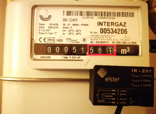
I'm working on gas meter using In-Z61 reed sensor - it's dedicated for gas meters.
My node is build based on https://www.mysensors.org/hardware/ac-dc-ssd-relay
My controller is Domo: v3.8258
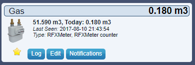
My gateway is Arduino UNO shieldData is send over to Domo as designed
One full rotare of gas meter 00.000 [m3] -> 00.010 [m3] is one impuls triggered by reed sensor.This is working - after one rotare i got value send to Domo:
The issue is that after some while the counter still increments - no actual meter movement is done
Below is debug - pulse was 100 and was changed to 101.pulsecount:100 TSP:MSG:SEND 8-8-0-0 s=1,c=1,t=24,pt=5,l=4,sg=0,ft=0,st=ok:100 volume:0.100 TSP:MSG:SEND 8-8-0-0 s=1,c=1,t=35,pt=7,l=5,sg=0,ft=0,st=ok:0.100 TSP:MSG:READ 7-7-255 s=255,c=3,t=7,pt=0,l=0,sg=0: TSP:MSG:BC TSP:MSG:READ 7-7-255 s=255,c=3,t=7,pt=0,l=0,sg=0: TSP:MSG:BC l/min:0.03 TSP:MSG:SEND 8-8-0-0 s=1,c=1,t=34,pt=7,l=5,sg=0,ft=0,st=ok:0.03 pulsecount:101 TSP:MSG:SEND 8-8-0-0 s=1,c=1,t=24,pt=5,l=4,sg=0,ft=0,st=ok:101 volume:0.101 TSP:MSG:SEND 8-8-0-0 s=1,c=1,t=35,pt=7,l=5,sg=0,ft=0,st=ok:0.101 TSP:MSG:READ 7-7-255 s=255,c=3,t=7,pt=0,l=0,sg=0: TSP:MSG:BC pulsecount:101As a sketch I use modified version of PulseWaterMeter - https://www.mysensors.org/build/pulse_water
I changed presentation:
present(CHILD_ID, S_GAS);and added node temp sensor:
present(CHILD_DSB_ID, S_TEMP);It looks like some kind of bouncing effect, but have no idea why counter increments itself.
Help me out to make the code more clear and free of errors.
code below:
/** * The MySensors Arduino library handles the wireless radio link and protocol * between your home built sensors/actuators and HA controller of choice. * The sensors forms a self healing radio network with optional repeaters. Each * repeater and gateway builds a routing tables in EEPROM which keeps track of the * network topology allowing messages to be routed to nodes. * * Created by Henrik Ekblad <henrik.ekblad@mysensors.org> * Copyright (C) 2013-2015 Sensnology AB * Full contributor list: https://github.com/mysensors/Arduino/graphs/contributors * * Documentation: http://www.mysensors.org * Support Forum: http://forum.mysensors.org * * This program is free software; you can redistribute it and/or * modify it under the terms of the GNU General Public License * version 2 as published by the Free Software Foundation. * ******************************* * * REVISION HISTORY * Version 1.0 - Henrik Ekblad * Version 1.1 - GizMoCuz * * DESCRIPTION * Use this sensor to measure volume and flow of your house watermeter. * You need to set the correct pulsefactor of your meter (pulses per m3). * The sensor starts by fetching current volume reading from gateway (VAR 1). * Reports both volume and flow back to gateway. * * Unfortunately millis() won't increment when the Arduino is in * sleepmode. So we cannot make this sensor sleep if we also want * to calculate/report flow. * http://www.mysensors.org/build/pulse_water */ // Enable debug prints to serial monitor #define MY_DEBUG // Enable and select radio type attached #define MY_RADIO_NRF24 //#define MY_RADIO_NRF5_ESB //#define MY_RADIO_RFM69 //#define MY_RADIO_RFM95 #include <MySensors.h> #include <SPI.h> #include <Bounce2.h> #include <OneWire.h> #include <DallasTemperature.h> #define CHILD_DSB_ID 13 #define ONE_WIRE_BUS 8 #define DIGITAL_INPUT_SENSOR 3 // The digital input you attached your sensor. (Only 2 and 3 generates interrupt!) #define PULSE_FACTOR 1000 // Nummber of blinks per m3 of your meter (One rotation/liter) #define SLEEP_MODE false // flowvalue can only be reported when sleep mode is false. #define MAX_FLOW 40 // Max flow (l/min) value to report. This filters outliers. #define CHILD_ID 1 // Id of the sensor child unsigned long SEND_FREQUENCY = 3000; // Minimum time between send (in milliseconds). We don't want to spam the gateway. Bounce debouncer = Bounce(); int oldValue = 0; bool state; Bounce debouncer2 = Bounce(); int oldValue2 = 0; bool state2; MyMessage flowMsg(CHILD_ID,V_FLOW); MyMessage volumeMsg(CHILD_ID,V_VOLUME); MyMessage lastCounterMsg(CHILD_ID,V_VAR1); MyMessage msgTemp(CHILD_DSB_ID, V_TEMP); OneWire oneWire(ONE_WIRE_BUS); DallasTemperature sensors(&oneWire); // Pass the oneWire reference to Dallas Temperature. double ppl = ((double)PULSE_FACTOR)/1000; // Pulses per liter volatile unsigned long pulseCount = 0; volatile unsigned long lastBlink = 0; volatile double flow = 0; bool pcReceived = false; unsigned long oldPulseCount = 0; unsigned long newBlink = 0; double oldflow = 0; double volume =0; double oldvolume =0; unsigned long lastSend =0; unsigned long lastPulse =0; void setup() { // initialize our digital pins internal pullup resistor so one pulse switches from high to low (less distortion) pinMode(DIGITAL_INPUT_SENSOR, INPUT_PULLUP); pulseCount = oldPulseCount = 0; // Fetch last known pulse count value from gw request(CHILD_ID, V_VAR1); lastSend = lastPulse = millis(); attachInterrupt(digitalPinToInterrupt(DIGITAL_INPUT_SENSOR), onPulse, FALLING); } void presentation() { // Send the sketch version information to the gateway and Controller sendSketchInfo("Gas Meter", "1.1"); // Register this device as Waterflow sensor present(CHILD_ID, S_GAS); present(CHILD_DSB_ID, S_TEMP); } void loop() { static float prevTemp = 0; unsigned long currentTime = millis(); // Only send values at a maximum frequency or woken up from sleep if (SLEEP_MODE || (currentTime - lastSend > SEND_FREQUENCY)) { lastSend=currentTime; if (!pcReceived) { //Last Pulsecount not yet received from controller, request it again request(CHILD_ID, V_VAR1); return; } if (!SLEEP_MODE && flow != oldflow) { oldflow = flow; Serial.print("l/min:"); Serial.println(flow); // Check that we dont get unresonable large flow value. // could hapen when long wraps or false interrupt triggered if (flow<((unsigned long)MAX_FLOW)) { send(flowMsg.set(flow, 2)); // Send flow value to gw } } // No Pulse count received in 2min if(currentTime - lastPulse > 120000) { flow = 0; } // Pulse count has changed if ((pulseCount != oldPulseCount)||(!SLEEP_MODE)) { oldPulseCount = pulseCount; Serial.print("pulsecount:"); Serial.println(pulseCount); send(lastCounterMsg.set(pulseCount)); // Send pulsecount value to gw in VAR1 double volume = ((double)pulseCount/((double)PULSE_FACTOR)); if ((volume != oldvolume)||(!SLEEP_MODE)) { oldvolume = volume; Serial.print("volume:"); Serial.println(volume, 3); send(volumeMsg.set(volume, 3)); // Send volume value to gw } } // Fetch temperatures from Dallas sensors sensors.requestTemperatures(); // Fetch and round temperature to one decimal float temperature = static_cast<float>(static_cast<int>(sensors.getTempCByIndex(0) * 10.f)) / 10.f; if (temperature != -127.00f && temperature != 85.00f && prevTemp != temperature) { // Send in the new temperature send(msgTemp.set(temperature, 1)); Serial.print("Sent temperature: "); Serial.println(temperature); prevTemp = temperature; } } if (SLEEP_MODE) { sleep(SEND_FREQUENCY); } } void receive(const MyMessage &message) { if (message.type==V_VAR1) { unsigned long gwPulseCount=message.getULong(); pulseCount += gwPulseCount; flow=oldflow=0; Serial.print("Received last pulse count from gw:"); Serial.println(pulseCount); pcReceived = true; } } void onPulse() { if (!SLEEP_MODE) { unsigned long newBlink = micros(); unsigned long interval = newBlink-lastBlink; if (interval!=0) { lastPulse = millis(); if (interval<500000L) { // Sometimes we get interrupt on RISING, 500000 = 0.5sek debounce ( max 120 l/min) return; } flow = (60000000.0 /interval) / ppl; } lastBlink = newBlink; } pulseCount++; } -
Gateway update? -
Gateway update?Want to present the device as S_GAS
void presentation()
{
    // Send the sketch version information to the gateway and Controller
    sendSketchInfo("Gas Meter", "1.1");

    // Register this device as Waterflow sensor
    present(CHILD_ID, S_GAS);
}
Sketch I use:
/** * The MySensors Arduino library handles the wireless radio link and protocol * between your home built sensors/actuators and HA controller of choice. * The sensors forms a self healing radio network with optional repeaters. Each * repeater and gateway builds a routing tables in EEPROM which keeps track of the * network topology allowing messages to be routed to nodes. * * Created by Henrik Ekblad <henrik.ekblad@mysensors.org> * Copyright (C) 2013-2015 Sensnology AB * Full contributor list: https://github.com/mysensors/Arduino/graphs/contributors * * Documentation: http://www.mysensors.org * Support Forum: http://forum.mysensors.org * * This program is free software; you can redistribute it and/or * modify it under the terms of the GNU General Public License * version 2 as published by the Free Software Foundation. * ******************************* * * REVISION HISTORY * Version 1.0 - Henrik Ekblad * Version 1.1 - GizMoCuz * * DESCRIPTION * Use this sensor to measure volume and flow of your house watermeter. * You need to set the correct pulsefactor of your meter (pulses per m3). * The sensor starts by fetching current volume reading from gateway (VAR 1). * Reports both volume and flow back to gateway. * * Unfortunately millis() won't increment when the Arduino is in * sleepmode. So we cannot make this sensor sleep if we also want * to calculate/report flow. * http://www.mysensors.org/build/pulse_water */ // Enable debug prints to serial monitor #define MY_DEBUG // Enable and select radio type attached #define MY_RADIO_NRF24 //#define MY_RADIO_NRF5_ESB //#define MY_RADIO_RFM69 //#define MY_RADIO_RFM95 #include <MySensors.h> #define DIGITAL_INPUT_SENSOR 7 // The digital input you attached your sensor. (Only 2 and 3 generates interrupt!) #define PULSE_FACTOR 1000 // Nummber of blinks per m3 of your meter (One rotation/liter) #define SLEEP_MODE false // flowvalue can only be reported when sleep mode is false. #define MAX_FLOW 40 // Max flow (l/min) value to report. This filters outliers. #define CHILD_ID 1 // Id of the sensor child unsigned long SEND_FREQUENCY = 3000; // Minimum time between send (in milliseconds). We don't want to spam the gateway. MyMessage flowMsg(CHILD_ID,V_FLOW); MyMessage volumeMsg(CHILD_ID,V_VOLUME); MyMessage lastCounterMsg(CHILD_ID,V_VAR1); double ppl = ((double)PULSE_FACTOR)/1000; // Pulses per liter volatile unsigned long pulseCount = 0; volatile unsigned long lastBlink = 0; volatile double flow = 0; bool pcReceived = false; unsigned long oldPulseCount = 0; unsigned long newBlink = 0; double oldflow = 0; double volume =0; double oldvolume =0; unsigned long lastSend =0; unsigned long lastPulse =0; void setup() { // initialize our digital pins internal pullup resistor so one pulse switches from high to low (less distortion) pinMode(DIGITAL_INPUT_SENSOR, INPUT_PULLUP); pulseCount = oldPulseCount = 0; // Fetch last known pulse count value from gw request(CHILD_ID, V_VAR1); lastSend = lastPulse = millis(); attachInterrupt(digitalPinToInterrupt(DIGITAL_INPUT_SENSOR), onPulse, FALLING); } void presentation() { // Send the sketch version information to the gateway and Controller sendSketchInfo("Gas Meter", "1.1"); // Register this device as Waterflow sensor present(CHILD_ID, S_GAS); } void loop() { unsigned long currentTime = millis(); // Only send values at a maximum frequency or woken up from sleep if (SLEEP_MODE || (currentTime - lastSend > SEND_FREQUENCY)) { lastSend=currentTime; if (!pcReceived) { //Last Pulsecount not yet received from controller, request it again request(CHILD_ID, V_VAR1); return; } if (!SLEEP_MODE && flow != oldflow) { oldflow = flow; Serial.print("l/min:"); Serial.println(flow); // Check that we dont get unresonable large flow value. // could hapen when long wraps or false interrupt triggered if (flow<((unsigned long)MAX_FLOW)) { send(flowMsg.set(flow, 2)); // Send flow value to gw } } // No Pulse count received in 2min if(currentTime - lastPulse > 120000) { flow = 0; } // Pulse count has changed if ((pulseCount != oldPulseCount)||(!SLEEP_MODE)) { oldPulseCount = pulseCount; Serial.print("pulsecount:"); Serial.println(pulseCount); send(lastCounterMsg.set(pulseCount)); // Send pulsecount value to gw in VAR1 double volume = ((double)pulseCount/((double)PULSE_FACTOR)); if ((volume != oldvolume)||(!SLEEP_MODE)) { oldvolume = volume; Serial.print("volume:"); Serial.println(volume, 3); send(volumeMsg.set(volume, 3)); // Send volume value to gw } } } if (SLEEP_MODE) { sleep(SEND_FREQUENCY); } } void receive(const MyMessage &message) { if (message.type==V_VAR1) { unsigned long gwPulseCount=message.getULong(); pulseCount += gwPulseCount; flow=oldflow=0; Serial.print("Received last pulse count from gw:"); Serial.println(pulseCount); pcReceived = true; } } void onPulse() { if (!SLEEP_MODE) { unsigned long newBlink = micros(); unsigned long interval = newBlink-lastBlink; if (interval!=0) { lastPulse = millis(); if (interval<500000L) { // Sometimes we get interrupt on RISING, 500000 = 0.5sek debounce ( max 120 l/min) return; } flow = (60000000.0 /interval) / ppl; } lastBlink = newBlink; } pulseCount++; } -
Gateway update?Hi,
so my node is sending data every 3 seconds
TSP:MSG:SEND 7-7-0-0 s=1,c=1,t=24,pt=5,l=4,sg=0,ft=0,st=ok:2
volume:0.002
TSP:MSG:SEND 7-7-0-0 s=1,c=1,t=35,pt=7,l=5,sg=0,ft=0,st=ok:0.002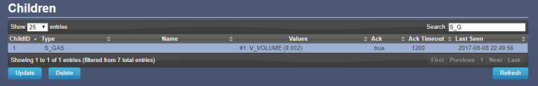
Domoticz see the updated vaule, but not in Devices :(
-
Gateway update?Hi,
radio was the issue (placed oposite.., by bad)
Now, I've uploaded node ver.2.0.0.
Starting sensor (RNNNA-, 2.0.0)
TSM:INIT
TSM:RADIO:OK
TSP:ASSIGNID:OK (ID=4)
TSM:FPAR
TSP:MSG:SEND 4-4-255-255 s=255,c=3,t=7,pt=0,l=0,sg=0,ft=0,st=bc:
TSP:MSG:READ 0-0-4 s=255,c=3,t=8,pt=1,l=1,sg=0:0
TSP:MSG:FPAR RES (ID=0, dist=0)
TSP:MSG:PAR OK (ID=0, dist=1)
TSM:FPAR:OK
TSM:ID
TSM:CHKID:OK (ID=4)
TSM:UPL
TSP:PING:SEND (dest=0)
TSP:MSG:SEND 4-4-0-0 s=255,c=3,t=24,pt=1,l=1,sg=0,ft=0,st=ok:1
TSP:MSG:READ 0-0-4 s=255,c=3,t=25,pt=1,l=1,sg=0:1
TSP:MSG:PONG RECV (hops=1)
TSP:CHKUPL:OK
TSM:UPL:OK
TSM:READY
TSP:MSG:SEND 4-4-0-0 s=255,c=3,t=15,pt=6,l=2,sg=0,ft=0,st=ok:0100
TSP:MSG:SEND 4-4-0-0 s=255,c=0,t=17,pt=0,l=5,sg=0,ft=0,st=ok:2.0.0
TSP:MSG:SEND 4-4-0-0 s=255,c=3,t=6,pt=1,l=1,sg=0,ft=0,st=ok:0
TSP:MSG:READ 0-0-4 s=255,c=3,t=15,pt=6,l=2,sg=0:0100
TSP:MSG:READ 0-0-4 s=255,c=3,t=6,pt=0,l=1,sg=0:M
TSP:MSG:SEND 4-4-0-0 s=255,c=3,t=11,pt=0,l=25,sg=0,ft=0,st=ok:Double Relay & Button tes
TSP:MSG:SEND 4-4-0-0 s=255,c=3,t=12,pt=0,l=3,sg=0,ft=0,st=ok:0.3
TSP:MSG:SEND 4-4-0-0 s=8,c=0,t=3,pt=0,l=0,sg=0,ft=0,st=ok:
TSP:MSG:SEND 4-4-0-0 s=9,c=0,t=3,pt=0,l=0,sg=0,ft=0,st=ok:
Request registration...
TSP:MSG:SEND 4-4-0-0 s=255,c=3,t=26,pt=1,l=1,sg=0,ft=0,st=ok:2
TSP:MSG:READ 0-0-4 s=255,c=3,t=27,pt=1,l=1,sg=0:1
Node registration=1
Init complete, id=4, parent=0, distance=1, registration=1
Debug looks perfect..., but cannot see the node in Domoticz i Devices tab :(
I can see the node under Hardware -> MySensorsGateway only:
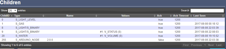
I want to test gas meter IN-Z61.
-
Gateway update?Hi,
Here's my debug from Ethernet (Arduino Uno + shield) gateway:
0;255;3;0;9;Starting gateway (RNNGA-, 2.0.0)
0;255;3;0;9;TSM:INIT
0;255;3;0;9;TSM:RADIO:OK
0;255;3;0;9;TSM:GW MODE
0;255;3;0;9;TSM:READY
IP: 10.0.0.104
0;255;3;0;9;No registration required
0;255;3;0;9;Init complete, id=0, parent=0, distance=0, registration=1
0;255;3;0;9;TSP:MSG:READ 21-21-0 s=1,c=1,t=0,pt=7,l=5,sg=0:26.0
0;255;3;0;9;TSP:MSG:READ 21-21-0 s=1,c=1,t=0,pt=7,l=5,sg=0:25.9
0;255;3;0;9;TSP:MSG:READ 8-8-0 s=0,c=1,t=37,pt=7,l=5,sg=0:50.87
0;255;3;0;9;TSP:MSG:READ 8-8-0 s=2,c=1,t=0,pt=7,l=5,sg=0:22.0
0;255;3;0;9;TSP:MSG:READ 8-8-0 s=0,c=1,t=37,pt=7,l=5,sg=0:61.50
0;255;3;0;9;TSP:MSG:READ 8-8-0 s=2,c=1,t=0,pt=7,l=5,sg=0:21.9
0;255;3;0;9;TSP:MSG:READ 8-8-0 s=1,c=1,t=1,pt=7,l=5,sg=0:40.7
0;255;3;0;9;TSP:MSG:READ 8-8-0 s=0,c=1,t=37,pt=7,l=5,sg=0:51.34
0;255;3;0;9;TSP:MSG:READ 21-21-0 s=1,c=1,t=0,pt=7,l=5,sg=0:26.0
0;255;3;0;9;TSP:MSG:READ 3-3-0 s=13,c=1,t=0,pt=7,l=5,sg=0:27.7
0;255;3;0;9;TSP:MSG:READ 21-21-0 s=1,c=1,t=0,pt=7,l=5,sg=0:25.9
0;255;3;0;9;TSP:MSG:READ 8-8-0 s=0,c=1,t=37,pt=7,l=5,sg=0:37.04
0;255;3;0;9;TSP:MSG:READ 21-21-0 s=1,c=1,t=0,pt=7,l=5,sg=0:26.0
0;255;3;0;9;TSP:MSG:READ 21-21-0 s=1,c=1,t=0,pt=7,l=5,sg=0:25.9
0;255;3;0;9;TSP:MSG:READ 21-21-0 s=1,c=1,t=0,pt=7,l=5,sg=0:26.0
0;255;3;0;9;TSP:MSG:READ 8-8-0 s=2,c=1,t=0,pt=7,l=5,sg=0:22.0
My nodes are sending data.
Want to add new node and here's the problem:
0 MCO:BGN:INIT NODE,CP=RNNNA--,VER=2.1.0
3 TSM:INIT
6 TSF:WUR:MS=0
13 !TSM:INIT:TSP FAIL
15 TSM:FAIL:CNT=1
16 TSM:FAIL:PDT
10019 TSM:FAIL:RE-INIT
10021 TSM:INIT
10028 !TSM:INIT:TSP FAIL
10031 TSM:FAIL:CNT=2
10032 TSM:FAIL:PDT
20035 TSM:FAIL:RE-INIT
20037 TSM:INIT
20043 !TSM:INIT:TSP FAIL
It seems that I have newer version on node (2.1.0) than gateway (2.0.0).
How to fix that?
Should I update gateway - how?
If yes, should I update also all remaning nodes - how? -
Dust sensor and wrong values@mfalkvidd, Thanks!
Works like a charm now!
I've included now DHT sensor in this sketch as well :) Testing so far.
So, another question :)To tell sketch when to send data I'm using:
unsigned long SLEEP_TIME = 1000;Now it's sending every 1 second. But my goal is to change it to send data only when there's a value change.
I've found following code (it's for Dallas temp sensor), that is sending only changed values:
void loop()
{
  // Fetch temperatures from Dallas sensors
  sensors.requestTemperatures();

  // query conversion time and sleep until conversion completed
  int16_t conversionTime = sensors.millisToWaitForConversion(sensors.getResolution());
  // sleep() call can be replaced by wait() call if node need to process incoming messages (or if node is repeater)
  sleep(conversionTime);

  // Read temperatures and send them to controller
  for (int i=0; i<numSensors && i<MAX_ATTACHED_DS18B20; i++) {

    // Fetch and round temperature to one decimal
    float temperature = static_cast<float>(static_cast<int>((getConfig().isMetric?sensors.getTempCByIndex(i):sensors.getTempFByIndex(i)) * 10.)) / 10.;

    // Only send data if temperature has changed and no error
    #if COMPARE_TEMP == 1
    if (lastTemperature[i] != temperature && temperature != -127.00 && temperature != 85.00) {
    #else
    if (temperature != -127.00 && temperature != 85.00) {
    #endif

      // Send in the new temperature
      send(msg.setSensor(i).set(temperature,1));
      // Save new temperatures for next compare
      lastTemperature[i]=temperature;
    }
How to implement it in my case?
Help here would be greatBest,
-
Dust sensor and wrong valuesOK,
I was tired...
I've figure it out and have sketch running :)
Beta version:// Enable debug prints #define MY_DEBUG // Enable and select radio type attached #define MY_RADIO_NRF24 //#define MY_RADIO_RFM69 #include <SPI.h> #include <MySensors.h> #define CHILD_ID_DUST 0 #define MIN_VOLTAGE 600 // mv - the lower threshold voltage range for the lack of dust #define VREF 1100 // mv - reference voltage of the comparator #define DUST_SENSOR_DIGITAL_PIN 3 // pin number ILED #define DUST_SENSOR_ANALOG_PIN 1 // pin number AOUT #define MAX_ITERS 10 // liczba pomiarow do sredniej unsigned long SLEEP_TIME = 1000; // Sleep time between reads (in milliseconds) int SAMPLING_TIME = 280; int ADC_VALUE; // read value A1 int ITER; // value read float VOLTAGE; // voltage value float DUST; // result float AVG_DUST; // average result MyMessage dustMsg(CHILD_ID_DUST, V_LEVEL); void setup(){ analogReference(INTERNAL); Serial.begin(115200); pinMode(DUST_SENSOR_DIGITAL_PIN,OUTPUT); digitalWrite(DUST_SENSOR_DIGITAL_PIN, LOW); } void presentation() { // Send the sketch version information to the gateway and Controller sendSketchInfo("Dust Sensor", "1.0"); // Register all sensors to gateway (they will be created as child devices) present(CHILD_ID_DUST, S_DUST); } float computeDust() { // Flash IR, wait 280ms, read ADC voltage digitalWrite(DUST_SENSOR_DIGITAL_PIN, HIGH); delayMicroseconds(SAMPLING_TIME); ADC_VALUE = analogRead(DUST_SENSOR_ANALOG_PIN); digitalWrite(DUST_SENSOR_DIGITAL_PIN, LOW); // Calculate to mV. whole multiplied by 11, because in the module // applied voltage divider 1k/10k VOLTAGE = (VREF / 1024.0) * ADC_VALUE * 11; // Calculate pollution if the measured voltage over prog if (VOLTAGE > MIN_VOLTAGE) { return (VOLTAGE - MIN_VOLTAGE) * 0.2; } return 0; } void loop() { AVG_DUST = 0; ITER = 0; while (ITER < MAX_ITERS) { DUST = computeDust(); // For medium liczmy only correct measurements if (DUST > 0) { AVG_DUST += DUST; ITER++; delay(50); } } AVG_DUST /= MAX_ITERS; Serial.print("D = "); Serial.print(AVG_DUST); Serial.println("ug/m3"); send(dustMsg.set((int)ceil(AVG_DUST))); sleep(SLEEP_TIME); }Values are send, but I want to send to gateway values exact as computed by sketch, wih 4 ditits - D = 60.79ug/m3
But sketch is sending only 2 digit - ok:61
D = 60.79ug/m3
TSP:MSG:SEND 8-8-0-0 s=0,c=1,t=37,pt=2,l=2,sg=0,ft=0,st=ok:61
D = 59.61ug/m3
TSP:MSG:SEND 8-8-0-0 s=0,c=1,t=37,pt=2,l=2,sg=0,ft=0,st=ok:60
I guess that I should change something here:
send(dustMsg.set((int)ceil(AVG_DUST)));But not know what to change.
Help here. -
Dust sensor and wrong values -
Dust sensor and wrong valuesRe: Dust Sensor
My Sensors team,
I'd like to refresh this topic with a question.
I'm trying to setup dust senor by my own on MySensors 2.0 lib., but have dificulities with correct GP2Y1010AU0F values in my controller (Domoticz).To check if my wiring is ok I've used regular arduino sketch:
#define MIN_VOLTAGE     600 // mv - the lower threshold voltage range for the lack of dust
#define VREF           1100 // mv - reference voltage of the comparator
#define PIN_LED           3 // pin number ILED
#define PIN_ANALOG        1 // pin number AOUT
#define MAX_ITERS        10 // liczba pomiarow do sredniej

int ADC_VALUE; // read value A1
int ITER; // value read
float VOLTAGE; // voltage value
float DUST; // result
float AVG_DUST; // average result

void setup(void)
{
  analogReference(INTERNAL);

  Serial.begin(9600);

  pinMode(PIN_LED, OUTPUT);
  digitalWrite(PIN_LED, LOW);
}

float computeDust()
{
  // Flash IR, wait 280ms, read ADC voltage
  digitalWrite(PIN_LED, HIGH);
  delayMicroseconds(280);
  ADC_VALUE = analogRead(PIN_ANALOG);
  digitalWrite(PIN_LED, LOW);

  // Calculate to mV. whole multiplied by 11, because in the module
  // applied voltage divider 1k/10k
  VOLTAGE = (VREF / 1024.0) * ADC_VALUE * 11;

  // Calculate pollution if the measured voltage over prog

  if (VOLTAGE > MIN_VOLTAGE)
  {
    return (VOLTAGE - MIN_VOLTAGE) * 0.2;
  }

  return 0;
}

void loop(void)
{
   AVG_DUST = 0;
   ITER = 0;

   while (ITER < MAX_ITERS)
   {
     DUST = computeDust();
     // For medium liczmy only correct measurements
     if (DUST > 0)
     {
       AVG_DUST += DUST;
       ITER++;
       delay(50);
     }
   }

   AVG_DUST /= MAX_ITERS;

   Serial.print("D = ");
   Serial.print(AVG_DUST);
   Serial.println("ug/m3");

   delay(500);
}
The output seems to be ok:
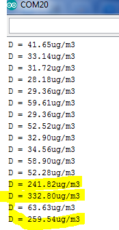
(yellow marked is smoke test).Then I've applied following sketch:
// Enable debug prints
#define MY_DEBUG

// Enable and select radio type attached
#define MY_RADIO_NRF24
//#define MY_RADIO_RFM69

#include <SPI.h>
#include <MySensors.h>

#define CHILD_ID_DUST 0
#define DUST_SENSOR_ANALOG_PIN 1
#define DUST_SENSOR_DIGITAL_PIN 3

const int numreadings = 60;

unsigned long SLEEP_TIME = 1000;

int val = 0;
float valDUST =0.0;
float lastDUST =0.0;
int samplingTime = 280;
int deltaTime = 40;
int sleepTime = 9680;
float voMeasured = 0;
float calcVoltage = 0;
float dustDensity = 0;

MyMessage dustMsg(CHILD_ID_DUST, V_LEVEL);

void setup(){
  pinMode(DUST_SENSOR_DIGITAL_PIN,OUTPUT);
}

void presentation() {
  // Send the sketch version information to the gateway and Controller
  sendSketchInfo("Dust Sensor", "1.0");

  // Register all sensors to gateway (they will be created as child devices)
  present(CHILD_ID_DUST, S_DUST);
}

void loop() {
  float cumsum = 0;
  float temp = 0;
 // float temp1 = 0;
 // float cum_density = 0;
  for (int sample = 0; sample < numreadings; sample ++){
  digitalWrite(DUST_SENSOR_DIGITAL_PIN,LOW); // power off the LED
  delayMicroseconds(samplingTime);
  uint16_t voMeasured = analogRead(DUST_SENSOR_ANALOG_PIN);// Get DUST value
  delayMicroseconds(deltaTime);
  digitalWrite(DUST_SENSOR_DIGITAL_PIN,HIGH); // turn on the LED
  // 0 - 5V mapped to 0 - 1023 integer values
  // recover voltage
  temp = voMeasured * (5.0 / 1024.0);
  cumsum = cumsum + temp;// cumulative sum over 60 seconds
  delay(500);
  Serial.print("Raw Signal Value (0-1023): ");
  Serial.print(voMeasured);
  Serial.print(" - Voltage: ");
  Serial.print(calcVoltage);
  Serial.print(" - Dust Density: ");
  Serial.println(dustDensity);
  }

  // linear eqaution taken from http://www.howmuchsnow.com/arduino/airquality/
  // Chris Nafis (c) 2012
  dustDensity = (0.17 * cumsum - 0.1)* (1000/60);


  Serial.print(" - Dust Density: ");
  Serial.println(dustDensity); // unit: ug/m3

  send(dustMsg.set((int)ceil(dustDensity)));

  sleep(SLEEP_TIME);
}
and the output is:
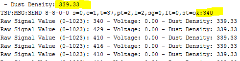
In Domoticz it looks:
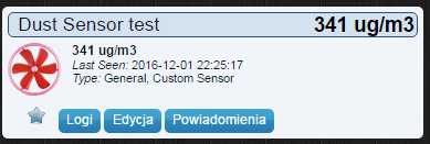
It seems that my room air polution is super high :), but, it isn't :)
Ideas, what should be changed in the code?
Best,
-
Wall mounted 'mood light' v2FIXED!
Happy :)Issue was so obvious...
I was supplying Neopixel LED's with 5V trought Arduino pro mini... so when node was starting everything was ok till sending light pattern to node. When data was send, LED's took to much Watts, and radio was crashing...
So now I just powered LED's with 5V parerall to the node ( LED's are supplied before node).Now, I need to understand your code, how "buttonPin" is working and how to set patterns. It seems that the code is acting wired sometimes, but I think that's due to my less knowledge about it now.
Thanks for guidlines!
-
Wall mounted 'mood light' v2@AWI
I've tried to be detailed :)
Ok, here's how my radio and connections looks like:
Power suplly (5V, 3A) goes to RPi3 --> USB --> Arduino Uno gateway with radio (NRFL01+PA+LNA with 4,7uF 16V capacitor. Radio powered from 3,3V arduino pin). I've also tried with non amplified radio - the same result:(
3 devices (incl. gateway) connected via USB to RPi3. I've boosted current on RPi3 USB ports to 1,2A, by adding line:max_usb_curent=1to /boot/config.txt, but that didn't change anything.
Node is pro mini 5V, Radio NRFL01 has 4,7uF capacitor and 3,3 power supply goes from step-down regulator.
My other nodes (1 wire temp, lux metter, relay, DHT sensor) are working when connected without disturb.
For examlpe when I set:
Then RGB color is send to node, but after a while I canno't do anything more (communication crashes) and I got a lot of:
!TSP:MSG:PVER mismatch
TSP:MSG:READ 0-0-28 s=1,c=1,t=3,pt=0,l=0,sg=0:
Any advice will be apriciate
-
Wall mounted 'mood light' v2Hello AWI,
great stuff!, you inspired my by posting this article to build similiar mood light.
for LED I've used ring 16 x LED ws2812b 5V neopixel.
Wiring:
"stripPin = 5" is connected to pin 4 on LED, which is "DIN - Control data signal input"Sketch used from this post. While compiling, I got following warnings, but think that that they should't cause a problem:
In file included from C:\Users\Jon\Documents\Arduino\libraries\FastLED/platforms/avr/fastled_avr.h:4:0,
                 from C:\Users\Jon\Documents\Arduino\libraries\FastLED/platforms.h:27,
                 from C:\Users\Jon\Documents\Arduino\libraries\FastLED/FastLED.h:52,
                 from C:\Users\Jon\Documents\Arduino\MySensors-Mood_light_v2.ino\MySensors-Mood_light_v2.ino.ino:55:
C:\Users\Jon\Documents\Arduino\libraries\FastLED/fastled_delay.h:37:0: warning: "NOP" redefined

 #  define NOP __asm__ __volatile__ ("cp r0,r0\n");

 ^

In file included from C:\Users\Jon\Documents\Arduino\libraries\MySensors/drivers/RF24/RF24.cpp:23:0,
                 from C:\Users\Jon\Documents\Arduino\libraries\MySensors/MySensors.h:242,
                 from C:\Users\Jon\Documents\Arduino\MySensors-Mood_light_v2.ino\MySensors-Mood_light_v2.ino.ino:53:
C:\Users\Jon\Documents\Arduino\libraries\MySensors/drivers/RF24/RF24.h:144:0: note: this is the location of the previous definition

 #define NOP             0xFF

 ^
In file included from C:\Users\Jon\Documents\Arduino\MySensors-Mood_light_v2.ino\MySensors-Mood_light_v2.ino.ino:55:0:

C:\Users\Jon\Documents\Arduino\libraries\FastLED/FastLED.h:17:21: note: #pragma message: FastLED version 3.001.003

 #    pragma message "FastLED version 3.001.003"

                     ^
Here's my node output from serial monitor:
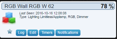
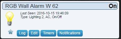
Starting sensor (RNNNA-, 2.0.0)
TSM:INIT
TSM:RADIO:OK
TSP:ASSIGNID:OK (ID=62)
TSM:FPAR
TSP:MSG:SEND 62-62-255-255 s=255,c=3,t=7,pt=0,l=0,sg=0,ft=0,st=bc:
TSP:MSG:READ 0-0-62 s=255,c=3,t=8,pt=1,l=1,sg=0:0
TSP:MSG:FPAR RES (ID=0, dist=0)
TSP:MSG:PAR OK (ID=0, dist=1)
TSM:FPAR:OK
TSM:ID
TSM:CHKID:OK (ID=62)
TSM:UPL
TSP:PING:SEND (dest=0)
TSP:MSG:SEND 62-62-0-0 s=255,c=3,t=24,pt=1,l=1,sg=0,ft=0,st=ok:1
TSP:MSG:READ 0-0-62 s=255,c=3,t=25,pt=1,l=1,sg=0:1
TSP:MSG:PONG RECV (hops=1)
TSP:CHKUPL:OK
TSM:UPL:OK
TSM:READY
TSP:MSG:SEND 62-62-0-0 s=255,c=3,t=15,pt=6,l=2,sg=0,ft=0,st=ok:0100
TSP:MSG:SEND 62-62-0-0 s=255,c=0,t=17,pt=0,l=5,sg=0,ft=0,st=ok:2.0.0
TSP:MSG:SEND 62-62-0-0 s=255,c=3,t=6,pt=1,l=1,sg=0,ft=0,st=ok:0
TSP:MSG:READ 0-0-62 s=255,c=3,t=6,pt=0,l=1,sg=0:M
TSP:MSG:SEND 62-62-0-0 s=255,c=3,t=11,pt=0,l=17,sg=0,ft=0,st=ok:AWI RGB Wall W 62
TSP:MSG:SEND 62-62-0-0 s=255,c=3,t=12,pt=0,l=3,sg=0,ft=0,st=ok:2.0
TSP:MSG:SEND 62-62-0-0 s=1,c=0,t=26,pt=0,l=17,sg=0,ft=0,st=ok:RGB Wall RGB W 62
TSP:MSG:SEND 62-62-0-0 s=0,c=0,t=3,pt=0,l=19,sg=0,ft=0,st=ok:RGB Wall Light W 62
TSP:MSG:SEND 62-62-0-0 s=2,c=0,t=3,pt=0,l=25,sg=0,ft=0,st=ok:RGB Set Solid color (text
TSP:MSG:SEND 62-62-0-0 s=3,c=0,t=36,pt=0,l=23,sg=0,ft=0,st=ok:RGB Wall textcolor W 62
TSP:MSG:SEND 62-62-0-0 s=4,c=0,t=3,pt=0,l=19,sg=0,ft=0,st=ok:RGB Wall Alarm W 62
TSP:MSG:SEND 62-62-0-0 s=5,c=0,t=4,pt=0,l=21,sg=0,ft=0,st=ok:RGB Wall Pattern W 62
No registration required
Init complete, id=62, parent=0, distance=1, registration=1
Everything seems to be ok. For controller I use Domoticz, devices where discovered and added to controller .
Later on, on serial monitor I got:
TSP:MSG:SEND 62-62-0-0 s=255,c=3,t=22,pt=5,l=4,sg=0,ft=0,st=ok:57916
TSP:MSG:SEND 62-62-0-0 s=255,c=3,t=22,pt=5,l=4,sg=0,ft=0,st=ok:117917
.....
When I press the button I got:
TSP:MSG:SEND 62-62-0-0 s=0,c=1,t=2,pt=2,l=2,sg=0,ft=0,st=ok:1When pressed once more I got:
TSP:MSG:SEND 62-62-0-0 s=0,c=1,t=2,pt=2,l=2,sg=0,ft=0,st=ok:0Problem is, that later nothing happens (after shortly pressing the button - pin 4)
Only, when I press in Domoticz the leds starts to blink white/red in pulse mode (so wiring is ok?)
on serial monitor I got: ("st=fail:1"It's displayed 10 times)
TSP:MSG:READ 0-0-62 s=4,c=1,t=2,pt=0,l=1,sg=0:1
TSP:MSG:ACK msg
TSP:MSG:SEND 62-62-0-0 s=4,c=1,t=2,pt=0,l=1,sg=0,ft=0,st=ok:1
Sensor: 4
 Color: - Brightness: 127
TSP:MSG:READ 0-0-62 s=4,c=1,t=2,pt=0,l=1,sg=0:1
TSP:MSG:ACK msg
!TSP:MSG:SEND 62-62-0-0 s=4,c=1,t=2,pt=0,l=1,sg=0,ft=0,st=fail:1
Sensor: 4
Later i got a looot of times:
!TSM:UPL FAIL, SNP
TSM:FPAR
TSP:MSG:SEND 62-62-255-255 s=255,c=3,t=7,pt=0,l=0,sg=0,ft=0,st=bc:
TSP:MSG:READ 0-0-62 s=4,c=1,t=2,pt=0,l=1,sg=0:1
TSP:MSG:ACK msg
!TSP:SEND:TNR
Sensor: 4
 Color: - Brightness: 127
TSP:MSG:READ 0-0-62 s=4,c=1,t=2,pt=0,l=1,sg=0:1
TSP:MSG:ACK msg
!TSP:SEND:TNR
Sensor: 4
and @the end it seems that node stop responding:
!TSM:FPAR:FAIL
!TSM:FAILURE
TSM:PDT
TSM:INIT
When I press the button (pin 4) few times, long/short, then I got some random patterns, but node seems to be crashed and canno't be controlled from Domoticz.
I apriciate any kind of your supprot in my case.
Best