Navigation

    • Register
    • Login
    • OpenHardware.io
    • Categories
    • Recent
    • Tags
    • Popular
    1. Home
    2. blacey
    3. Best
    • Profile
    • Following
    • Followers
    • Topics
    • Posts
    • Best
    • Groups

    Best posts made by blacey

    • IR Blaster (progress)

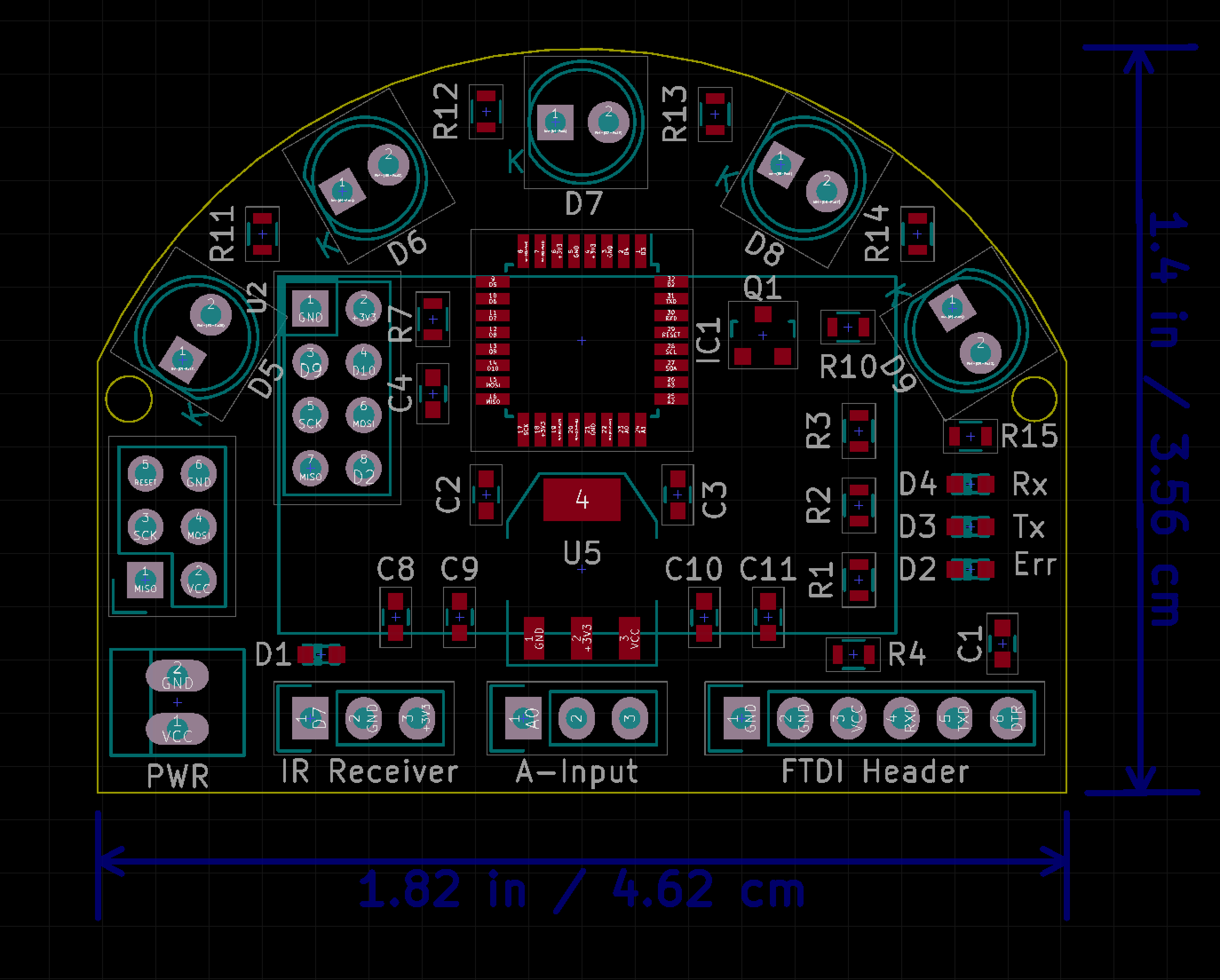
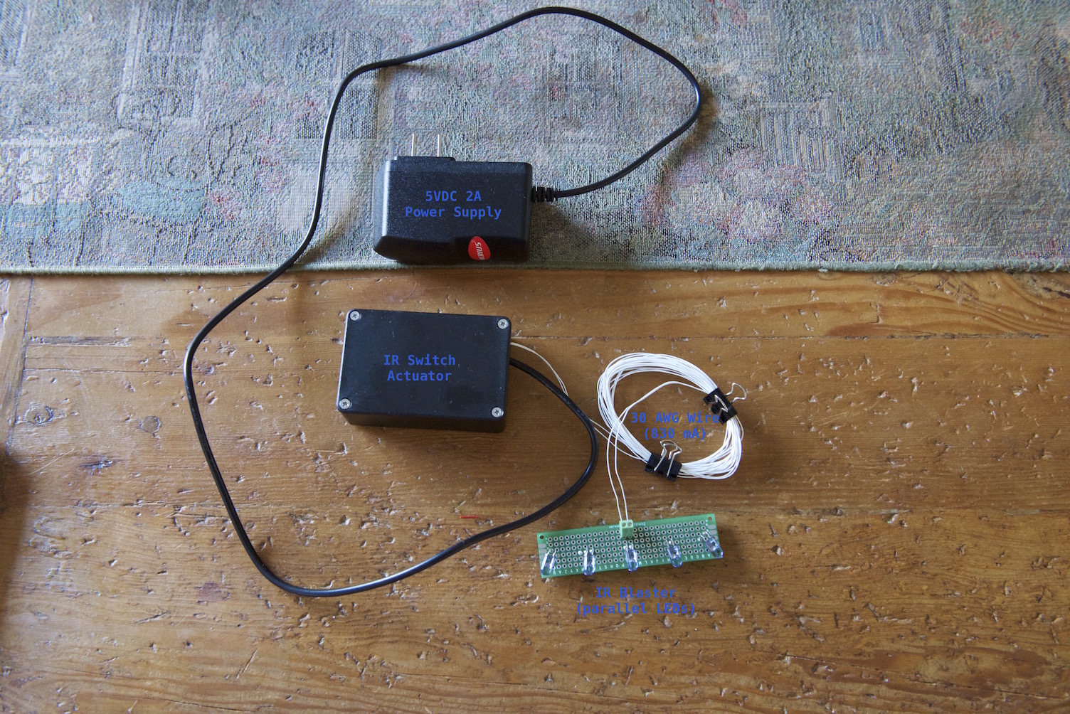
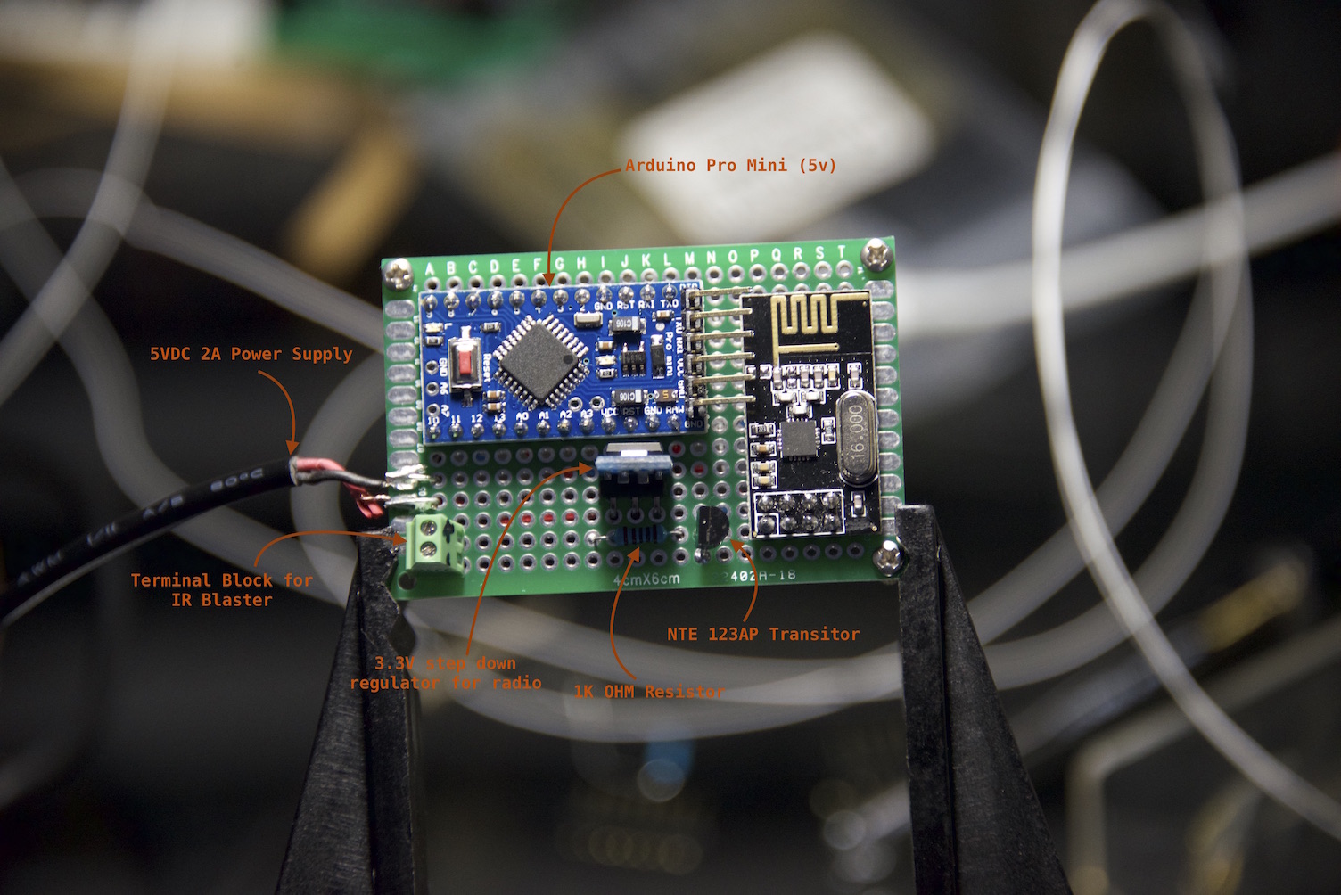
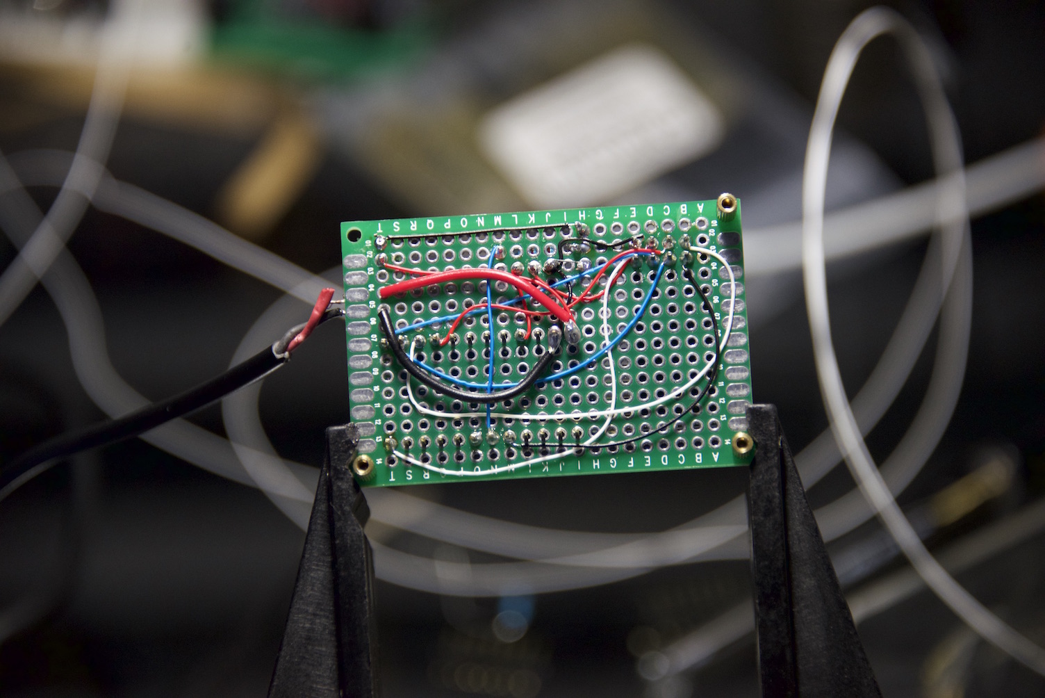
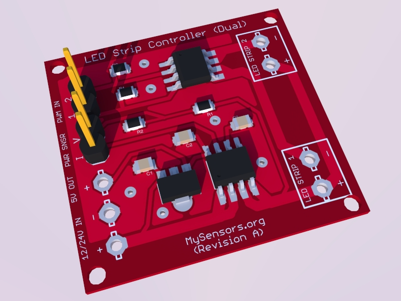
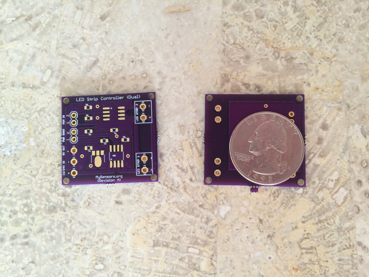
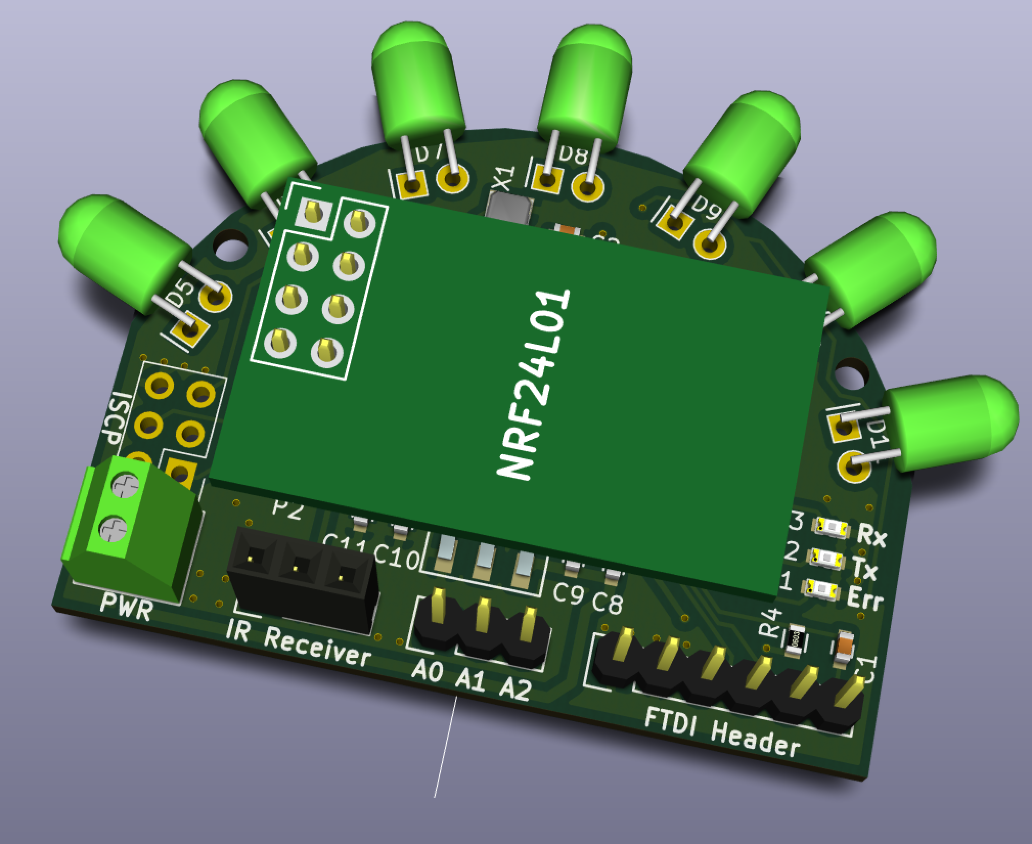
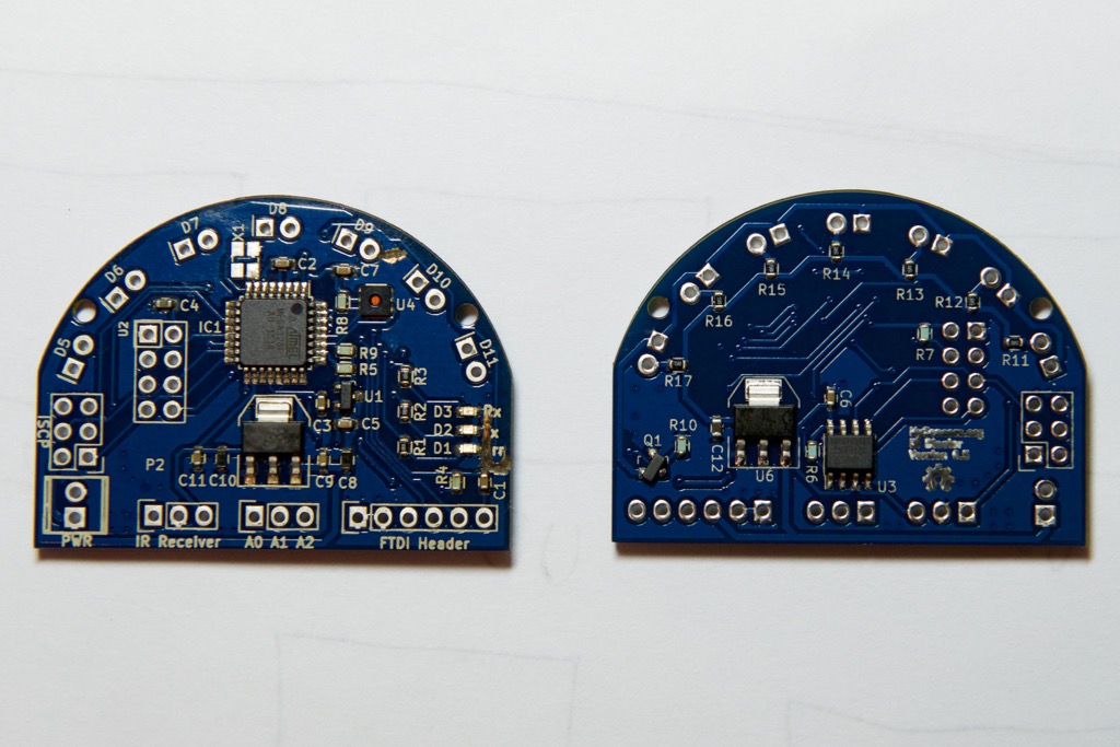
      Several people have requested the IR Blaster that I demonstrated in this this Luminara Candle Actuator post but the 1st generation IR Blaster is tedious to build by hand so I decided to develop a purpose-built IR Blaster Actuator. The concept is to collapse everything from the 1st generation IR blaster down to a single PCB that also incorporates all the MySensor's capabilities (e.g. OTA sketch updates and hardware message-signing), add a temperature and humidity sensor (why not?), and a high-luminance, long-range IR Blaster all powered by a standard 5VDC AC power adapter. The IR Blaster can be used to control multiple devices in your home that use a standard infrared remote control (e.g. TV, Receiver, DVR, Air Conditioner, Luminara candles, etc.). Below is an overview, the initial schematic and a rough board layout to give you a sense of the design and size. In discussing with @Hek, if there is enough interest, we will offer this board on ITead Studio so if you are interested, please weigh in and more importantly blast away (pun intended) with critiques or flaws in the features, design, etc.

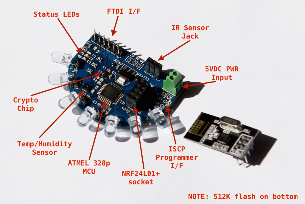
      MySensors Core (derivative work of @tobowmo's Sensebender Micro who deserves a ton of credit and huge thanks for this circuit!)

      • ATMEL MCU - ATMEGA 328P / Arduino compatible
      • Hardware encryption for message signing - ATSHA204A (thanks to @Anticimex for developing the message signing support)
      • Flash for OTA sketch updates - AT25F512C (thanks to @tosa and @tekka for the OTA sketch support)
      • Radio - NRF24L01+ socket
      • 3.3 VDC on-board LDO voltage regulator to power MySensors MCU & Radio Core

      Actuators

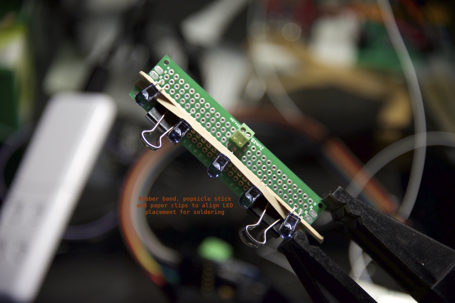
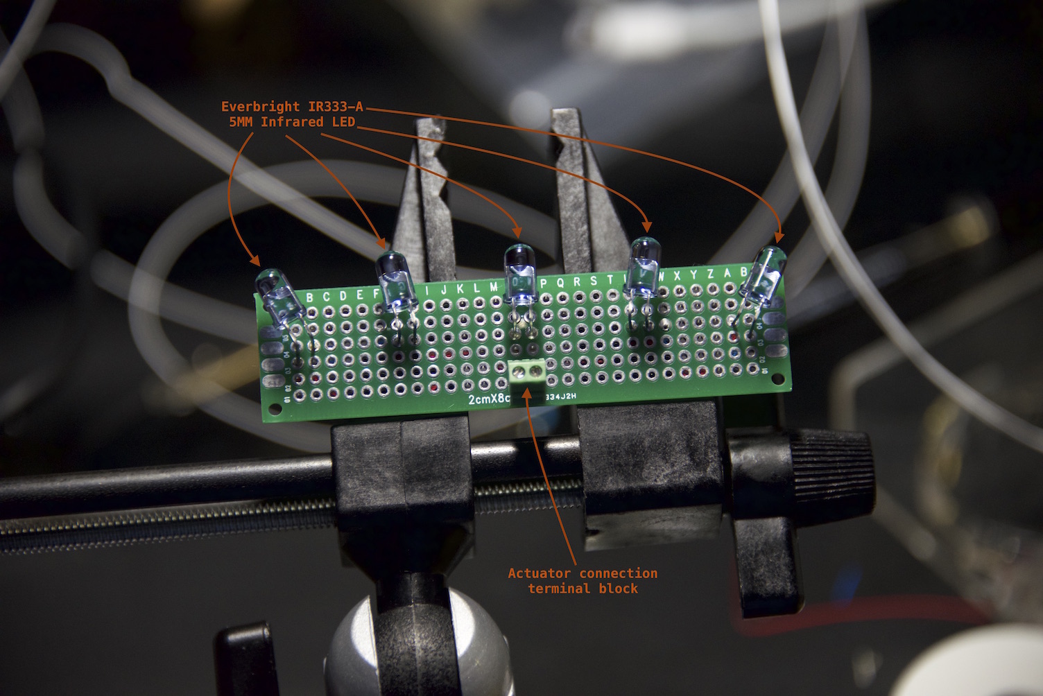
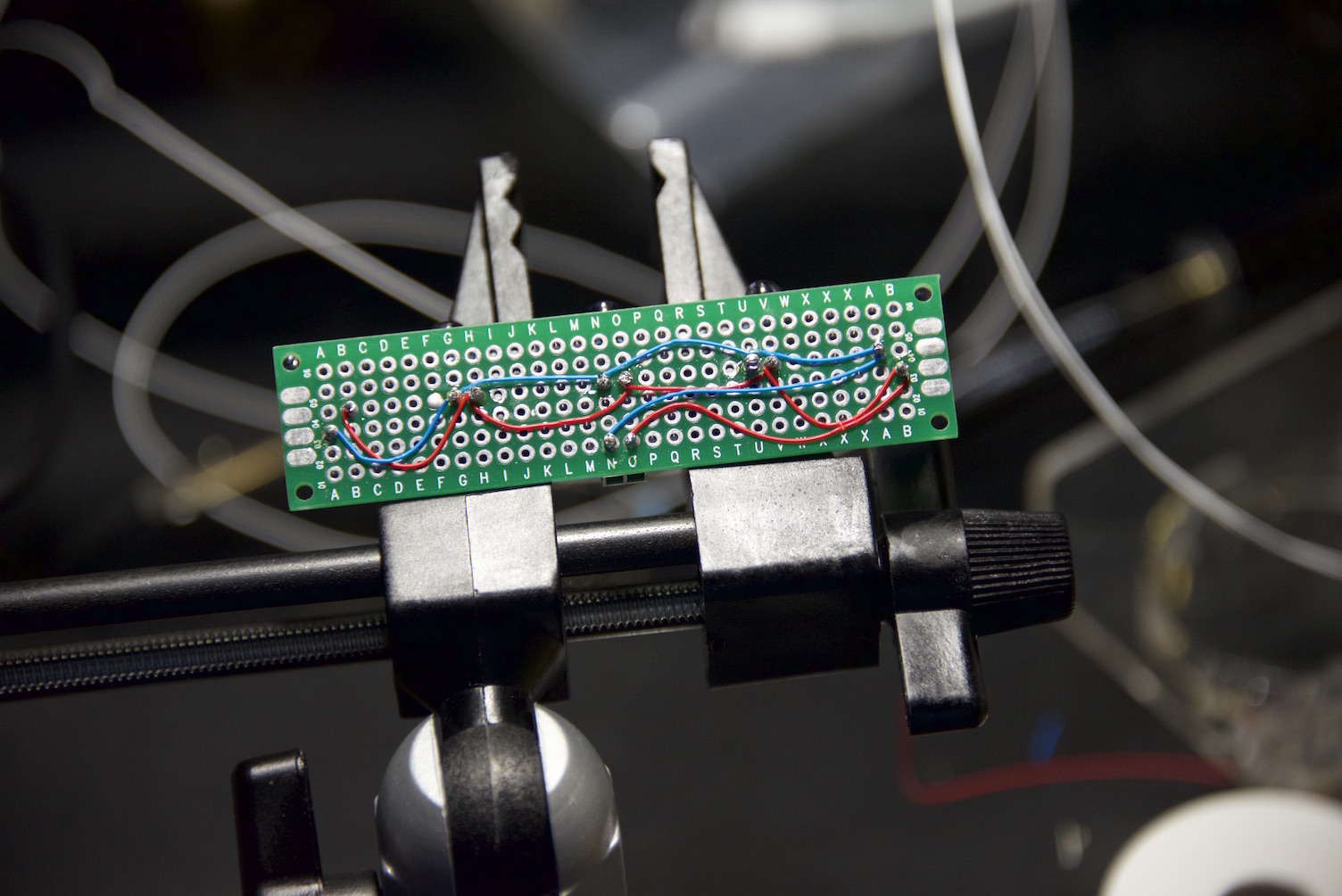
      • High-Luminance IR Blaster (5 IR LEDs)
      • Driven by logic-level MOSFET for maximum current distribution to IR LEDs
      • Separate 5.0 VDC on-board LDO voltage regulator to power IR blaster (Isolate MySensors Core from IR current dips)
      • 180 degree illumination

      Sensors

      • IR receiver socket (can be used for IR decoding for sketch customization)
      • Temperature and Humidity (Si7021 - same sensor that Thomas MΓΈrch selected for the Sense-Bender Micro)

      3 Analog Inputs

      • A0, A1, A2 (auxiliary input for other sensors - e.g. PIR, luminance, etc.)

      Other

      • Rx, Tx, and Err LEDs (credit to @thozza for adding LED support to sensors/actuators)

      Power

      • list itemStandard 5VDC adapter (regulated on board to 3.3V)

      Open questions

      • IR LED choice - range versus luminance spread (IR-333-A vs. IR-333-C or hybrid)
      • Include an external oscillator/crystal
      • Decoupling capacitor value for NRF24L01+
      • Include barrel connector to simultaneously drive external IR LED emitters
      • Physical learn-mode trigger
      • (added) Driving 5 IR LEDs at maximum luminance with a single transistor (will breadboard to confirm)
      • (added) Include a 5V power plane

      Schematic v0.2.pdf
      IRBlasterBoard v0.1.png

      posted in Hardware
      blacey
      blacey
    • IR Switch for Luminara Candle Automation (repost with video, photos and final sketch)

      So, my wife loves her Luminara candles that she can turn on and off with a Luminara remote control so heck, why not tie them into the HA system so they come on at sunset and go off when we go to bed each evening? I built a high-power IR blaster, ginned up a small circuit to decode the Luminara remote control codes using the IRSensor sketch MySensors example provided by @hek, configured the on/off IR codes in the actuator sketch and voila - our Vera 3 is able to control my wife's candles! Video, photos and the sketch are provided below.

      IR Switch Video

      Completed IR Switch Actuator
      FinalIRSwitch.jpg

      IR Switch Actuator Circuit (top)
      IRSwitchActuatorTop.jpg

      IR Switch Actuator Circuit (bottom) - should probably invest in the convenience boards that others have created to avoid excessive wire-wrapping and soldering πŸ˜‰
      IRSwitchActuatorBottom.jpg

      Assembling the IR Blaster - parallel circuit, no forward current resistors to maximize radiant luminance.
      IRBlasterAssemblyTop.jpg

      Assembled IR Blaster (top)
      IRBlasterTop.jpg

      Assembled IR Blaster (bottom)
      IRBlasterBottom.jpg

      IR Switch Sketch

      This was a fun project with a very positive wife factor and I hope others find this useful.

      Cheers.

      UPDATE (2015-MAY-13) I have started a new thread here to flesh out the design of an official IR Blaster -

      posted in My Project
      blacey
      blacey
    • RE: Problem Connecting to gateway

      @Jaime-Machado said in Problem Connecting to gateway:

      Can anyone tell me whats wrong here?

      Welcome to MySensors! Sounds like you are making great strides already. Usually the gateway is connected to an HA controller that is responsible for vending IDs to nodes during the inclusion/pairing process. In your case, if you are using a stand-alone gateway and node, then you will need to statically define the node id in the node sketch. The node id needs to be unique to each node and ranges from 1 to 254 (note, you can also have up to 254 child sensors per node).

      Try setting the following in the top of your node sketch before the MySensors.h include.

      #define MY_NODE_ID 1
      
      #include <MySensors.h>
      

      Whenever I need to statically set a node id, I usually do so at the very top of the sketch so it is clear when you open the sketch that the node id is statically defined.

      Finally, did you know that you can post code blocks using ``` before and after the code to make it more legible? That is what I used above.

      posted in Troubleshooting
      blacey
      blacey
    • RE: Reflow Oven

      Here are some of the results that I achieved with a built-from-scratch reflow oven and Peter's ControLeo.

      MySensors.org Dual Channel LED Strip PWD Dimmer with current sensing (voltage, amperes with computed wattage):

      pcb-render.jpg

      Proto-boards from OSHPark

      pcb.jpg

      Oven build images...

      OvenInternals.jpg

      OvenInternals1.jpg

      First board baking...

      BakingFirstBoard.jpg

      Temperature profile I achieved for first board.

      profile.png

      Fully functional test board.

      testboard.jpg

      This final product will be refined and will vary slightly but @hek, @axillent and I plan to make boards like this and more available, once the designs are fully baked so to speak. In the mean time, these simple reflow ovens based upon the ControLeo work very well.

      posted in Hardware
      blacey
      blacey
    • RE: IR Blaster (progress)

      First Dev Boards Complete 10-JUL-2015 - status update with video

      I assembled two dev boards yesterday, brought up all subsystems and they are both working great. Still a bit more work to do before they go to production but here are a couple of photos and a demonstration video.

      Assembled dev board w/o radio
      DSC_1131.jpg

      Assembled board w/Radio attached
      DSC_1132.jpg

      Demonstration Video
      https://youtu.be/UXjcwlJOMOI

      I am going to rev the board a bit to pull all components to the top-side to reduce the cost and also subject the boards to the IR Sensor Array testing to tune the IR LED component choice for maximum performance.

      posted in Hardware
      blacey
      blacey
    • RE: Invert the relay in the sketch

      @derksuh Ok, I took a shot at refactoring your sketch. I didn't have much time and I only ensured that it compiles so your MMV... This could probably be simplified even more but you know the old saying, "If I had more time, I would write less code" πŸ˜‰

      #define MY_DEBUG
      #define MY_RADIO_NRF24
      #define MY_REPEATER_FEATURE
      #define MY_NODE_ID 1
       
      #include <SPI.h>
      #include <MySensors.h>
      #include <DHT.h>
      
      // Set this to the pin you connected the DHT's data pin to
      #define DHT_DATA_PIN 6
      
      // Set this offset if the sensor has a permanent small offset to the real temperatures
      #define SENSOR_TEMP_OFFSET 0
      
      // Sleep time between sensor updates (in milliseconds)
      // Must be >1000ms for DHT22 and >2000ms for DHT11
      static const uint64_t UPDATE_INTERVAL = 60000;
      
      // Force sending an update of the temperature after n sensor reads, so a controller showing the
      // timestamp of the last update doesn't show something like 3 hours in the unlikely case, that
      // the value didn't change since;
      // i.e. the sensor would force sending an update every UPDATE_INTERVAL*FORCE_UPDATE_N_READS [ms]
      static const uint8_t FORCE_UPDATE_N_READS = 10;
      
      #define CHILD_ID_HUM 0
      #define CHILD_ID_TEMP 1
      #define CHILD_ID_RLAY 2
      
      #define RELAY_PIN  3
      #define RELAY_ON 1  
      #define RELAY_OFF 0
      
      #define TEMP 0
      #define HUMI 1
      
      byte state = 0;
      bool metric = true;
      
      MyMessage msgHum(CHILD_ID_HUM, V_HUM);
      MyMessage msgTemp(CHILD_ID_TEMP, V_TEMP);
      MyMessage msgRlay(CHILD_ID_RLAY, V_STATUS);
      
      typedef struct {
        float last;
        uint8_t nNoUpdates;
      } sensorState_t;
      
      sensorState_t dhtState[2];
      
      DHT dht;
      
      void presentation()   
      { 
        // Send the sketch version information to the gateway
        sendSketchInfo("TempHumidRelay", "1.1");
        
        // Register all sensors to gw (they will be created as child devices)
        present(CHILD_ID_HUM, S_HUM);
        present(CHILD_ID_TEMP, S_TEMP);
        present(CHILD_ID_RLAY, S_BINARY);
      
        // Ask the gateway for the units of measure to use
        metric = getConfig().isMetric;
      }
      
      void setup()
      {
        // Make sure relays are off when starting up
        pinMode(RELAY_PIN, OUTPUT);
        digitalWrite(RELAY_PIN, RELAY_OFF);
      
        // Initialize the Temperature & Humidity sensor, first reading will be sent from loop()
        if (UPDATE_INTERVAL >= dht.getMinimumSamplingPeriod()) {
          dht.setup(DHT_DATA_PIN); // set data pin of DHT sensor and model (e.g. DHT_22, DHT_11)
        } else {
          Serial.println("Warning: UPDATE_INTERVAL is smaller than supported by the sensor!");
          Serial.println("Increase UPDATE_INTERVAL and re-upload sketch...");
        }
       
        // Request the latest relay status from the gateway 
        Serial.println("Requesting initial value from controller");
        request(CHILD_ID_RLAY, V_STATUS);
      }
      
      void loop()      
      { 
        // Sleep until next valid interal to read temperature and humidity
        wait(UPDATE_INTERVAL);
      
        // Read current temperature & humidity from DHT22
        dht.readSensor(true);
        float temperature = dht.getTemperature();
      
        // Only send temperature if it has changed since the last measurement or if we didn't send an update for n times
        if (temperature != dhtState[TEMP].last || dhtState[TEMP].nNoUpdates >= FORCE_UPDATE_N_READS) {
          dhtState[TEMP].last = temperature;
          temperature = metric ? temperature : dht.toFahrenheit(temperature);
          temperature += SENSOR_TEMP_OFFSET;
          send(msgTemp.set(temperature, 1));
          #ifdef MY_DEBUG
            Serial.print("T: ");
            Serial.println(temperature);
          #endif
          dhtState[TEMP].nNoUpdates = 0;
        }
        else if (isnan(temperature)) {
          Serial.println("Failed reading temperature from DHT!");
        } else {
          // Increase no update counter if the temperature stayed the same
          dhtState[TEMP].nNoUpdates++;
        }
      
        // Retrieve the current humidity
        float humidity = dht.getHumidity();
      
        // Only send humidity if it changed since the last measurement or if we didn't send an update for n times
        if (humidity != dhtState[HUMI].last || dhtState[HUMI].nNoUpdates >= FORCE_UPDATE_N_READS) {
          dhtState[HUMI].last = humidity;
          send(msgHum.set(humidity, 1));
          
          #ifdef MY_DEBUG
            Serial.print("H: ");
            Serial.println(humidity);
          #endif
          dhtState[HUMI].nNoUpdates = 0;
      
        } else if (isnan(humidity)) {
          Serial.println("Failed reading humidity from DHT");
        } else {
          // Increase no update counter if the humidity stayed the same
          dhtState[HUMI].nNoUpdates++;
        }
      }
      
      void receive(const MyMessage &message) {
        Serial.println("Received message...");
      
        if (message.type == V_STATUS) {
          // Change relay state
          state = message.getByte();
          digitalWrite(RELAY_PIN, state);
          send(msgRlay.set(state));
        }
      }
      
      posted in Development
      blacey
      blacey
    • RE: IR Blaster (progress)

      @gloob, @john, @notYetRated and everyone else - Here is an update on IR Blaster project

      The first dev boards are working well but not as good as they should IMHO. My 0.5 LED circuit design uses a separate voltage-regulated parallel IR LED emitter circuit. After a lot of technical research into the depths of IR Emitters and collaboration with others, I can greatly improve the IR performance by moving to a constant-current (not constant-voltage) serial IR LED emitter circuit. I have been scouring the net for constant current regulators and/or LED drivers that can handle 7 IR LEDs @100ma & 1.6FV and have a few candidates under review for prototyping.

      I have also been in touch with the AnalysisIR guys to ensure compatibility of our board with their offerings because users have successfully decoded long IR encodings, using the advanced AnalysisIR decoding software, such as HVAC units popular in the EU/UK - for example Panasonic AC and Mitsubishi AC. The goal being that any Analysis IR decodes, will be directly compatible with our board so we can leverage the enthusiasm and prior work of the AnalysisIR community at large. In addition, I would like to advance our board to be able serve as a full spectrum IR decoder to ensure maximum decoding performance when using AnalysisIR on the board. Compatibility requires running the MCU at 16MHz or great to improve the IR mark/space decoding which also requires additional changes to the original circuit design.

      All of that said, the reason for the recent silence by me has been due to my personal life - I have had a hectic family pursuit requiring multi-month travel from home and work has heated up again.

      Fear not though, this is an extremely important project for me and I will get it done! While it is taking a bit longer than I had hoped, I firmly believe it will be well worth the wait.

      posted in Hardware
      blacey
      blacey
    • RE: IR Blaster (progress)

      Apologies everyone but progress has been much slower than I had planned/wished for two reasons. 1) Work obligations and 2) a special automation from my wife that has usurped my MySensors cycles that required helping the FreeCAD open source project to advance my cause. My plan is to hit IR Blaster hard within the next 4-6 weeks.

      posted in Hardware
      blacey
      blacey
    • RE: SmartThings integration?

      A good friend of mine and talented engineer/architect recently purchased a SmartThings hub. Last weekend I ginned up an ESP8266/Node MCU gateway paired with a SenseBender Micro and gave it to him for SmartThings integration experimentation/plug-in development - I'm hopeful that something good will come of it πŸ˜‰

      posted in Feature Requests
      blacey
      blacey
    • RE: Sending image-data over the MySensors network.

      @Oitzu said:

      Hm... i see. I thought there could be maybe a hidden functionallity to directly pipe and stream it trough the MySensors network.
      But this could work as well, i just need to chomp it up and puzzle it together on the other side.

      Or you could add a new streaming API to the core and create a pull-request πŸ˜‰

      posted in Development
      blacey
      blacey
    • RE: I can't get it to work (Nano V3.0, NRF24L01+Z)

      @mfalkvidd said:

      However, it looks like the header pins have not been soldered to the Nano.

      Good eyes and nice catch πŸ˜‰

      posted in Troubleshooting
      blacey
      blacey
    • RE: IR Blaster (progress)

      Placed an order for the first prototype boards today... Sourcing from China to U.S. so it will take a while for them to arrive from the fab but I will keep everyone apprised of the progress. That said, here is a render of the protoboard (v0.5) with NRF24L01+ attached to provide a sense of the board's physical size/footprint (thanks to @tbowmo for the NRF24L01+ 3d-shape).

      Screen Shot 2015-06-25 at 4.32.36 PM.png

      posted in Hardware
      blacey
      blacey
    • RE: Anyone tried the $199 Monoprice 3D printer?

      @NeverDie Anything other than ABS can be printed inside. ABS gives of odor and can adversely affect some people's respiratory systems.

      posted in Enclosures / 3D Printing
      blacey
      blacey
    • RE: Powering mote 24/7 using only a supercap and solar

      @NeverDie And bootchk designed it using KiCAD - well done! As a side note, in the very early days of the MySensors core team (@hek, @tbowmo, @Anticimex and I) decided that, in the spirit of open source, to abandon commercial / proprietary CAD programs for the MySensors official board designs, hence why SenseBender Micro is in KiCAD and the forthcoming gateway will be too. We wanted to ensure that all board designs would be available to users freely for modification and improvements. While KiCAD is the standard for the official MySensors board designs, it would be nice to see broader adoption by the MySensors community as well (as I step down from my soapbox) πŸ˜‰

      posted in My Project
      blacey
      blacey
    • RE: Issue after updating from 1.5 to 2.1.1

      @tarends120

      @tekka optimized the NRF driver significantly between release 1.5.1 and 2.1.1 allowing the driver to push the radio a bit harder resulting in higher current-draw spikes. I experienced the same issue with nodes that had been running for several years but failing miserably after simply upgrading to the newer library. What I had to do was ensure that I had an adequate current supply for the radio to cope with the larger current-draw spikes. This included adding a 47uf capacitor across the NRF VCC and GND pin (actually @tekka recommended 100uf) and in one case swapping out a 3.3v LDO for a higher current LDO. So I would suggest that you first eliminate NRF power/current supply issues first. Additional background about NRF power needs are available here - https://arduino-info.wikispaces.com/Nrf24L01-2.4GHz-HowTo#PP

      By the way, the new MySensors Gateway that @tbowmo developed has no problem driving an NRF24L01+ PL/NA+ radio at high power.

      posted in Troubleshooting
      blacey
      blacey
    • RE: IR Blaster (progress)

      Status Update - 2015-07-10

      Ok, so here is the latest on our progress to build an IR Blaster v0.5 first prototype/dev board. I have assembled two dev boards that pass the initial smoke test of power regulation, MCU and status LEDs. Through this process, I have identified a number of changes and improvements to the board none of which blocks bringing up a fully functioning IR blaster (at least not yet so keep fingers crossed). I did find one KiCad Gerber bug that shorted the MOSFET gate trace to the upper ground plane but with an Exacto knife and a little elbow grease, I was able to eliminate the short - if you look closely around D10 and the Err LED, you sill see my handy work πŸ˜‰

      Photo of the twin v0.5 dev boards.

      Left is top-side board #1 and right is bottom-side board #2
      DSC_1097.jpg

      Short video excerpt of the smoke test running (luckily, without smoke)

      And here is a short video clip of the first board passing initial smoke test proving that the power regulation, MCU and status LEDs are working per design.

      IR Blaster v0.5 Smoke Test

      Next steps (dev prototype v0.5)

      • Verify the off-MCU flash and crypto chip electrical and functional integrity by extending the smoke test sketch to run @tbowmo and @patrick SenseBender Micro built-in tests.
      • Verify the NRF24L01+ electrical and functional integrity - solder socket to board and confirm that the radio comes up with MySensors library
      • Verify MySensors full-functionality - load the latest SenseBender Micro sketch and confirm reporting of humidity and temperature. With the proper MySensors library, the sensor Tx, Rx, and Err LEDs should provide send and receive status accordingly.
      • Verify IR LED circuit by soldering 7 IR LEDs to the board and confirming electrical and functional integrity

      Bottom-line, quite a bit of work left to do but no major blockers encountered so far using two initial dev boards.

      posted in Hardware
      blacey
      blacey
    • RE: [SOLVED] Raspberry Pi Gateway to Vera UI7 Not adding sensors

      @anvil - great code sleuthing! I have been absent due to travel but to ensure this doesn't slip through the cracks and create future confusion for other users, I have filed GitHub issue https://github.com/mysensors/MySensors/issues/770 to add these defaults into the RPI gateway example for the 2.2.0 release.

      With your increased familiarity with the code base, feel free to make the change and submit a GitHub PR if you are so inclined, otherwise it will wait until one of the core members makes the change.

      posted in Troubleshooting
      blacey
      blacey
    • RE: Gateway not working on VeraLite + UI6 - No Serial Port configuration available

      @cdrum Try this - http://forum.mysensors.org/topic/269/lost-usb-serial-port-connection-on-vera-3-again/8

      posted in Vera
      blacey
      blacey
    • RE: Dimmer sensor

      @boblasure So you effectively want 3 children, one for each PWM? You will need to extend the sketch to handle two additional pins/children. @korttoma has already done the work...

      Here is his sketch that handles four channels.

      https://codebender.cc/sketch:44740

      posted in Development
      blacey
      blacey
    • RE: Reflow Oven

      I bought this oven for $25.00. Cheap and works great. Added a 3rd burner for $10 off eBay.

      I captured the ControLeo logging using the Arduino IDE and pasted it into Excel for plotting.

      posted in Hardware
      blacey
      blacey
    • RE: Reliability again

      The best place to set the power level is in MyConfig.h. You can set the channel, gateway power level and sensor power level. See https://github.com/mysensors/Arduino/blob/master/libraries/MySensors/MyConfig.h

      posted in Troubleshooting
      blacey
      blacey
    • Vera Plus compatibility

      I just upgraded from a Vera 3 running UI5 to a Vera Plus running UI7. All MySensors devices connected to the Vera 3 via a USB serial gateway transferred correctly. I used the MIOS recommended Upgrade from Vera 2, Vera 3 or VeraLite running UI5 to VeraEdge upgrade procedure. The only hitch was that the backup/restore step also copied the USB serial port device associated with the serial gateway on my vera 3 to the vera plus however the definition was incorrect. I disassociated the Arduino Gateway plugin (AKA MySensors plugin) from the errant serial port so I was prompted to associate a new port with it. Once I associated the correct USB port, the plugin connected to the gateway and all devices worked. To keep things clean, I removed the incorrect USB port device using a luup request.

      Bottom-line, fear-not about MySensors compatibility if you want to upgrade to a Vera Plus.

      posted in Vera
      blacey
      blacey
    • RE: PCB Prototype Machine

      So many toys, so little time πŸ˜‰

      posted in Hardware
      blacey
      blacey
    • RE: Lua script

      @Dragon I must have misunderstood what you are trying to accomplish. In lua 5.1.5, here is the result for what I thought you were trying to accomplish.

      0_1478209199557_Screen Shot 2016-11-03 at 2.39.40 PM.png

      Perhaps you should print(commandArray['UpdateDevice']) after you set it to confirm the value at that point. If the value of commandArray contains the string with decimals, as I suspect it will, then it must be something else or a Domoticoz issue. I also believe that tostring(counter) will include the decimals; the advantage of string.format() is that you can control the format of the resulting string...

      posted in Troubleshooting
      blacey
      blacey
    • RE: UI5 to UI7 update

      @GRB I am sorry you are still struggling with this but I am fairly certain we will figure it out. Thanks for posting your logs they are and will be helpful. It seems the plugin loads, purportedly connects to the serial port, requests the library version from the gateway but times out during lua_startup even though the gateway sends back version 1.4.1... I know we covered this before I think at this point, we should definitely verify the plugin files installed on your Vera match mine by computing a shasum over them. Please ssh to your vera and run sha1sum /etc/cmh-ludl/*_Arduino* and post the results here. If the checksums don't match, then we will know what to do. If they do match, then we will have definitively ruled out the plugin install and will have to dig further.

      sha1sum /etc/cmh-ludl/*_Arduino*
      f9875310ea581c6384046dfd733dc5c9e436ef20  /etc/cmh-ludl/D_Arduino1.json.lzo
      e3c4493c7dff216c152b8a4d50c169acf636b1fc  /etc/cmh-ludl/D_Arduino1.xml.lzo
      8f0186c85c9a6ef6e0e8ba0755f88cbb5d326e30  /etc/cmh-ludl/D_ArduinoNode1.json.lzo
      7d66187bb75beb01606f607ad1e82a6fa6b2a552  /etc/cmh-ludl/D_ArduinoNode1.xml.lzo
      722b702937db7aedcb03346229fcc38363b2c378  /etc/cmh-ludl/D_ArduinoRelay1.json.lzo
      05ea89a8d904f436c60bd326315724e79c5c47de  /etc/cmh-ludl/D_ArduinoRelay1.xml.lzo
      ed15bfde68e6615b7615bd6230ca8040a50f5f28  /etc/cmh-ludl/I_Arduino1.xml.lzo
      2f0603b6192006f88e3582788a13a168391ceee4  /etc/cmh-ludl/L_Arduino.lua.lzo
      dc1e8a26833890f2d1f412c9b2e915724576cbd4  /etc/cmh-ludl/S_Arduino.xml.lzo
      64f886de376e2d932cd55bdf8a6367ed7a394d55  /etc/cmh-ludl/S_ArduinoNode.xml.lzo
      
      posted in Vera
      blacey
      blacey
    • RE: Gateway device

      @tbowmo said:

      Would anyone be interested in such a thing?

      Another great application of your talent and I would be very interested in several. Beyond my own personal needs though, I believe a prebuilt gateway will significantly lower the get-started barrier for new comers to MySensors. If someone can buy a starter kit that includes an extensible pre-packaged gateway and a few Mysensors-micro sensors πŸ‘, then he/she will be up and running quickly with the basics and well-positioned to forge their own sensors and actuators if they are so inclined. Effectively make MySensors more accessible to a broader community.

      IMHO, we should also develop an enclosure that we "prefab" so the gateway is a finished plug-in-play product or at least a complete kit that one can assemble with a screwdriver. I would also include the standard Rx/Tx/Err LEDs for each radio. While my custom-built gateway has the "include" mode button, I rarely use it so we should decide if it is worth the BOM cost.

      You may want to design the layout with an eye towards a future where the MySensors gateway board could be packaged with an RPI or BeagleBoard in a single enclosure so we could offer a complete MySensors HA Controller (controller + gateway in single enclosure) preloaded with one of the leading open source HA packages.

      Finally, we can leverage the 4x program space to design the gateway software to make it as "plug-n-play" as possible (e.g. DHCP, discovery, FOTA, etc.)

      Bottom-line: Love the idea and am aligned with @hek and @axillent in encouraging you to take this to fruition. πŸ˜‰

      posted in Hardware
      blacey
      blacey
    • RE: Issue after updating from 1.5 to 2.1.1

      @AffordableTech Which version of the Arduino IDE and AVR Boards version are you using? There have been issues due to a gcc compiler bug that could be worked-around by downgrading the AVR boards version. If you are using the latest Arduino IDE and AVR Boards revision, then that is not your root cause.

      posted in Troubleshooting
      blacey
      blacey
    • RE: UI5 to UI7 update

      @GRB Ok, let's try to replace the existing plugin files by doing the following.

      1. ssh into your vera and remove the existing plugin by typing the following command

      rm /etc/cmh-ludl/*_Arduino*

      1. On your PC, download a .zip of the UI7 only branch from https://api.github.com/repos/mysensors/Vera/zipball/UI7 This will ensure that you are pulling the latest UI7 branch from GitHub (avoid git nuances). The downloaded file should be named mysensors-Vera-73ed9b7.zip. Unzip mysensors-Vera-73ed9b7.zip unless your browser unzips automatically.

      2. ssh into your vera and log the plugin output by entering the following command:

      tail -f /var/log/cmh/LuaUPnP.log | grep Arduino
      

      This will log the output for the next step.

      1. Using the Vera UI (Apps->Develop Apps->Luup files), upload the following plugin files to your Vera from the mysensors-Vera-73ed9b7 directory (be sure "Restart Luup after reload" is checked).
      D_Arduino1.json
      D_Arduino1.xml
      D_ArduinoNode1.json
      D_ArduinoNode1.xml
      D_ArduinoRelay1.json
      D_ArduinoRelay1.xml
      I_Arduino1.xml
      L_Arduino.lua
      S_Arduino.xml
      S_ArduinoNode.xml
      
      1. Confirm the install versions by entering the following command:
      sha1sum /etc/cmh-ludl/*_Arduino*
      

      Please post the results.

      1. On your vera, confirm that the plugin initialized properly by looking at the log results from step 3. Please post the log results here.

      Hopefully, the root cause is just a botched plugin install... This should rule it out.

      posted in Vera
      blacey
      blacey
    • RE: IR Blaster (progress)

      @tbowmo - thanks πŸ‘

      1. Oscillator pads - added to v0.3 schematic (done).
      2. Are you interested in proposing a MySensors common core 3.3VDC regulator circuit? In an ideal world, we would have a single circuit design for power adapters and batteries, when needed, (switching vs. LDO) with enough current output (i.e. ~1A) for circuits that demand it (e.g. parallel IR LEDs). Icing on the cake would be a wide-range of input voltages. For example, when I get back to the multi-channel LED dimmer, it will need to handle 12-24 VDC as input. Are you game?

      @Sparkman - thanks πŸ‘

      1. Thanks for offering to work through the design details for the external emitters. We will need to define constraints for the external emitter performance characteristics IF & VF. If possible, it would be great if we can support IR blocks as well from a single barrel connector.

      2. The goal is to reliably cover a 180 degrees field of view so the blaster can cover an entire room when placed in the horizontal center of a wall or in the corner of a room. To determine the IR LED angle and equal spacing, I defined 6 isosceles triangles that span 180 degrees. This yields the expected directional angles 30, 60, 90, 120, 150. Given the 30 degree difference, one option is to use the higher-luminance 20 degree IR-333-A LEDs for D5, D7 and D9 and interleave the lower-luminance 30 degree IR-333-C LEDs for D6 and D8; of course this means there might be a gap at the extreme edges of coverage (e.g. 0-10 degrees and 170-180 degrees) but that shouldn't be an issue for most users. Furthermore, while we will be driving the LEDs at maximum luminance, coverage holes will open up when the distance exceeds the angular displacement (see screenshots below). That said, I originally limited the blaster to 5 IR LEDs because I was limited to 500 mA through the transistor I selected but since we have now moved to a MOSFET, we can deliver 800 mA to the LED circuit so we could add two more LEDs to reduce the spacing to 22.5 degrees. Adding 2 more IR LEDs will increase the cost (larger board and 2 more LEDs) and I am not sure it is worth it given IR tends to bounce in most interior rooms. We might be better off just selecting different IR LEDs (hence why it is still an open issue). Thoughts (in the context of the tradeoffs)?

      IR LED Angular placement overlaid on board outline

      Screen Shot 2015-05-15 at 8.31.07 AM.png

      20 Degree IR LED

      Screen Shot 2015-05-15 at 8.57.03 AM.png

      30 Degree IR LED

      Screen Shot 2015-05-15 at 8.57.24 AM.png

      posted in Hardware
      blacey
      blacey
    • RE: Update RF24 library to latest version

      @andriej

      We recently incorporated some improvements into the RF24 library that we bundle with mysensors to improve message reliability when transitioning the radio from a power-off to power-on state however, we should be able to fold the isValid() method into the bundled version.

      Best,
      Bruce

      posted in Bug Reports
      blacey
      blacey
    • RE: request() not working with HomeAssistant

      @ajlisy Here are a couple of ideas:

      1. Do you ever see Got a message in your log? If not, what if you turn on acks in the send()? If you are receiving messages, you might want to add logging of the message.type.

      2. wait() will return true if it receives the message and command specified in the arguments and false if it doesn't (timer expired) so you could change your wait(2000, C_SET,V_STATUS); to the following to see what is happening at this point in the sketch:

      bool resp = wait( 2000, C_SET,V_STATUS );
      Serial.print( "wait( 2000, C_SET, V_STATUS ) return = " );
      Serial.println(resp ? "true" : "false");
      
      1. If wait() returns true above, then that confirms that the node is receiving a V_STATUS back from the gateway so the basic request response is functioning. If that is the case, then what happens if you change the wait(2000,C_SET,V_STATUS); in loop() to wait( 1000 );? Perhaps wait()'ing on a specific message consumes that message from the queue preventing the receive() callback from being called? It is not clear that the second wait() is even needed... I would think this simplified version would work:
      void loop()
      {
         send( msg.set( flip = flip ? 0 : 1 ), false );
         request( CHILD_ID, V_STATUS );
         wait( 1000 ); 
      }
      
      1. If you want to synchronize the node state with the Home Assistant controller, you can send the request message in setup() [NOTE: Requires development branch]
      void setup()  
      {
        // Make sure relays are off when starting up
        digitalWrite(RELAY_PIN, RELAY_OFF);
        // Then set relay pins in output mode
        pinMode(RELAY_PIN, OUTPUT);   
        //Synchronize relay state with gateway - this will result in receive() being called.
        request( CHILD_ID, V_STATUS );
      }
      
      posted in Home Assistant
      blacey
      blacey
    • RE: πŸ’¬ Sensebender Gateway

      @tmn103 said in πŸ’¬ Sensebender Gateway:

      Just tried the MQTT gateway sketch and got some strange behaviour.

      Seems to pick up one of the nodes, but can't get an ip address or mqtt connection.

      Any ideas on what to try?

      IP: 255.255.255.255
      0;255;3;0;9;Attempting MQTT connection...
      IP: 0.0.0.0
      

      I would triple-check the IP addresses that you are using...

      posted in OpenHardware.io
      blacey
      blacey
    • RE: IR Blaster (progress)

      @tbowmo AM1117 pushed to GitHub.

      posted in Hardware
      blacey
      blacey
    • RE: Powering mote 24/7 using only a supercap and solar

      @NeverDie said:

      I guess my purchase of the PCB's from Osh Park was a waste, because I don't see how I could solder discrete parts which are that tiny. Any ideas?

      Reflow oven - http://makezine.com/2015/04/15/diy-open-source-reflow-oven/ As an aside, I just had lunch with Peter Easton last week, the inventor of ControlLeo, and he owns the DIY reflow oven market so you can't go wrong. Of course, I built one a couple years ago πŸ‘

      posted in My Project
      blacey
      blacey
    • RE: IR Blaster (progress)

      My wife and I were in Italy for the past 3 weeks with friends and family so I didn't have much time to work on the IR Blaster actuator. That said, the long flights back and forth from San Francisco to Italy afforded some concentrated time to finalize the design sufficient for public review before procuring a few prototype boards. To goal of this post is to solicit said feedback so "bring it on" after reading the details below.

      @Sparkman - The biggest change is the addition of two more IR LEDs given we are now driving the circuit with a MOSFET (thanks @tbowmo) that can handle higher-current loads; this reduces the risk of IR coverage holes and increases the IR LED component options. However, I have not added a barrel connector for external LEDs to the PCB (yet?) because there are still open issues regarding circuit design to accommodate it (would welcome integration ideas).

      I also have not laid the traces for A0, A1, and A2 because these are completely optional inputs, the 3 traces are difficult to place given the physical PCB layout and in fact they may not survive the final board.

      Everything is in GitHub in case people want to review the details offline.

      The PCB design follows - I had to increase the size of the PCB slightly to accommodate the two additional LEDs.

      IRBlasterBoard-v0.4-PCBTrace.png

      Here are two renders of the board, sans the radio daughterboard:

      IRBlasterBoard-v0.4-TopRender.png
      IRBlasterBoard-v0.4-BottomRender.png

      Finally, here is the version 0.4 schematic.

      Schematic v0.4.pdf

      I have also developed a MySensor's IR Sensor Array that will enable me to measure the IR radiant intensity from different points in a room under varying ambient lighting scenarios. The test scenario is that an IR Sensor Array controller will illuminate the IR Blaster and then broadcast to all the IR Sensor Nodes to collect an IR measurement over a specified interval and report the IR level results back to the Sensor Array Controller at which point it will turn off the IR Blaster IRs and log the sensor node results for analysis. This should allow me to select IR LEDs to ensure maximum radiant luminosity without any IR coverage holes/gaps across the 180 degree radiance field. As an interesting side note, the development of the Sensor Array found a messaging limitation in the current MySensors.org library that @hek is planning to address in the next major release.

      Ciao,
      Bruce

      posted in Hardware
      blacey
      blacey
    • RE: US decora style wall switch

      @dbemowsk Linux is the primary platform used by the FreeCAD devs so Linux is very well-supported.

      There is a PPA for stable and a PPA for daily developer builds.

      For example, to install the latest stable:

      sudo add-apt-repository ppa:freecad-maintainers/freecad-stable 
      sudo apt-get update
      sudo apt-get upgrade
      sudo apt-get install freecad freecad-doc 
      

      More details here - https://www.freecadweb.org/wiki/Install_on_Unix

      posted in My Project
      blacey
      blacey
    • RE: Help with hacking a wireless outdoor weather station

      You might want to checkout @Yveaux's impressive prior art - http://yveaux.blogspot.com/2015/08/hacking-wireless-weather-display.html

      posted in Hardware
      blacey
      blacey
    • RE: Anyone tried the $199 Monoprice 3D printer?

      @NeverDie Cura is an open source slicer used by many 3D printer manufacturers and enthusiasts... There are sites that provide profiles for the MP Select Mini so there would be no additional software cost if you went this route - for example http://johnbiehler.com/2016/06/05/monoprice-maker-select-mini-3d-printer/ and https://www.reddit.com/r/MPSelectMiniOwners/comments/52183h/cura_21_profiles_for_mp_select_mini/

      I have a LulzBot Mini that I really like and I use Cura and have had no problems. I also ginned up an RPI3 running OctoPrint so I can print wirelessly to my USB-only printer. I am sure Octoprint would work with MP Select Mini as well...

      posted in Enclosures / 3D Printing
      blacey
      blacey
    • RE: MySensors 2.0.0 Released

      @bomber API 2.0

      posted in Announcements
      blacey
      blacey
    • RE: Hello, Can you help me? LDR Sensor

      @Nathan-Matos said:

      Perhaps you know the Mysensors.h set of instructions and maybe and example of the program

      Did you see all the examples packaged with MySensors? A great place to start - https://github.com/mysensors/MySensors/tree/development/examples.

      For the serial gateway, the sketch couldn't be simpler - https://github.com/mysensors/MySensors/blob/development/examples/GatewaySerial/GatewaySerial.ino

      For the LDR sensor, you can probably adapt one of the existing example sensor sketches for your needs - for example, the existing light sensor example https://github.com/mysensors/MySensors/blob/development/examples/LightSensor/LightSensor.ino

      Oh, and don't forget the build section - here are all the details for building 1 of two different light level sensors - https://www.mysensors.org/build/light-bh1750

      Does this help?

      posted in Development
      blacey
      blacey
    • RE: Anyone tried the $199 Monoprice 3D printer?

      @NeverDie PLA, made from corn starch, will indeed smell like food, such as pancakes, while printing.

      posted in Enclosures / 3D Printing
      blacey
      blacey
    • RE: πŸ’¬ Building a Raspberry Pi Gateway

      @macvictor It would be great if you would submit this as a GitHub Pull Request. If you aren't comfortable with that, then I would encourage you to at least open a MySensors issue to add these RPI configuration options.

      posted in Announcements
      blacey
      blacey
    • RE: Using debounce twice in the same sketch

      @breimann It is usually helpful if you post the entire sketch within code blocks. You can create a code block by entering ``` before and after the code.

      posted in Development
      blacey
      blacey
    • RE: Anyone tried the $199 Monoprice 3D printer?

      @NeverDie ABS is the most popular filament but my current goto filament is HIPS. It has a lot of the same properties as ABS but without the smell and is a bit more forgiving. There is a promising new player on the market called nGen but I haven't used it yet.

      posted in Enclosures / 3D Printing
      blacey
      blacey
    • RE: Anyone tried the $199 Monoprice 3D printer?

      @NeverDie It all comes down to hot-end temperature range and a heated bed. Any printer that supports ABS (higher hot-end temperature and a heated bed), will support HIPS and nGen.

      posted in Enclosures / 3D Printing
      blacey
      blacey
    • RE: Which 3D modelling software do you prefer for 3D printing *and* CNC?

      FreeCAD is a leading contender too - opensource (like mySensors and KiCAD), with a very active development community, forums and workbenches for almost any problem domain. It runs on Windows, Linux and macOS and I use it for all my 3D printing needs using a LulzBot 3D printer. The path workbench (for CNC machines) is one of the most dominant areas of development right now and is very mature. The developers are very responsive in the forums and on Gitter along with a lot of community members who constantly help newcomers and seasoned professionals use the product proficiently. It has a built-in python interpreter making it very easy to extend ranging from macros/scripts, community developed add-ons to workbenches for various domains such as stress analysis. FreeCAD is also the basis for the 3D parts/models for KiCAD.

      The nice thing about opensource is that the models can be shared freely and openly and if you want to understand how something works or you even want to improve it, you can engage the developers and/or submit a pull request on GitHub.

      posted in Enclosures / 3D Printing
      blacey
      blacey