Navigation

    • Register
    • Login
    • OpenHardware.io
    • Categories
    • Recent
    • Tags
    • Popular
    1. Home
    2. blacey
    3. Posts
    • Profile
    • Following
    • Followers
    • Topics
    • Posts
    • Best
    • Groups

    Posts made by blacey

    • RE: AC-DC at own

      @axillent - Nice to see you here again! Well done πŸ‘

      posted in Hardware
      blacey
      blacey
    • RE: vera ,the green dead brick

      @tmaster The OpenHab website has some info about zwave shield(s) and Fibraro device compatibility here https://docs.openhab.org/addons/bindings/zwave1/readme.html#fibaro-door-contact-fgk-101

      posted in Vera
      blacey
      blacey
    • RE: vera ,the green dead brick

      @tmaster You'll probably have better luck posting to the Vera forums or sending an email to support@getvera.com.

      Also, depending upon your z-wave nodes, you may find that the z-wave shield doesn't work reliably with all nodes because it uses a reverse-engineered protocol with known limitations to avoid licensing issues.

      posted in Vera
      blacey
      blacey
    • RE: Which 3D modelling software do you prefer for 3D printing *and* CNC?

      FreeCAD is a leading contender too - opensource (like mySensors and KiCAD), with a very active development community, forums and workbenches for almost any problem domain. It runs on Windows, Linux and macOS and I use it for all my 3D printing needs using a LulzBot 3D printer. The path workbench (for CNC machines) is one of the most dominant areas of development right now and is very mature. The developers are very responsive in the forums and on Gitter along with a lot of community members who constantly help newcomers and seasoned professionals use the product proficiently. It has a built-in python interpreter making it very easy to extend ranging from macros/scripts, community developed add-ons to workbenches for various domains such as stress analysis. FreeCAD is also the basis for the 3D parts/models for KiCAD.

      The nice thing about opensource is that the models can be shared freely and openly and if you want to understand how something works or you even want to improve it, you can engage the developers and/or submit a pull request on GitHub.

      posted in Enclosures / 3D Printing
      blacey
      blacey
    • RE: Freezer temp monitor with buzzer, can I set the high temp limit via Vera?

      @signal15 Sorry for your significant meat loss.

      You might want to take a look at the TempLeakSensor device luup files on the Vera for ideas. They declare a security device that can be armed/disarmed and associated temp and water events used to detect a freeze or leak respectively. In your case, you would create a TempSensor device that could be armed and disarmed and define a custom variable for that device that defines the trip temperature. Whenever the luup temp variable for that device is modified using the vera UI, you would send the updated trigger temp to the sensor node.

      The advantage of this approach is that you can use your TempSensor to trigger scenes when armed (e.g. freezer door is closed) and the current temp exceeds the trigger temp akin to how motion sensors are used. In addition, it would act as a normal temp sensor reporting the current temperature to your vera that you could plot over time to check your freezer performance/efficiency.

      posted in Development
      blacey
      blacey
    • RE: Issue after updating from 1.5 to 2.1.1

      @AffordableTech said in Issue after updating from 1.5 to 2.1.1:

      Hi @tekka ,

      When you say "describe your HW setup", I'm not quite sure what your require? Do you need the specific configuration/wiring of the various eleven nodes, or are your referring to the development PC which the Arduino IDE is running on?

      Paul, @tekka was asking about your node h/w configuration; in particular how the radio is wired. The Arduino IDE and Boards Manager that you are using should be fine.

      posted in Troubleshooting
      blacey
      blacey
    • RE: Vera and Moteino USB as Gateway

      @kincaidj001 If you use an AVR with a USB Vid/Pid (e.g. Arduino Nano with built-in FTDI), it will automatically recognize the USB port. For Ethernet, it is a non issue because the Vera will not communicate with the gateway over USB/Serial so you can use any board compatible with the W5100 Ethernet module.

      That said, I encourage you to simply ask the Vera Support folks to tweak your Vera config to recognize the Moetino Vid/Pid combo. I figured it out for the MySensors SenseBender Gateway on a Vera 3 so I am 100% confident that they can configure it so it will work.

      posted in Vera
      blacey
      blacey
    • RE: Issue after updating from 1.5 to 2.1.1

      @AffordableTech Which version of the Arduino IDE and AVR Boards version are you using? There have been issues due to a gcc compiler bug that could be worked-around by downgrading the AVR boards version. If you are using the latest Arduino IDE and AVR Boards revision, then that is not your root cause.

      posted in Troubleshooting
      blacey
      blacey
    • RE: Vera and Moteino USB as Gateway

      @kincaidj001 said in Vera and Moteino USB as Gateway:

      usb 2-2: USB disconnect, address 3
      usb 2-2: new full speed USB device using rt3883-ohci and address 4
      usb 2-2: USB disconnect, address 4
      +usb 2-2: new full speed USB device using rt3883-ohci and address 5

      If you are adventurous, you need to modify /etc/modules.d/60-usbserial to claim the Moetino USB device during boot up and then configure serproxy.conf to recognize the Moetino VID/PID combo. I would like to provide precise instructions but Vera prefers that their customers ask for help doing this. So, you should send an email to support@getvera.com after configuring remote technical support and they will configure the port for you.

      FEB 07, 2017 | 10:53AM PST
      Alex Sescu replied:
      Hello Bruce.

      The fixes are too complex for end-users and we don’t recommend our customers to SSH into their units because any damage done to the units via SSH will void support requests.

      You should ask your customers to send us an email to support@getvera.com whenever they >encounter this issue and we will gladly help them.

      Thank You.

      Regards,

      Alex Sescu β–Ύ Senior Customer Care Advocate
      Vera Control, Ltd. β–Ύ Smarter Home Control
      www.getvera.com β–Ύ support@getvera.com β–Ύ +1 (866) 966-2272

      posted in Vera
      blacey
      blacey
    • RE: Vera Plugin - Can't Press start for inclusion on Gateway

      @fifo

      I have pretty much the same setup that works. I am using a Vera Plus with the MySensors Gateway with a WS5100 Ethernet module.

      1. It looks like your gateway is crashing/restarting upon message sends and receives - not always but frequently. Each one of these log entries is a restart. You will see the pattern in your Gateway Log

      Gateway/node restarts on send/receive are typically due to a radio power supply problem. What type of radio module are you using and how are you powering your radio module?

      1. Also, it would be helpful if you can provide the log file from your Vera Plus when you run inclusion. If you ssh into your Vera Plus, you can use tail -f /var/log/cmh/LuaUPnP.log | grep Arduino to capture the log messages from the MySensors plugin. Let's figure out #1 first though because the gateway should never crash and until we solve that, you won't be able to include devices.
      posted in Troubleshooting
      blacey
      blacey
    • RE: Ethernet gateway shows up on vera , but doens't want to include devices

      @hoggin said in Ethernet gateway shows up on vera , but doens't want to include devices:

      @blacey I was using the LE33ACZ. So are you pretty positive that this is a radio problem and not an ethernet problem? I ordered several of the AMS117 units and will have to wait for them to arrive to begin the testing.

      Yes, I am... Your gateway reboots when the radio sends an ACK. I had the exact same problem/symptoms that you are experiencing on a serial gateway and a couple nodes and switching the LE33ACZ out for an AMS117 to power the radio, albeit on a node, and in my case adding additional capacitors, resolved the issues. The gateway and nodes ran perfectly for years but failed when I upgraded to a newer version of the MySensors library - the root cause was that the MySensors protocol stack had been optimized significantly (thanks to @tekka) so it was able to drive the radio a bit harder which in turn increased the current. We even toyed with adding an option to slow the protocol stack down but quickly cast that aside.

      Please let us know the results when you replace the LE33ACZ LDO with an AMS117.

      posted in Troubleshooting
      blacey
      blacey
    • RE: Ethernet gateway shows up on vera , but doens't want to include devices

      @hoggin It sounds like you are doing all the right things but it still looks like a radio power problem, especially if you are now running the latest IDE and atmel boards file. For additional context, here is a good reference for solving NRF power issues - https://arduino-info.wikispaces.com/Nrf24L01-2.4GHz-HowTo#PP

      Which 3.3VDC LDO did you use? I recently had power issues using an LE33ACZ regulator and had to switch to an AMS117 3.3V to solve the problem because the LE33ACZ couldn't deliver enough amperes.

      That said, don't run anything off the nano built-in voltage regulator because it typically can't supply enough current. I would power the nano over USB, power a high-current 3.3v LDO regulator from an external 5VDC power supply for the radio with a 47uf capacitor and direct connect the 5VDC external power supply into the WS5100 Ethernet module (ensure there is a common ground between all).

      I have a nano, NRF24L01+ and WS5100 on hand but I think if I try to repo your problem I won't be able to because it is something specific to your config...

      posted in Troubleshooting
      blacey
      blacey
    • RE: Ethernet gateway shows up on vera , but doens't want to include devices

      @hoggin said in Ethernet gateway shows up on vera , but doens't want to include devices:

      On the radio I have a 4.7uF50v
      Arduino IDE 1.6.12

      1) Power
      Ok, the 4.7uf50v should be ok - if you have a 47uf, that would be better. Given the capacitor is a bit on the low side with respect to capacitance, then check your power supply. For example, if you are powering the gateway over USB, then there may not be enough current to drive everything when the radio demands power. Try an external power source that can deliver up 1A of current. Another option would be to connect a powered USB hub to your Vera and connect the Gateway to the powered USB hub (that is exactly how I have connected my Ethernet Gateway to my Vera Plus).

      2) Software
      There was an issue with the Arduino IDE with certain Board revisions that caused MCU resets/crashes due to a compiler bug (sorry but I don't recall the exact version but it was circa 1.6.x). You might want to try upgrading your Arduino IDE to 1.8.1 and then check the Boards Manager within the IDE to ensure you are using Arduino AVR Boards 1.6.17. Recompile your sketch, re-upload and see if that mitigates the crashes.

      Please try these one at a time and report back which one resolves the issue for you.

      posted in Troubleshooting
      blacey
      blacey
    • RE: Ethernet gateway shows up on vera , but doens't want to include devices

      @hoggin Ok, it seems that your Ethernet gateway is rebooting frequently, especially when it receives a message. This behavior is usually indicative of a power problem.

      TSF:MSG:READ,2-2-0,s=3,c=1,t=2,pt=0,l=1,sg=0:0
      TSF:MSG:ACK
      MCO:BGN:INIT GW,CP=RNNGA--,VER=2.1.1
      

      That translates to (using the log parser😞
      0_1488660666428_Screen Shot 2017-03-04 at 12.49.52 PM.jpg

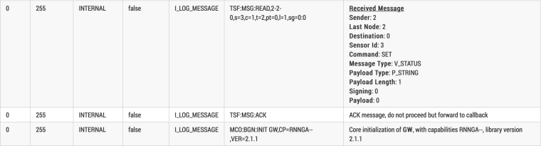
      1. Have you installed a capacitor between GND and VCC on your NRF? If so, what is the capacitance rating?
      2. Which version of the Arduino IDE are you using?
      posted in Troubleshooting
      blacey
      blacey
    • RE: Setup Livolo branded RF433 switches with Arduino

      @Anderson-Chan https://forum.mysensors.org/topic/5719/livolo-eu-switch-mysensors-integration

      posted in Development
      blacey
      blacey
    • RE: Ethernet gateway shows up on vera , but doens't want to include devices

      @hoggin I suggest that you step through the trouble-shooting steps below (in order):

      1. Ensure the Vera can see your gateway over USB, the most basic part of the connection - https://forum.mysensors.org/topic/5289/ui5-to-ui7-update/4
      2. Ensure that the right plugin files are installed on your vera - https://forum.mysensors.org/topic/5289/ui5-to-ui7-update/12
      3. If #1 and #2 checkout, then try the Serial Port troubleshooting section here - https://www.mysensors.org/controller/vera#configuring-the-vera-plugin-for-the-serialusb-gateway
      posted in Troubleshooting
      blacey
      blacey
    • RE: Ethernet gateway shows up on vera , but doens't want to include devices

      @hoggin Do you have the following in your gateway sketch?

      // Enable inclusion mode if your HA Controller supports it (e.g. Vera Controller)
      #define MY_INCLUSION_MODE_FEATURE
      // Enable Inclusion mode button on gateway
      #define MY_INCLUSION_BUTTON_FEATURE
      
      posted in Troubleshooting
      blacey
      blacey
    • RE: πŸ’¬ Sensebender Micro

      @marceltrapman The author updated his repo within the past few days so you could open an issue on his GitHub repo to see if he can help...

      posted in OpenHardware.io
      blacey
      blacey
    • RE: πŸ’¬ Sensebender Micro

      @tbowmo said in πŸ’¬ Sensebender Micro:

      @marceltrapman

      There is no kicad project available for the Sensebender Micro, I tried to convert it myself, but didn't succeed with it either.

      I haven't tried this Eagle->KiCAD convertor myself but it might do the trick or at least reduce a lot of the manual labor to convert...

      There's even a tutorial video.

      posted in OpenHardware.io
      blacey
      blacey
    • RE: US decora style wall switch

      @dbemowsk said in US decora style wall switch:

      @blacey Thanks for the tip. Just installed it on my Fedora 23 box.

      Excellent! Also, there is a pretty vibrant community behind FreeCAD so feel free to introduce yourself and ask questions on the FreeCAD forums - everyone is very helpful.

      posted in My Project
      blacey
      blacey
    • RE: πŸ’¬ Sensebender Gateway

      @tmn103 said in πŸ’¬ Sensebender Gateway:

      Just tried the MQTT gateway sketch and got some strange behaviour.

      Seems to pick up one of the nodes, but can't get an ip address or mqtt connection.

      Any ideas on what to try?

      IP: 255.255.255.255
      0;255;3;0;9;Attempting MQTT connection...
      IP: 0.0.0.0
      

      I would triple-check the IP addresses that you are using...

      posted in OpenHardware.io
      blacey
      blacey
    • RE: US decora style wall switch

      @dbemowsk Linux is the primary platform used by the FreeCAD devs so Linux is very well-supported.

      There is a PPA for stable and a PPA for daily developer builds.

      For example, to install the latest stable:

      sudo add-apt-repository ppa:freecad-maintainers/freecad-stable 
      sudo apt-get update
      sudo apt-get upgrade
      sudo apt-get install freecad freecad-doc 
      

      More details here - https://www.freecadweb.org/wiki/Install_on_Unix

      posted in My Project
      blacey
      blacey
    • RE: US decora style wall switch

      @dbemowsk said in US decora style wall switch:

      I think this 3D printer is going to help a lot with my HA hobby. Now I will be able to make custom enclosures and things and not have to search the web to say, "ehh, that will kinda fit". I just have to get used to using OpenSCAD.

      You should give FreeCAD a shot. Open source and runs on Windows, macOS and Windows and you can download the releases from GitHub

      posted in My Project
      blacey
      blacey
    • RE: Plugin not working..... error: unexpected symbol near '<' <0x2ba1d680>

      @otolosa I looks like the Vera plugin files are not installed correctly... I suggest that you remove the existing plugin files and reinstall following the instructions here - https://www.mysensors.org/controller/vera Make sure that you install the correct version - either UI5 or UI7.

      posted in Vera
      blacey
      blacey
    • RE: Problem Connecting to gateway

      @Jaime-Machado said in Problem Connecting to gateway:

      Can anyone tell me whats wrong here?

      Welcome to MySensors! Sounds like you are making great strides already. Usually the gateway is connected to an HA controller that is responsible for vending IDs to nodes during the inclusion/pairing process. In your case, if you are using a stand-alone gateway and node, then you will need to statically define the node id in the node sketch. The node id needs to be unique to each node and ranges from 1 to 254 (note, you can also have up to 254 child sensors per node).

      Try setting the following in the top of your node sketch before the MySensors.h include.

      #define MY_NODE_ID 1
      
      #include <MySensors.h>
      

      Whenever I need to statically set a node id, I usually do so at the very top of the sketch so it is clear when you open the sketch that the node id is statically defined.

      Finally, did you know that you can post code blocks using ``` before and after the code to make it more legible? That is what I used above.

      posted in Troubleshooting
      blacey
      blacey
    • RE: Using debounce twice in the same sketch

      @breimann It is usually helpful if you post the entire sketch within code blocks. You can create a code block by entering ``` before and after the code.

      posted in Development
      blacey
      blacey
    • RE: πŸ’¬ Building a Raspberry Pi Gateway

      @macvictor It would be great if you would submit this as a GitHub Pull Request. If you aren't comfortable with that, then I would encourage you to at least open a MySensors issue to add these RPI configuration options.

      posted in Announcements
      blacey
      blacey
    • RE: [SOLVED] Raspberry Pi Gateway to Vera UI7 Not adding sensors

      @anvil - great code sleuthing! I have been absent due to travel but to ensure this doesn't slip through the cracks and create future confusion for other users, I have filed GitHub issue https://github.com/mysensors/MySensors/issues/770 to add these defaults into the RPI gateway example for the 2.2.0 release.

      With your increased familiarity with the code base, feel free to make the change and submit a GitHub PR if you are so inclined, otherwise it will wait until one of the core members makes the change.

      posted in Troubleshooting
      blacey
      blacey
    • RE: Issue after updating from 1.5 to 2.1.1

      @tarends120

      @tekka optimized the NRF driver significantly between release 1.5.1 and 2.1.1 allowing the driver to push the radio a bit harder resulting in higher current-draw spikes. I experienced the same issue with nodes that had been running for several years but failing miserably after simply upgrading to the newer library. What I had to do was ensure that I had an adequate current supply for the radio to cope with the larger current-draw spikes. This included adding a 47uf capacitor across the NRF VCC and GND pin (actually @tekka recommended 100uf) and in one case swapping out a 3.3v LDO for a higher current LDO. So I would suggest that you first eliminate NRF power/current supply issues first. Additional background about NRF power needs are available here - https://arduino-info.wikispaces.com/Nrf24L01-2.4GHz-HowTo#PP

      By the way, the new MySensors Gateway that @tbowmo developed has no problem driving an NRF24L01+ PL/NA+ radio at high power.

      posted in Troubleshooting
      blacey
      blacey
    • RE: [SOLVED] Raspberry Pi Gateway to Vera UI7 Not adding sensors

      @pete1450 said:

      I've got nowhere. Unless someone happens to pop up with somewhere to look I guess I'll be going back to see if the serial gateway will work. As the problems exists after valid data already comes through I'd think the problem will still exist but who knows.

      First, sorry that no one has chimed in yet but let's see if we can make some progress here before you give up.

      1. Did the identical Vera configuration (UI7 and installed-plugin) work with a Serial gateway?
      2. It would be good if you can follow the steps in this post to confirm the correct Vera plugin is installed (i.e. compare the md5 checksums and if they differ, install the plugin using the link in the thread). https://forum.mysensors.org/topic/5289/ui5-to-ui7-update/13

      Cheers,
      Bruce

      posted in Troubleshooting
      blacey
      blacey
    • RE: IR Blaster (progress)

      @emc2 That pretty much sums up the above sans ESP8266 vs. Atmel 328p... My next iteration, albeit delayed, uses an SMD footprint compatible with both NRF and RFM. I had originally included an Si7021 temperature and humidity sensor but that isn't really necessary. @sparkman had requested a barrel connector to drive external IR LEDs.

      posted in Hardware
      blacey
      blacey
    • RE: Brand new Vera controller

      @dbemowsk You might want to try some of the steps detailed in this thread https://forum.mysensors.org/topic/5289/ui5-to-ui7-update/14 to confirm that you have the right versions of the plugin files installed.

      posted in Vera
      blacey
      blacey
    • RE: πŸ’¬ Button size radionode with sensors swarm extension

      Well done! πŸ‘ πŸ™‚

      posted in OpenHardware.io
      blacey
      blacey
    • RE: Pffff lib 2.0 ethernet module not working

      @riochicken I'm not sure these issues are the root cause for your problem, but a couple Ethernet issues have been resolved since the release 2.0 in July. You may want to try the development version to see if you have better luck.

      posted in Vera
      blacey
      blacey
    • RE: Battery status in scetch?

      @miro Hmmm, don't know - it is a Fibraro choice or controller ui choice, and I suspect the later. For example, on the Vera home controller, the Fibraro LED dimmers report power consumption on the parent node, not the RGBW children.

      posted in Development
      blacey
      blacey
    • RE: πŸ’¬ Wall Switch Insertable Node

      Interesting board. While you have designed this to be a wall-insertable board, one could envision packaging this into a small case with 4 buttons attached to the surface for a portable scene controller/remote. Well done!

      posted in OpenHardware.io
      blacey
      blacey
    • RE: Battery status in scetch?

      @miro said:

      Why is the battery status symbol showed on the node and not the sensor?

      Because there is a single power source for a given node even though a node can host multiple sensors. Many home automation controllers expect and present the battery status for a given node because it is a property of the node and not the sensors. Does this make sense?

      posted in Development
      blacey
      blacey
    • RE: Reversed Relay

      @Rooster If you only want to send the initial values once, you can move the logic to setup(). Setup is called after the radio transport is initialized however you may need the 2.1 beta.

      posted in Home Assistant
      blacey
      blacey
    • RE: problem about gas sensor

      @Reza said:

      /Hardware Related Macros************/
      #define MQ_SENSOR_ANALOG_PIN (0) //define which analog input channel you are going to use

      If I were to hazard a guess, it looks like you did not set MQ_SENSOR_ANALOG_PIN to the pin # to which the MQ_SENSOR is attached. Pin 0 is not valid.

      posted in Troubleshooting
      blacey
      blacey
    • RE: UI5 to UI7 update

      @GRB Super! Let us know if the final verification with an actual sensor works and feel free to ask questions if it doesn't.

      posted in Vera
      blacey
      blacey
    • RE: IR Sensor How to Use Manual codes

      @Matt-Pitts Looks like you are making good progress but I am surprised that volume up and down are the same - perhaps you need to confirm by recording them again.

      Effectively, you will want to create a sketch that sends an IR value based upon the message received. There is some prior art in this forum post that sends and on/off code in response to V_LIGHT messages being received. You can start by using that sketch to simply turn your AMP on and off by replacing the codes sent in the sketch. Once you have that working, then you can extend the sketch to support the additional codes by adding 2 child devices for source and volume control.

      Does this help?

      posted in Troubleshooting
      blacey
      blacey
    • RE: IR Sensor How to Use Manual codes

      @Matt-Pitts It might be easier to add an IR receiver (temporarily) to your IR node and record the IR values using your NAD Amp remote. With a little googling, you might be able to find resources that translate the downloadable codes (often Pronto format) to the IR code format used by IRLib on Arduino.

      posted in Troubleshooting
      blacey
      blacey
    • RE: W5100 MQTT gateway fails to connect to broker

      @Matt-Pitts Excellent! πŸ‘

      posted in Troubleshooting
      blacey
      blacey
    • RE: UI5 to UI7 update

      @GRB Ok, let's try to replace the existing plugin files by doing the following.

      1. ssh into your vera and remove the existing plugin by typing the following command

      rm /etc/cmh-ludl/*_Arduino*

      1. On your PC, download a .zip of the UI7 only branch from https://api.github.com/repos/mysensors/Vera/zipball/UI7 This will ensure that you are pulling the latest UI7 branch from GitHub (avoid git nuances). The downloaded file should be named mysensors-Vera-73ed9b7.zip. Unzip mysensors-Vera-73ed9b7.zip unless your browser unzips automatically.

      2. ssh into your vera and log the plugin output by entering the following command:

      tail -f /var/log/cmh/LuaUPnP.log | grep Arduino
      

      This will log the output for the next step.

      1. Using the Vera UI (Apps->Develop Apps->Luup files), upload the following plugin files to your Vera from the mysensors-Vera-73ed9b7 directory (be sure "Restart Luup after reload" is checked).
      D_Arduino1.json
      D_Arduino1.xml
      D_ArduinoNode1.json
      D_ArduinoNode1.xml
      D_ArduinoRelay1.json
      D_ArduinoRelay1.xml
      I_Arduino1.xml
      L_Arduino.lua
      S_Arduino.xml
      S_ArduinoNode.xml
      
      1. Confirm the install versions by entering the following command:
      sha1sum /etc/cmh-ludl/*_Arduino*
      

      Please post the results.

      1. On your vera, confirm that the plugin initialized properly by looking at the log results from step 3. Please post the log results here.

      Hopefully, the root cause is just a botched plugin install... This should rule it out.

      posted in Vera
      blacey
      blacey
    • RE: Hello, Can you help me? LDR Sensor

      @Nathan-Matos Clearly you are a quick study and have made great progress in a short time. Let us know if you need anything else.

      posted in Development
      blacey
      blacey
    • RE: W5100 MQTT gateway fails to connect to broker

      @Matt-Pitts It would be helpful if you post your sketch... and possibly your mosquitto broker config file. .

      posted in Troubleshooting
      blacey
      blacey
    • RE: Powering mote 24/7 using only a supercap and solar

      @NeverDie said:

      Not that it proves anything, but using KiCAD to look at the BQstripped PCB, I notice that the PCB designer chose to connect pins 12 and 13 both directly to each other and directly to the thermal pad.

      Did you say KiCAD? πŸ‘ πŸ‘ πŸ‘

      posted in My Project
      blacey
      blacey
    • RE: Hello, Can you help me? LDR Sensor

      @Nathan-Matos Yes, I got the joke and appreciate the humor πŸ˜‰

      That said, if you are monitoring the node over serial, you will want to do the same thing with the gateway but be sure to enable MY_DEBUG so it logs the messages to the Arduino serial console.

      This line in lightLevel sketch is where the value is sent to the gateway. Assuming you have the node speaking to the gateway using either NRF or RFM radios, then you should see the messages appearing in the serial console. Normally a home automation controller plugin would connect to the gateway and use the Serial API but in this setup, you will be a human controller so you will need to interpret the Serial API yourself to verify the behavior.

      You will want to power up your gateway first and then power up your node(s) at which point you should see the node send the sketch version to the gateway followed by presenting its LDR child sensor to the gateway. You should see these interactions in the serial console of the gateway. Finally, whenever the light level changes and the node sends the new level to the gateway, you should see that too.

      Finally, are you using Windows or a Mac? If Windows and/or you are familiar with Wine, I recommend that you consider using @tekka's awesome MYSController that he developed for debugging MySensors networks. The way to think about it for your purposes, is that it will run on your PC and connect to your gateway over the serial connection and present the Serial API information to you in a much more human consumable form... You can find additional info in this forum post.

      So, to reiterate, once you have a single node talking to a single gateway connected to your PC, then you should introduce MYSController and at that point, start working on a second node and implementing the node-to-node communication.

      Thanks for the update and great progress so far!

      posted in Development
      blacey
      blacey
    • RE: Invert the relay in the sketch

      @derksuh Sorry to hear but your sketch looks good. Are you using the MySensors development branch? If not, doing so will probably fix the behavior because there was a bug in the 2.0 release that prevented messages from being sent (i.e. the request()) in the setup() method of a sketch.

      Once you upgrade to the MySensors development branch, if it still doesn't behave properly, please post the messages logged by the node, with #MY_DEBUG enabled.

      posted in Development
      blacey
      blacey
    • RE: Newbie Code Question: How is motion sensor tigger controlling code flow?

      @Sensor you could also checkout @mfalkvidd's dimmable LED kitchen light project for autonomous dimming using a local gesture or proximity sensor.

      posted in Development
      blacey
      blacey
    • RE: Hello, Can you help me? LDR Sensor

      @Nathan-Matos said:

      Perhaps you know the Mysensors.h set of instructions and maybe and example of the program

      Did you see all the examples packaged with MySensors? A great place to start - https://github.com/mysensors/MySensors/tree/development/examples.

      For the serial gateway, the sketch couldn't be simpler - https://github.com/mysensors/MySensors/blob/development/examples/GatewaySerial/GatewaySerial.ino

      For the LDR sensor, you can probably adapt one of the existing example sensor sketches for your needs - for example, the existing light sensor example https://github.com/mysensors/MySensors/blob/development/examples/LightSensor/LightSensor.ino

      Oh, and don't forget the build section - here are all the details for building 1 of two different light level sensors - https://www.mysensors.org/build/light-bh1750

      Does this help?

      posted in Development
      blacey
      blacey
    • RE: UI5 to UI7 update

      @GRB I am sorry you are still struggling with this but I am fairly certain we will figure it out. Thanks for posting your logs they are and will be helpful. It seems the plugin loads, purportedly connects to the serial port, requests the library version from the gateway but times out during lua_startup even though the gateway sends back version 1.4.1... I know we covered this before I think at this point, we should definitely verify the plugin files installed on your Vera match mine by computing a shasum over them. Please ssh to your vera and run sha1sum /etc/cmh-ludl/*_Arduino* and post the results here. If the checksums don't match, then we will know what to do. If they do match, then we will have definitively ruled out the plugin install and will have to dig further.

      sha1sum /etc/cmh-ludl/*_Arduino*
      f9875310ea581c6384046dfd733dc5c9e436ef20  /etc/cmh-ludl/D_Arduino1.json.lzo
      e3c4493c7dff216c152b8a4d50c169acf636b1fc  /etc/cmh-ludl/D_Arduino1.xml.lzo
      8f0186c85c9a6ef6e0e8ba0755f88cbb5d326e30  /etc/cmh-ludl/D_ArduinoNode1.json.lzo
      7d66187bb75beb01606f607ad1e82a6fa6b2a552  /etc/cmh-ludl/D_ArduinoNode1.xml.lzo
      722b702937db7aedcb03346229fcc38363b2c378  /etc/cmh-ludl/D_ArduinoRelay1.json.lzo
      05ea89a8d904f436c60bd326315724e79c5c47de  /etc/cmh-ludl/D_ArduinoRelay1.xml.lzo
      ed15bfde68e6615b7615bd6230ca8040a50f5f28  /etc/cmh-ludl/I_Arduino1.xml.lzo
      2f0603b6192006f88e3582788a13a168391ceee4  /etc/cmh-ludl/L_Arduino.lua.lzo
      dc1e8a26833890f2d1f412c9b2e915724576cbd4  /etc/cmh-ludl/S_Arduino.xml.lzo
      64f886de376e2d932cd55bdf8a6367ed7a394d55  /etc/cmh-ludl/S_ArduinoNode.xml.lzo
      
      posted in Vera
      blacey
      blacey
    • RE: Hello, Can you help me? LDR Sensor

      @Nathan-Matos Welcome to MySensors - nice to have you on board. Your project sounds interesting and is a great match for MySensors. I would start by reading the getting started section and from there plan to build a serial gateway that connects to your PC and one LDR sensor first (no need to complicate it with two just yet). Given you know a bit about Arduino programming, this should be that hard. To keep things simple, you can ignore anything to do with Controllers because you PC will be effectively that through the Arduino IDE and plan to use static node addresses (for example, gateway is 0, node one is 1, node 2 is two).

      Once you have the gateway and a single LDR sensor working, I would add a second LDR sensor that also communicates with the gateway. Once you have one gateway and two independent sensors, you can modify your sensor node sketches so each node sends messages directly to the other by using creating a MyMessage to send and then calling setDestination() on it to set the peer node that you would like to send to.

      Good luck and look forward to hearing about your progress along the way.

      posted in Development
      blacey
      blacey
    • RE: Invert the relay in the sketch

      @derksuh Exactly - good job! So, is it working as expected? For example, if you turn the relay on and then reboot the node, does the node come up, ask for the relay status, receive relay on and then try to turn the relay on? You should be able to see this in the messaging sequence on the node.

      posted in Development
      blacey
      blacey
    • RE: Looking to buy a vera controller

      @dbemowsk Personally, I would recommend the Plus. It is the fastest, has the latest z-wave plus chip and supports bluetooth and zigbee. It also has the most RAM which is good for handling a large number of devices. I wouldn't drop down below the Edge and going with the Edge means a slower controller, no bluetooth or zigbee and less RAM for devices/plugins. I have deployed vera 3s, vera edges and the 3 Vera Plus' - the Plus is by far their best and I really recommend it.

      posted in General Discussion
      blacey
      blacey
    • RE: Invert the relay in the sketch

      @derksuh said:

      I did not get it working the way i would like. I now used a different sketch.
      here i had the same problem but i just set the relay_OFF from 0 to 1, and the Relay_ON from 1 to 0
      And with this sketch it worked fine.

      Your new sketch looks much better, glad you figured it out! πŸ‘ You might want to remove the saveState() from your receive() method because the "saved -state" is not being used and this will prevent unnecessary writes to EEPROM which has a limited lifespan. Also, you might want to request the relay status from the gateway in setup() so the node will set the relay status to that of they gateway (i.e. the response to a request() sent in setup() will be handled by your existing receive() method).

      posted in Development
      blacey
      blacey
    • RE: Invert the relay in the sketch

      As I said in my last post, you can put it in the receive() method of your node sketch. Basically, this will invert the relay state sent to PiMac only...

      void receive(const MyMessage &message) {
         Serial.println("Received message...");
       
         if (message.type == V_STATUS) {
           // Change relay state
           state = message.getByte();
           digitalWrite(RELAY_PIN, state);
           send( msgRlay.set(state == 0 ? 1 : 0) );
         }
      }
      
      posted in Development
      blacey
      blacey
    • RE: ESp arduino + domoticz + read light switch status (on / off)

      @marcin.kasinski Hmmm, now I'm confused. Are you using ESP for your Gateway or Node or both? Do I understand correctly that you have not attached either an NRF24 or RFM69 radio to your node (all #defines for radio are commented out)? The MySensors gateway and nodes only communicate with each over NRF24 or RFM69 radios (i.e. not WiFi).

      posted in Development
      blacey
      blacey
    • RE: IR Blaster (progress)

      @korttoma Apologies to you and others; I wouldn't say that I have abandoned this project but it is fair to say that I haven't had the time to devote to this either so it is woefully stalled. @scalz is working on something similar that may fit but bill nicely after which I will decide whether this warrants further development or not.

      posted in Hardware
      blacey
      blacey
    • RE: Invert the relay in the sketch

      @derksuh Is the relay working the way you want it to and you just want to invert the display in PiMatic? If so, you can do the following in the receive() method:

          send( msgRlay.set(state == 0 ? 1 : 0) );
      
      posted in Development
      blacey
      blacey
    • RE: Invert the relay in the sketch

      @derksuh Ok, I took a shot at refactoring your sketch. I didn't have much time and I only ensured that it compiles so your MMV... This could probably be simplified even more but you know the old saying, "If I had more time, I would write less code" πŸ˜‰

      #define MY_DEBUG
      #define MY_RADIO_NRF24
      #define MY_REPEATER_FEATURE
      #define MY_NODE_ID 1
       
      #include <SPI.h>
      #include <MySensors.h>
      #include <DHT.h>
      
      // Set this to the pin you connected the DHT's data pin to
      #define DHT_DATA_PIN 6
      
      // Set this offset if the sensor has a permanent small offset to the real temperatures
      #define SENSOR_TEMP_OFFSET 0
      
      // Sleep time between sensor updates (in milliseconds)
      // Must be >1000ms for DHT22 and >2000ms for DHT11
      static const uint64_t UPDATE_INTERVAL = 60000;
      
      // Force sending an update of the temperature after n sensor reads, so a controller showing the
      // timestamp of the last update doesn't show something like 3 hours in the unlikely case, that
      // the value didn't change since;
      // i.e. the sensor would force sending an update every UPDATE_INTERVAL*FORCE_UPDATE_N_READS [ms]
      static const uint8_t FORCE_UPDATE_N_READS = 10;
      
      #define CHILD_ID_HUM 0
      #define CHILD_ID_TEMP 1
      #define CHILD_ID_RLAY 2
      
      #define RELAY_PIN  3
      #define RELAY_ON 1  
      #define RELAY_OFF 0
      
      #define TEMP 0
      #define HUMI 1
      
      byte state = 0;
      bool metric = true;
      
      MyMessage msgHum(CHILD_ID_HUM, V_HUM);
      MyMessage msgTemp(CHILD_ID_TEMP, V_TEMP);
      MyMessage msgRlay(CHILD_ID_RLAY, V_STATUS);
      
      typedef struct {
        float last;
        uint8_t nNoUpdates;
      } sensorState_t;
      
      sensorState_t dhtState[2];
      
      DHT dht;
      
      void presentation()   
      { 
        // Send the sketch version information to the gateway
        sendSketchInfo("TempHumidRelay", "1.1");
        
        // Register all sensors to gw (they will be created as child devices)
        present(CHILD_ID_HUM, S_HUM);
        present(CHILD_ID_TEMP, S_TEMP);
        present(CHILD_ID_RLAY, S_BINARY);
      
        // Ask the gateway for the units of measure to use
        metric = getConfig().isMetric;
      }
      
      void setup()
      {
        // Make sure relays are off when starting up
        pinMode(RELAY_PIN, OUTPUT);
        digitalWrite(RELAY_PIN, RELAY_OFF);
      
        // Initialize the Temperature & Humidity sensor, first reading will be sent from loop()
        if (UPDATE_INTERVAL >= dht.getMinimumSamplingPeriod()) {
          dht.setup(DHT_DATA_PIN); // set data pin of DHT sensor and model (e.g. DHT_22, DHT_11)
        } else {
          Serial.println("Warning: UPDATE_INTERVAL is smaller than supported by the sensor!");
          Serial.println("Increase UPDATE_INTERVAL and re-upload sketch...");
        }
       
        // Request the latest relay status from the gateway 
        Serial.println("Requesting initial value from controller");
        request(CHILD_ID_RLAY, V_STATUS);
      }
      
      void loop()      
      { 
        // Sleep until next valid interal to read temperature and humidity
        wait(UPDATE_INTERVAL);
      
        // Read current temperature & humidity from DHT22
        dht.readSensor(true);
        float temperature = dht.getTemperature();
      
        // Only send temperature if it has changed since the last measurement or if we didn't send an update for n times
        if (temperature != dhtState[TEMP].last || dhtState[TEMP].nNoUpdates >= FORCE_UPDATE_N_READS) {
          dhtState[TEMP].last = temperature;
          temperature = metric ? temperature : dht.toFahrenheit(temperature);
          temperature += SENSOR_TEMP_OFFSET;
          send(msgTemp.set(temperature, 1));
          #ifdef MY_DEBUG
            Serial.print("T: ");
            Serial.println(temperature);
          #endif
          dhtState[TEMP].nNoUpdates = 0;
        }
        else if (isnan(temperature)) {
          Serial.println("Failed reading temperature from DHT!");
        } else {
          // Increase no update counter if the temperature stayed the same
          dhtState[TEMP].nNoUpdates++;
        }
      
        // Retrieve the current humidity
        float humidity = dht.getHumidity();
      
        // Only send humidity if it changed since the last measurement or if we didn't send an update for n times
        if (humidity != dhtState[HUMI].last || dhtState[HUMI].nNoUpdates >= FORCE_UPDATE_N_READS) {
          dhtState[HUMI].last = humidity;
          send(msgHum.set(humidity, 1));
          
          #ifdef MY_DEBUG
            Serial.print("H: ");
            Serial.println(humidity);
          #endif
          dhtState[HUMI].nNoUpdates = 0;
      
        } else if (isnan(humidity)) {
          Serial.println("Failed reading humidity from DHT");
        } else {
          // Increase no update counter if the humidity stayed the same
          dhtState[HUMI].nNoUpdates++;
        }
      }
      
      void receive(const MyMessage &message) {
        Serial.println("Received message...");
      
        if (message.type == V_STATUS) {
          // Change relay state
          state = message.getByte();
          digitalWrite(RELAY_PIN, state);
          send(msgRlay.set(state));
        }
      }
      
      posted in Development
      blacey
      blacey
    • RE: Invert the relay in the sketch

      @derksuh I see a couple of potential problems:

      1. In setup(), you are attempt to turn the relay off before setting the pin mode. You need to reverse the following two lines.
        // Make sure relays are off when starting up
        digitalWrite(RELAY_PIN, RELAY_OFF);
        pinMode(RELAY_PIN, OUTPUT);
      
      1. What are you debouncing()? You never attach debouncer to a pin to read (e.g. debouncer.attach())?

      2. I actually see a number of other issues but it would be better to understand your use case/requirements. Can you describe what you want to happen when you first power up the node and, while the node is in steady state, and any interactions/control with the relay on the node. For example (hypothetical).

      Startup:
      1. Set relay status to last known gateway state (on/off)
      2. Send current temperature and humidity to gateway

      Steady state:
      1. Send temperature and humidity to gateway ever xx seconds/minutes
      2. Allow gateway to turn fan on/off (e.g. scene to turn on fan when humidity is high, off when low, manual user control, etc.)

      I saw potential requirements conflicts hence my question regarding your view of the requirements/envisioned behavior.

      posted in Development
      blacey
      blacey
    • RE: ESp arduino + domoticz + read light switch status (on / off)

      @marcin.kasinski said:

      I placed
      request(3, V_STATUS);

      in setup () and loop()

      This code does nothing.

      No log messages in domoticz.
      No debug messages on esp side.

      Did you upgrade to the development version of MySensors?

      Also, please post your entire sketch...

      Another thing:
      After ESP restarts it isn't visible in domoticz automically.

      We will have to figure this problem out first. Maybe the sketch will include a hint.

      posted in Development
      blacey
      blacey
    • RE: ESp arduino + domoticz + read light switch status (on / off)

      @marcin.kasinski All you need to do is ask the gateway for the light status in your setup() method. The gateway will respond to request() by sending a V_STATUS message for your light to your ESP node.

      NOTE: Currently there is a bug in the MYS 2.0 release that invokes the sketch setup() before presentation() and you can't send messages to the gateway until presentation() completes. You will need to upgrade to the development branch (next beta) in order for this to work (i.e. ensure that setup() is call after presentation().

      void setup()  
      {
        //Synchronize relay state with gateway - this will result in receive() being called.
        request( CHILD_ID, V_STATUS );
      }
      
      posted in Development
      blacey
      blacey
    • RE: Powering mote 24/7 using only a supercap and solar

      @NeverDie said:

      I guess my purchase of the PCB's from Osh Park was a waste, because I don't see how I could solder discrete parts which are that tiny. Any ideas?

      Reflow oven - http://makezine.com/2015/04/15/diy-open-source-reflow-oven/ As an aside, I just had lunch with Peter Easton last week, the inventor of ControlLeo, and he owns the DIY reflow oven market so you can't go wrong. Of course, I built one a couple years ago πŸ‘

      posted in My Project
      blacey
      blacey
    • RE: request() not working with HomeAssistant

      @ajlisy Here are a couple of ideas:

      1. Do you ever see Got a message in your log? If not, what if you turn on acks in the send()? If you are receiving messages, you might want to add logging of the message.type.

      2. wait() will return true if it receives the message and command specified in the arguments and false if it doesn't (timer expired) so you could change your wait(2000, C_SET,V_STATUS); to the following to see what is happening at this point in the sketch:

      bool resp = wait( 2000, C_SET,V_STATUS );
      Serial.print( "wait( 2000, C_SET, V_STATUS ) return = " );
      Serial.println(resp ? "true" : "false");
      
      1. If wait() returns true above, then that confirms that the node is receiving a V_STATUS back from the gateway so the basic request response is functioning. If that is the case, then what happens if you change the wait(2000,C_SET,V_STATUS); in loop() to wait( 1000 );? Perhaps wait()'ing on a specific message consumes that message from the queue preventing the receive() callback from being called? It is not clear that the second wait() is even needed... I would think this simplified version would work:
      void loop()
      {
         send( msg.set( flip = flip ? 0 : 1 ), false );
         request( CHILD_ID, V_STATUS );
         wait( 1000 ); 
      }
      
      1. If you want to synchronize the node state with the Home Assistant controller, you can send the request message in setup() [NOTE: Requires development branch]
      void setup()  
      {
        // Make sure relays are off when starting up
        digitalWrite(RELAY_PIN, RELAY_OFF);
        // Then set relay pins in output mode
        pinMode(RELAY_PIN, OUTPUT);   
        //Synchronize relay state with gateway - this will result in receive() being called.
        request( CHILD_ID, V_STATUS );
      }
      
      posted in Home Assistant
      blacey
      blacey
    • RE: I can't get it to work (Nano V3.0, NRF24L01+Z)

      @mfalkvidd said:

      However, it looks like the header pins have not been soldered to the Nano.

      Good eyes and nice catch πŸ˜‰

      posted in Troubleshooting
      blacey
      blacey
    • RE: UI5 to UI7 update

      @GRB the command I suggested you use is lsusb -v -s 002:003, not lsusb -v -3 002:003?

      Looking forward to your results after the troubleshooting steps...

      posted in Vera
      blacey
      blacey
    • RE: UI5 to UI7 update

      @GRB No need to apologize - we are trying to get to the root cause. What happens if you use the command lsusb -v -s 002:003? I suspect that will show you the FTDI device details because it has the id 0403:6001. If that is the case, then I suggest that you try the troubleshooting directions posted here - https://www.mysensors.org/controller/vera To paraphrase, the steps are:

      1. Unplug the MySensors gateway from the Vera USB port
      2. Restart the Vera LUUP Engine (Settings->Z-Wave Settings->Reload Engine)
      3. Plug gateway into the Vera USB port
      4. Restart the Vera LUUP Engine (Settings->Z-Wave Settings->Reload Engine)
      5. Re-configure serial port as described above (typically, you only need to reset the baud rate to 115200)

      Now that you have ssh access to your Vera, it is also helpful to view the log entries using the command tail -f /var/log/cmh/LuaUPnP.log | grep Arduino on your Vera while performing the steps above. For example, when I reload the LUUP Engine on my Vera Plus running UI7, I see the following in my logs:

      50	11/17/16 21:57:07.212	luup_log:47: Arduino plugin: loading library L_Arduino ... <0x76ef7520>
      50	11/17/16 21:57:07.235	luup_log:47: Arduino plugin: library L_Arduino loaded <0x76ef7520>
      50	11/17/16 21:57:07.235	luup_log:47: Arduino: urn:upnp-arduino-cc:serviceId:arduino1,PluginVersion, 1.5, 47 <0x76ef7520>
      50	11/17/16 21:57:07.236	luup_log:47: Arduino: urn:upnp-arduino-cc:serviceId:arduino1,GWAddress, -, 47 <0x76ef7520>
      50	11/17/16 21:57:07.236	luup_log:47: Arduino: Trying for a serial connection <0x76ef7520>
      50	11/17/16 21:57:07.236	luup_log:47: Arduino: Serial port is connected <0x76ef7520>
      50	11/17/16 21:57:07.237	luup_log:47: Arduino: Baud is 115200 <0x76ef7520>
      50	11/17/16 21:57:07.237	luup_log:47: Arduino: urn:upnp-arduino-cc:serviceId:arduino1,GWAddress, 91(115200), 47 <0x76ef7520>
      50	11/17/16 21:57:07.239	luup_log:47: Arduino: Sending: 0;0;3;0;2;Get Version <0x76ef7520>
      

      What are you seeing?

      posted in Vera
      blacey
      blacey
    • RE: Help with hacking a wireless outdoor weather station

      You might want to checkout @Yveaux's impressive prior art - http://yveaux.blogspot.com/2015/08/hacking-wireless-weather-display.html

      posted in Hardware
      blacey
      blacey
    • RE: UI5 to UI7 update

      @GRB You will need to ssh into your vera using the password on the bottom of the unit. On macOS or Linux, you would ssh root@<vera ip address> without the < or >. On Windows you will need to use an ssh client such as PuTTY which is free. Enter the password on the bottom of the unit when prompted. Here is a Micasaverde Wiki article on connecting to your Vera.

      Once you have connected, in the shell, just enter the commands as I did. To list your usb devices, use lsusb. If you see an FTDI device (Future Technology Devices International), you can list the details by using lsusb -v -s <Bus>:<Device> without the < or >. For example, on mine, the FTDI devices is on Bus 001, Device 006 so I used lsusb -v -s 001:006.

      Give it a try and if you run into problems, post back here. It would be good to see the output of your devices.

      posted in Vera
      blacey
      blacey
    • RE: Powering mote 24/7 using only a supercap and solar

      @NeverDie And bootchk designed it using KiCAD - well done! As a side note, in the very early days of the MySensors core team (@hek, @tbowmo, @Anticimex and I) decided that, in the spirit of open source, to abandon commercial / proprietary CAD programs for the MySensors official board designs, hence why SenseBender Micro is in KiCAD and the forthcoming gateway will be too. We wanted to ensure that all board designs would be available to users freely for modification and improvements. While KiCAD is the standard for the official MySensors board designs, it would be nice to see broader adoption by the MySensors community as well (as I step down from my soapbox) πŸ˜‰

      posted in My Project
      blacey
      blacey
    • RE: Anyone tried the $199 Monoprice 3D printer?

      @NeverDie It all comes down to hot-end temperature range and a heated bed. Any printer that supports ABS (higher hot-end temperature and a heated bed), will support HIPS and nGen.

      posted in Enclosures / 3D Printing
      blacey
      blacey
    • RE: openHAB 2.0 binding

      @TimO Nice! While I have been a longtime Vera user, I think my next move will be OpenHab. I sponsored the Pine64 project on KickStarter and have one sitting on my project desk ready for some prototyping. I think it is great that you are making MySensors a first-class OpenHab 2.0 citizen. Hopefully Kai or one of the OpenHab contributors will merge your binding into the distro.

      posted in OpenHAB
      blacey
      blacey
    • RE: Anyone tried the $199 Monoprice 3D printer?

      @NeverDie ABS is the most popular filament but my current goto filament is HIPS. It has a lot of the same properties as ABS but without the smell and is a bit more forgiving. There is a promising new player on the market called nGen but I haven't used it yet.

      posted in Enclosures / 3D Printing
      blacey
      blacey
    • RE: UI5 to UI7 update

      @GRB

      1. Ok, are you using a genuine nano or a clone? I know others have reported issues with certain clones being recognized. Logging into my VeraPlus and listing the usb devices, I see the following:
      root@OpenWrt:~# lsusb 
      Bus 001 Device 002: ID 05e3:0610 Genesys Logic, Inc. 4-port hub
      Bus 001 Device 003: ID 0e8d:7662 MediaTek Inc. 
      Bus 001 Device 001: ID 1d6b:0002 Linux Foundation 2.0 root hub
      Bus 002 Device 001: ID 1d6b:0003 Linux Foundation 3.0 root hub
      Bus 001 Device 006: ID 0403:6001 Future Technology Devices International, Ltd FT232 USB-Serial (UART) IC
      Bus 001 Device 007: ID 0781:5571 SanDisk Corp. Cruzer Fit
      

      The nano shows up as an FTDI device - 006 on bus 001. Here are the details for the nano...

      root@OpenWrt:~# lsusb -v -s 001:006
      
      Bus 001 Device 006: ID 0403:6001 Future Technology Devices International, Ltd FT232 USB-Serial (UART) IC
      Device Descriptor:
        bLength                18
        bDescriptorType         1
        bcdUSB               2.00
        bDeviceClass            0 (Defined at Interface level)
        bDeviceSubClass         0 
        bDeviceProtocol         0 
        bMaxPacketSize0         8
        idVendor           0x0403 Future Technology Devices International, Ltd
        idProduct          0x6001 FT232 USB-Serial (UART) IC
        bcdDevice            6.00
        iManufacturer           1 FTDI
        iProduct                2 FT232R USB UART
        iSerial                 3 A7036KQ4
        bNumConfigurations      1
        Configuration Descriptor:
          bLength                 9
          bDescriptorType         2
          wTotalLength           32
          bNumInterfaces          1
          bConfigurationValue     1
          iConfiguration          0 
          bmAttributes         0xa0
            (Bus Powered)
            Remote Wakeup
          MaxPower               90mA
          Interface Descriptor:
            bLength                 9
            bDescriptorType         4
            bInterfaceNumber        0
            bAlternateSetting       0
            bNumEndpoints           2
            bInterfaceClass       255 Vendor Specific Class
            bInterfaceSubClass    255 Vendor Specific Subclass
            bInterfaceProtocol    255 Vendor Specific Protocol
            iInterface              2 FT232R USB UART
            Endpoint Descriptor:
              bLength                 7
              bDescriptorType         5
              bEndpointAddress     0x81  EP 1 IN
              bmAttributes            2
                Transfer Type            Bulk
                Synch Type               None
                Usage Type               Data
              wMaxPacketSize     0x0040  1x 64 bytes
              bInterval               0
            Endpoint Descriptor:
              bLength                 7
              bDescriptorType         5
              bEndpointAddress     0x02  EP 2 OUT
              bmAttributes            2
                Transfer Type            Bulk
                Synch Type               None
                Usage Type               Data
              wMaxPacketSize     0x0040  1x 64 bytes
              bInterval               0
      Device Status:     0x0000
        (Bus Powered)
      

      What do you see when you log into your Vera and list the USB devices?

      1. If the nano is visible on the usb bus as described above, perhaps you should try a powered USB hub to ensure that ample power is delivered to the nano.
      posted in Vera
      blacey
      blacey