Navigation

    • Register
    • Login
    • OpenHardware.io
    • Categories
    • Recent
    • Tags
    • Popular
    1. Home
    2. evb
    3. Best
    • Profile
    • Following
    • Followers
    • Topics
    • Posts
    • Best
    • Groups

    Best posts made by evb

    • Checking mechanical locked doors by a battery-based windows/door sensor node

      The trigger to start this project was remarking, for the umpteenth time in the morning, that the door had been unlocked again all night.
      Replacing the mechanical locks on the 4 doors by electric locks was out of the question, too expensive and the need for electric cables that were not present.

      So, how to detect if a mechanical lock is closed?

      The internet is an incredible source of ideas:
      https://community.home-assistant.io/t/how-i-made-my-dumb-locks-a-little-smarter/55174
      https://community.home-assistant.io/t/i-made-a-simple-lock-sensor-with-xiaomi-door-sensor-some-battery-holders-and-a-soldering-iron/49445
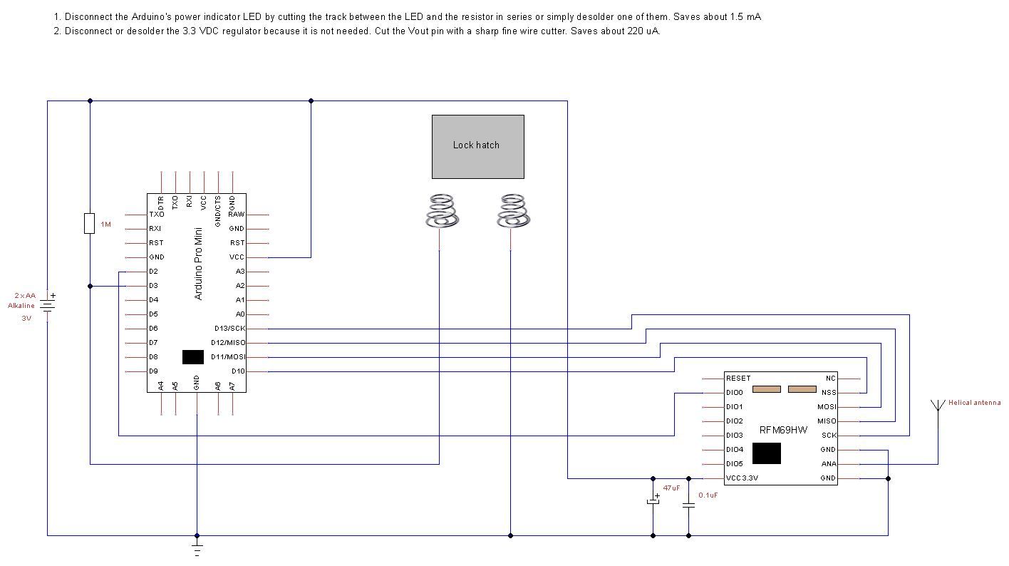
      With this idea, let the bolt close a contact, I could use the standard window/door sensor node!
      So I made my version by using springs I found in my junk bin mounted on a piece of wood, namely the wooden stick of an ice cream 😊
      My first prototype was working, but not really a piece of art ☹

      20201104_172524.jpg
      Remember to always drill holes because the wood of the stick splits very easily.

      I did use battery springs for my other nodes, they are stronger and easier to use.

      The battery-based windows/door sensor node : hardware

      I had never built a battery based node before, so as a first step, I did read the site article on the MySensors site: https://www.mysensors.org/build/battery

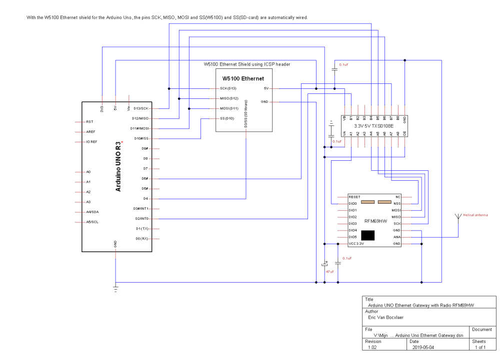
      Luckily, I already had Pro Mini's and enough RFM69HW radios in stock.
      Today I know that I did probably the wrong choice by using the Pro Mini’s. They are good in low consumption, but a bare bone 328P used like in this topic https://forum.mysensors.org/topic/2067/my-slim-2aa-battery-node is still better...
      But we will see how far these Pro Mini’s will take us on 2x AA batteries!

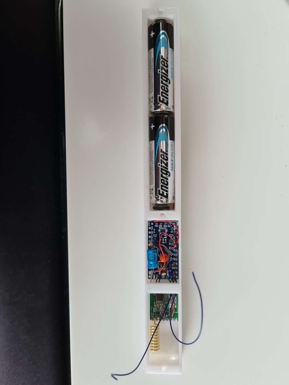
      My first node was based on the idea to use the same enclosure as in the above topic. In Belgium these cable ducts are known under the name Legrand and I had a still a piece of more then 1 meter lying around, a surplus from the renovations.

      20201109_114415.jpg
      20201104_122033.jpg
      20201104_172513.jpg
      Because I used a Pro Mini and not a bare bone 328P, I was obliged to use 2 covers of the cable duct instead of a cover and base. The base of the cable duct was not broad enough for the Pro Mini.

      With the hardware tricks of the MySensor battery node site article on the Pro Mini, I could obtain a current consumption of 133Β΅A in deep sleep (Modified Pro Mini, RFM69HW and the open contact).

      To minimize the current with a closed contact, I did not use the internal pull-up resistor of the 329P (internal pullup resistor value around 30KOhm), but an external 1M ohm resistor. With closed contact and deep sleep, I have now around 136Β΅A.

      Arduino Pro Mini Lock Battery Sensor.jpg

      The battery-based windows/door sensor node : software
      Besides the hardware modifications done at the Pro Mini, you can also do software modifications to save power consumption.
      In the same topic https://forum.mysensors.org/topic/2067/my-slim-2aa-battery-node, the author @m26872 mentioned the use of a new bootloader with a 1MHz internal clock and a BOD (cpu brown out) disabled.

      Today (2020-12-28) we can use the github project MiniCore https://github.com/MCUdude/MiniCore to program our Arduino Pro Mini with the new bootloader. See the readme of the project MiniCore on Github. It explains everything: the theory, the installation and the Getting Started.

      After installing MiniCore, I used following configuration:

      • board : ATmega328
      • clock : internal 1 MHz
      • BOD : BOD 1.8V
      • EEPROM : EEPROM retained
      • Variant : 328P / 328PA
      • Bootloader : Yes (UART0)

      Remark 1
      I did not disable completely the BOD. Why? I did read on forums that the processor could write garbage into the memory when below 1.8V, so for safety’s sake, I did set it to 1.8V.
      Remark 2
      There are reports that using the Arduino Pro Mini at internal 1Mhz gives sometimes problems with the MySensors library. It was not clear to me if it was with the 1.x version of MySensors or the 2.x version, so I did take my chance and used 1MHz with the 2.3 version of MySensors. Till now, no problems!

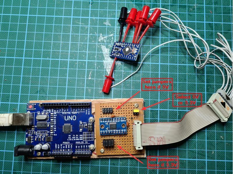
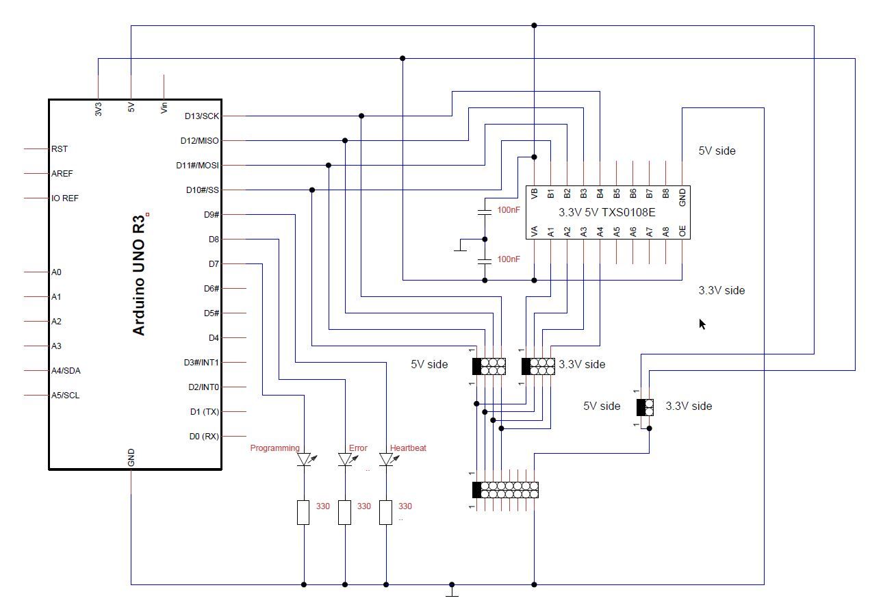
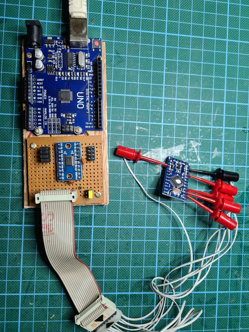
      You must program the bootloader with an ISP. I used my β€˜Arduino as ISP’. See https://forum.mysensors.org/topic/11444/using-an-arduino-uno-as-isp-for-programming-5v-and-3-3v-boards-without-soldering-the-needed-connections

      Remark
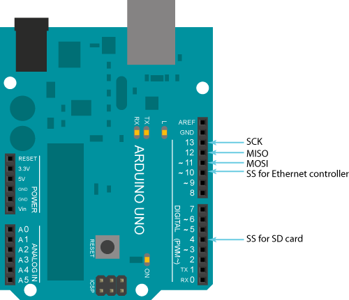
      If your pro mini is already connected to the RFM69HW radio, D11, D12 and D13 are used as MISO, MOSI and SCK for the radio.
      These pins are also used to program the bootloader.
      This will affect each other. The ISP programmer will not be able to detect the device ID and will fail. You must disconnect these 3 lines from the radio module, the time to (re)program the bootloader.

      20201111_171045.jpg

      You can find the used sketch at https://github.com/ericvb/MySensorsArduinoSketches/tree/master/sketches/ArduinoProMiniLockDoorBatterySensorWithEncryptionGithub

      So in a nutshell:

      1. first program the bootloader via minicore (Arduino IDE : burn bootloader)
      2. download the sketch via your normal USB to TTL programmer using the rx, tx, dtr, gnd pins (Arduino IDE : Upload)

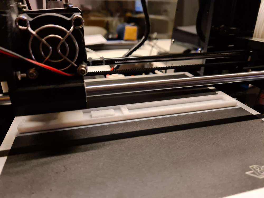
      The battery-based windows/door sensor node : 3D printing enclosure

      Because I had to use the cover of the cable duct as base for the Pro Mini, I decided to design a case with approximately the same dimensions.
      The dimensions were dictated by the available space in the PVC door frame, the dimensions of the Pro Mini, the RFM69HW, the 2 AA batteries and the minimum possible printed thickness still solid by my 3D printer:

      • Length : 200mm
      • Width: 20mm
      • Height: 17mm

      You can find the design (open source FreeCAD) and STL files at: https://www.thingiverse.com/thing:4659402
      The last months the thingiverse website has many problems, designs are not visible, 404 messages, etc.
      Post a note if you don't find the 'thing'

      20201105_211946.jpg
      20201106_091734.jpg
      20201112_131521.jpg
      20201114_133327.jpg
      20201114_161832.jpg
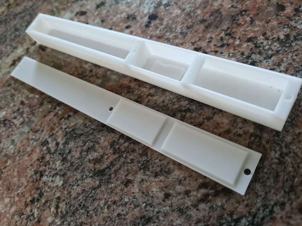
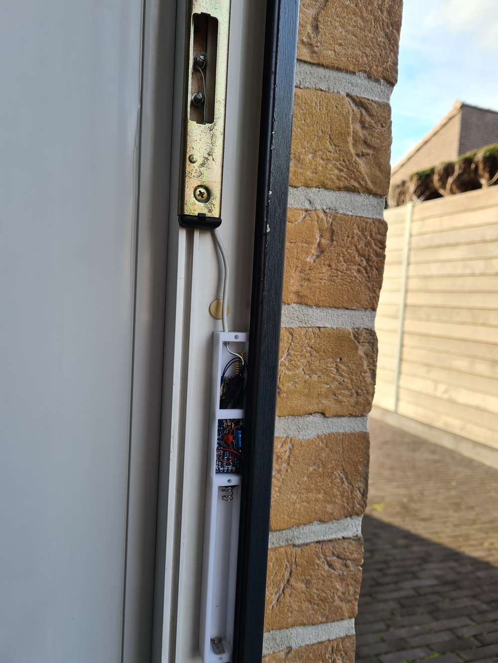
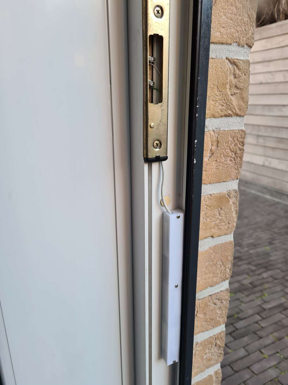
      The sensor is fastened with Velcro strips to prevent damage to the door caused by using fixing screws.

      References

      Via following links, you can find more information about minimal power consumption, bootloaders, etc.
      Low power Pro Mini

      https://www.mysensors.org/build/battery
      https://forum.mysensors.org/topic/2067/my-slim-2aa-battery-node
      https://forum.mysensors.org/topic/486/my-2aa-battery-sensor
      https://iot-playground.com/blog/2-uncategorised/10-low-power-door-window-sensor
      https://iot-playground.com/blog/2-uncategorised/9-arduino-low-power-sensor
      http://www.gammon.com.au/power
      https://www.iot-experiments.com/arduino-pro-mini-power-consumption/
      https://forum.pimatic.org/topic/383/tips-battery-powered-sensors/

      Battery consumption

      https://forum.mysensors.org/topic/10426/ds18b20-on-2xaaa-battery
      https://andreasrohner.at/posts/Electronics/How-to-modify-an-Arduino-Pro-Mini-clone-for-low-power-consumption/

      Specific commercial hardware

      https://www.canique.com (power efficient board with RFM69HW)
      https://www.tindie.com/stores/easysensors/
      https://www.tindie.com/products/vysocan/rfm69-radio-node-mini/

      Use of bootloaders

      https://www.iot-experiments.com/arduino-pro-mini-1mhz-1-8v/
      https://forum.mysensors.org/topic/7296/how-to-burn-fuses-so-that-pro-mini-3-3v-would-go-down-to-1-8v-solved/17
      https://forum.mysensors.org/topic/3018/tutorial-how-to-burn-1mhz-8mhz-bootloader-using-arduino-ide-1-6-5-r5
      https://forum.mysensors.org/topic/3657/mymultisensors/144
      https://forum.mysensors.org/topic/5478/how-to-get-longest-battery-life/42

      posted in My Project
      evb
      evb
    • Security: Signing messages and Encryption of messages: a guide? or more a summary of my tests?

      This post is a try to order my thoughts about the mysensors implementation possibilities for signing and encryption.

      I thought that it could be of some help for other people, who are new, like me, to mysensors and want to start using it.
      This is written with in mind the current version 2.3.1 of the mysensors libary and 2 Arduinos Uno's R3 as hardware. Be aware that this can change in the future as the library will continue to evolve!

      Please, if you find any mistakes, don't hesitate to point them out to me so I can correct this post.

      First some (condensed) theory found in the docs and on this forum.

      Two different things:

      • Signing messages : this makes that the receiver is sure that the received message is really from the transmitter. The message can't be changed by somebody during the transmission of the message. This is done by the MySensors message protocol.
        More detailed explication can be found on: https://www.mysensors.org/apidocs/group__MySigninggrpPub.html#MySigninggrpencryption

      • Encryption of the messages: is done on the level of the used radio itself. For RFM69HW for example, it is done by the hardware itself of the radio. It is independent from the MySensors message protocol implementation.

      A. Signing of the messages

      Three possibilities: 2 based on software and one based on extra external hardware. The latest I can't test because I have no Atmel ATSHA204 chips lying around...

      • First option, software backed by using only a password : weaker security, but simple to activate.

        MY_SIGNING_SIMPLE_PASSWORD: this keyword enables security only on the level signing
        If the provided password is shorter than the size of the HMAC key, it will be null-padded to accommodate the key size in question. A 32 character password is the maximum length. Any password longer than that will be truncated.

      • Second option, sofware backed

        MY_SIGNING_SOFT: this keyword enables security only on the level signing

        If MY_SIGNING_SIMPLE_PASSWD is used a personalisation must not be done.
        If not used, a personalization must be done, the values are stored in EEPROM.(see: https://www.mysensors.org/apidocs-beta/group__MySigninggrpPub.html#personalization). See also further on.

      • Third option, hardware backed via the Atmel ATSHA204 chip

        MY_SIGNING_ATSHA204: this keyword enables security only on the level signing

        If MY_SIGNING_SIMPLE_PASSWD is used a personalisation must not be done.
        If not used, a personalization must be done, the values are written to the Atmel ATSHA204 ship. It is irreversible!! (see https://www.mysensors.org/apidocs-beta/group__MySigninggrpPub.html#personalization)

      B. Encryption of the radio transport level

      Only possible for the supported radios (RF24, RFM69, NRF5, RFM95 at current library version 2.3.1)(https://www.mysensors.org/apidocs-beta/group__EncryptionSettingGrpPub.html)
      The RFM69 radio does support hardware encryption of the communication using AES (Advanced Encryption Standard).

      • MY_ENCRYPTION_SIMPLE_PASSWORD: this keyword enables encryption on all radio communications of the radio types that supports it and uses provided password as key.
        If the provided password is shorter than the size of the AES key, it will be null-padded to accommodate the key size in question. A 16 character password is the maximum length. Any password longer than that will be truncated.
        example : #define MY_ENCRYPTION_SIMPLE_PASSWD "MyInsecurePassword"

      If you are already using the first option of signing messages (MY_SIGNING_SIMPLE_PASSWORD), you can replace it by following keyword:

      • MY_SECURITY_SIMPLE_PASSWORD: this keyword enables security on the level signing and encryption (only usable on Arduino. On the Raspberry PI use the other two simple options)

      My practical tests

      • a sensor based on an Arduino Uno with the sketch UltraSonic_sensor from the website adapted for the RFM69HW radio
      • a gateway based on an Arduino, a W5100 ethernet shield for the Uno and a radio RFM69HW (see https://forum.mysensors.org/topic/10358/solved-mqtt-gateway-based-on-arduino-uno-uno-compatible-w5100-ethernet-shield-rfm69hw-radio)
      1. Added in the two sketches: only encryption
      #define MY_ENCRYPTION_SIMPLE_PASSWORD "my16characterpassword"
      
      Result : it works
      
      1. Added in the two sketches: encryption and simple signing
      #define MY_ENCRYPTION_SIMPLE_PASSWORD "my16characterpassword"
      #define MY_SIGNING_SIMPLE_PASSWORD "my32characterpassword"
      
      Result : warning when downloading the code into the gateway: "Low memory available, stability problems may occur."
      It doesn't work!
      
      1. Added in the two sketches: encryption and simple signing
      #define MY_ENCRYPTION_SIMPLE_PASSWORD "my16characterpassword"
      #define MY_SIGNING_SIMPLE_PASSWORD "my16characterpassword"
      
      Result : warning when downloading the code into the gateway: "Low memory available, stability problems may occur."
      It doesn't work!
      
      1. Added in the two sketches: the shortcut define for the Arduino platform
      #define MY_SECURITY_SIMPLE_PASSWORD "my16characterpassword"
      
      Result : it works
      
      1. Added in the two sketches: the shortcut define for the Arduino platform
      #define MY_SECURITY_SIMPLE_PASSWORD "my32characterpassword"
      
      Result : it works
      

      Is this shortcut define specially done for the Arduino platform to avoid the low memory condition?

      1. Added in the two sketches : encryption and soft signing with simple password personalization
      //enable radio communication encryption
      #define MY_ENCRYPTION_SIMPLE_PASSWD "my16characterpassword"
      #define MY_SIGNING_SIMPLE_PASSWD "my32characterpassword"
      #define MY_SIGNING_SOFT
      #define MY_SIGNING_REQUEST_SIGNATURES
      #define MY_SIGNING_SOFT_RANDOMSEED_PIN A0
      
      Result : warning when downloading the code into the gateway: "Low memory available, stability problems may occur."
      It doesn't work. The signing is failing.
      
      1. Added in the two sketches : encryption and soft signing with personalization
        First we will personalize each arduino (the sensor and the gateway)
      • open the SecurityPersonalizer.ino file via the Arduino IDE menu File, Examples, Mysensors, SecurityPersonalizer
      • uncomment the define GENERATE_KEYS_SOFT
      • upload the sketch to your Arduino
      • open the serial monitor
      • here you will find your generated keys HMAC and AES keys
      • copy the entries under the 'Key copy section' into the SecurityPersonalizer.ino file
      • comment again the define GENERATE_KEYS_SOFT

      The following 3 steps must be done on each node where you want to use soft signing

      • uncomment the define PERSONALIZE_SOFT
      • upload the sketch again to your Arduino
      • in the serial monitor output you will find now that the keys are written to the EEPROM (see EEPROM section)

      The following 5 steps must also be done on each node where you want to use whitelisting

      • if you want to use whitelisting and your device does not provide a unique device ID, you have to generate a unique serial and store it in EEPROM (my arduino uno does not provide a unique device ID, so I must run the sketch)

      • comment the define PERSONALIZE_SOFT

      • uncomment the define PERSONALIZE_SOFT_RANDOM_SERIAL

      • upload the sketch to your Arduino

      • in the serial monitor output you will find now a generated serial unique device ID. This unique serial ID must be copied somewhere on a safe place. You must later on copy this key in the whitelisting define of your gateway and nodes sketches.

      • Take now your sketches and add the following defines

      //enable radio communication encryption
      #define MY_ENCRYPTION_SIMPLE_PASSWD "my16characterpassword"
      //enable soft signing
      #define MY_SIGNING_SOFT
      #define MY_SIGNING_REQUEST_SIGNATURES
      #define MY_SIGNING_SOFT_RANDOMSEED_PIN A0
      #define MY_SIGNING_NODE_WHITELISTING {{.nodeId = 0,.serial = {0x11,0x22,0x33,0x44,0x55,0x66,0x77,0x88,0x99}},{.nodeId = 1,.serial = {0x99,0x88,0x77,0x66,0x55,0x44,0x33,0x22,0x11}}}
      

      The MQTT gateway has always nodeid = 0 and my sensor has nodeid = 1 (the sensors must have a fixed set nodeid because in MQTT mode, the controller (like HomeAssistant) can't assign node ids).
      The serials given above are fake numbers, use the ones from your sketch!

      Result : warning when downloading the code into the gateway: "Low memory available, stability problems may occur."
      It doesn't work!
      

      So I think that in my case, with an Arduino Uno as MQTT gateway, only the simple signing and encryption is possible.
      Maybe the hardware backed signing, but I can't test this at this moment. (see my other question : https://forum.mysensors.org/topic/10370/is-there-still-a-breakout-board-for-the-atmel-atsha204a-chip)

      posted in General Discussion
      evb
      evb
    • RE: [SOLVED] Arduino mZero clone RobotDyn SAMD21 M0 board with RFM69HW sending but not receiving parent response

      Apparently this day is my lucky day πŸ™‚

      @scalz , you did me think with your comment about the samd21 board not triggering the irq.

      So I looked up where the pin layouts of all these 'arduino compatible' boards are defined.
      My used board is a RobotDyn Samd21 M0 board and they claim compatible with a Arduino M0 and I did use the Arduino SAMD boards (32-bits ARM Cortex-M0+) by Arduino version 1.8.3.
      The code you find at: https://github.com/arduino/ArduinoCore-samd
      With some help of the google doctor, I did find that the pin layouts are defined in the Variants.cpp file in
      https://github.com/arduino/ArduinoCore-samd/blob/master/variants/arduino_mzero/variant.cpp
      (I'm using the Arduino M0 entry when selecting my board)
      In this file

      /*
       *
       * + Pin number +  ZERO Board pin  |  PIN   | Label/Name      | Comments (* is for default peripheral in use)
       * +------------+------------------+--------+-----------------+------------------------------
       * |            | Digital Low      |        |                 |
       * +------------+------------------+--------+-----------------+------------------------------
       * | 0          | 0 -> RX          |  PA11  |                 | EIC/EXTINT[11] ADC/AIN[19] PTC/X[3] *SERCOM0/PAD[3] SERCOM2/PAD[3] TCC1/WO[1] TCC0/WO[3]
       * | 1          | 1 <- TX          |  PA10  |                 | EIC/EXTINT[10] ADC/AIN[18] PTC/X[2] *SERCOM0/PAD[2] TCC1/WO[0] TCC0/WO[2]
       * | 2          | ~2               |  PA08  |                 | EIC/NMI ADC/AIN[16] PTC/X[0] SERCOM0/PAD[0] SERCOM2/PAD[0] *TCC0/WO[0] TCC1/WO[2]
       * | 3          | ~3               |  PA09  |                 | EIC/EXTINT[9] ADC/AIN[17] PTC/X[1] SERCOM0/PAD[1] SERCOM2/PAD[1] *TCC0/WO[1] TCC1/WO[3]
       * | 4          | ~4               |  PA14  |                 | EIC/EXTINT[14] SERCOM2/PAD[2] SERCOM4/PAD[2] TC3/WO[0] *TCC0/WO[4]
       * | 5          | ~5               |  PA15  |                 | EIC/EXTINT[15] SERCOM2/PAD[3] SERCOM4/PAD[3] TC3/WO[1] *TCC0/WO[5]
       * | 6          | ~6               |  PA20  |                 | EIC/EXTINT[4] PTC/X[8] SERCOM5/PAD[2] SERCOM3/PAD[2] TC7/WO[0] *TCC0/WO[6]
       * | 7          | ~7               |  PA21  |                 | EIC/EXTINT[5] PTC/X[9] SERCOM5/PAD[3] SERCOM3/PAD[3] TC7/WO[1] *TCC0/WO[7]
       * +------------+------------------+--------+-----------------+------------------------------
       * |            | Digital High     |        |                 |
       * +------------+------------------+--------+-----------------+------------------------------
       * | 8          | ~8               |  PA06  |                 | EIC/EXTINT[6] PTC/Y[4] ADC/AIN[6] AC/AIN[2] SERCOM0/PAD[2] *TCC1/WO[0]
       * | 9          | ~9               |  PA07  |                 | EIC/EXTINT[7] PTC/Y[5] DC/AIN[7] AC/AIN[3] SERCOM0/PAD[3] *TCC1/WO[1]
       * | 10         | ~10              |  PA18  |                 | EIC/EXTINT[2] PTC/X[6] SERCOM1/PAD[2] SERCOM3/PAD[2] *TC3/WO[0] TCC0/WO[2]
       * | 11         | ~11              |  PA16  |                 | EIC/EXTINT[0] PTC/X[4] SERCOM1/PAD[0] SERCOM3/PAD[0] *TCC2/WO[0] TCC0/WO[6]
       * | 12         | ~12              |  PA19  |                 | EIC/EXTINT[3] PTC/X[7] SERCOM1/PAD[3] SERCOM3/PAD[3] *TC3/WO[1] TCC0/WO[3]
       * | 13         | ~13              |  PA17  | LED             | EIC/EXTINT[1] PTC/X[5] SERCOM1/PAD[1] SERCOM3/PAD[1] *TCC2/WO[1] TCC0/WO[7]
       * | 14         | GND              |        |                 |
       * | 15         | AREF             |  PA03  |                 | *DAC/VREFP PTC/Y[1]
       * | 16         | SDA              |  PA22  |                 | EIC/EXTINT[6] PTC/X[10] *SERCOM3/PAD[0] SERCOM5/PAD[0] TC4/WO[0] TCC0/WO[4]
       * | 17         | SCL              |  PA23  |                 | EIC/EXTINT[7] PTC/X[11] *SERCOM3/PAD[1] SERCOM5/PAD[1] TC4/WO[1] TCC0/WO[5]


      This is the defined pin mapping for a Arduino mZero. (I was using D2 as IRQ for the RFM69)

      * | 2          | ~2               |  PA08  |
      

      But on the pin layout of the RobotDyn board I saw:

      * | 2          | ~2               |  PA14  |
      

      On the RobotDyn the pin PA08 is mapped on the D4 arduino pin and not the D2 pin!
      With the pins D2/D4, RobotDyn is following here the Arduino Zero layout and NOT the Arduino mZero layout!

      So, I verified the other mappings and found that following pins are different mapped on the Arduino mZero:

       * | 2          | ~2               |  PA08  | 
       
       * | 4          | ~4               |  PA14  | 
      

      On the RobotDyn Samd21M0

       * | 2          | ~2               |  PA14  | 
      
       * | 4          | ~4               |  PA08  | 
      

      So I changed the IRQ (DIO0) from the RF69 to the port D8 (PA06) and bingo it started to work πŸ™‚ (did choose randomly D8)

      I saw also a difference in the SPI mapping
      mZero

       * | 18         | 1                |  PA12  | MISO 
      

      RobotDyn samd21 m0

       * |  not defined on their pin layout doc       | 1                |  PB12  | MISO 
      

      But it is working, so maybe an error on RobotDyn's documentation?

      So if I resume the thing:
      The RobotDyn SAMD21 M0 board is claimed compatible with the Arduino M0 (mZero). In the IDE you must also select the Arduino M0. (selecting Arduino/Genuino Zero xxx will not work)
      But the RobotDyn used layout is compatible with the Arduino Zero, so pin D2 and D4 are reversed, making the code of the board Arduino M0 not working if you choose to use these pins in your design.

      So now we can continue to build our gateway, my originally goal.
      Edit : my MQTT gateway with the RobotDyn Samd21 M0 board, a W5500 ethernet module and a radio RFM69HW is up and running πŸ™‚

      Thanks for all comments that guided me to the solution πŸ™‚

      posted in Troubleshooting
      evb
      evb
    • RE: [SOLVED] MQTT gateway based on Arduino Uno - Uno compatible W5100 Ethernet shield - RFM69HW radio

      Nobody has never build a gateway based on an Arduino Uno, a W5100 shield and a RFM69HW?

      So I will answer my own questions πŸ™‚
      I did take my chance and choose to build first a gateway version using the hardware SPI bus (no soft spi) and I was lucky, it worked directly! So no need to try the soft-spi version.

      Because I did already build previously a sensor (https://www.mysensors.org/build/distance), I had all hardware already ready to be used.

      So what is the used hardware?

      • one standard Arduino Uno R3 (guine or chinese clone, DON'T BUY WAVGAT arduino uno types, they require specific hardware drivers in the Arduino IDE and this manufacturer doesn't update his own old drivers!!)(https://www.aliexpress.com/item/1pcs-Smart-Electronics-high-quality-UNO-R3-MEGA328P-CH340G-Compatible-NO-USB-CABLE-for-arduino/32830661533.html)
      • one RFM69HW, version 868MHz (check what you can use at your country!)(https://www.aliexpress.com/item/Free-Shipping-RFM69HW-868Mhz-Transceiver-Module-High-Integrated-HopeRF-Wireless-868S2-Module-SPI-1-8-3/32810316806.html)
      • one helical antenna (https://www.aliexpress.com/item/10PCS-868MHz-Helical-Antenna-2-15dBi-13mm-Stable-for-Remote-Contorl/32668155368.html)
      • one W5100 shield pin compatible with an Arduino Uno (https://www.aliexpress.com/item/Free-Shipping-UNO-Shield-Ethernet-Shield-W5100-R3-UNO-Mega-2560-1280-328-UNR-R3-only/32502588687.html)
      • one proto shield to build the RFM69HW radio on top of the W5100 shield (https://www.aliexpress.com/item/Standard-Proto-Screw-Shield-Board-For-Arduino-Compatible-Improved-version-support-A6-A7-Diy-Kit-Electronic/32832054800.html)
      • one logic channel convertor between Arduino 5V and RFM69HW radio 3.3V (https://www.aliexpress.com/item/3-3V-5V-TXS0108E-8-Channel-Logic-Level-Bi-directional-Converter-Module-TXB0108-Mutual-Convert-Module/32916020205.html)

      The hardware is wired following next schematic:
      0_1556974214950_Arduino Uno Ethernet Gateway.png

      Connecting the RFM69HW hardware was somewhat tricky. The used pin headers on the RFM69HW are not following the standard spaced 2.54mm pin headers like on the Arduino print. I did not have a converter plate, so I soldered some hard wire into the RFM69HW pins and bend them into the pin holes from the protoboard. See photo.
      0_1556974628264_DSC_1460.JPG
      So what about the software:

      • Arduino IDE version 1.8.9
      • MySensors library 2.3.1

      I did take as base the sketch found on the website https://www.mysensors.org/build/mqtt_gateway or https://github.com/mysensors/MySensors/blob/master/examples/GatewayW5100MQTTClient/GatewayW5100MQTTClient.ino

      Important is to configure the specific RFM69 defines
      #define MY_RADIO_RFM69
      #define MY_RFM69_FREQUENCY RFM69_868MHZ // Set your frequency here
      #define MY_IS_RFM69HW // Omit if your RFM is not "H"
      #define MY_RFM69_NEW_DRIVER

      When the W5100 Arduino shield is connected we have to move SS (slave select) pin for the RFM69 radio because the shield is using the default D10
      #define MY_RFM69_CS_PIN 6

      /*
       * The MySensors Arduino library handles the wireless radio link and protocol
       * between your home built sensors/actuators and HA controller of choice.
       * The sensors forms a self healing radio network with optional repeaters. Each
       * repeater and gateway builds a routing tables in EEPROM which keeps track of the
       * network topology allowing messages to be routed to nodes.
       *
       * Created by Henrik Ekblad <henrik.ekblad@mysensors.org>
       * Copyright (C) 2013-2019 Sensnology AB
       * Full contributor list: https://github.com/mysensors/MySensors/graphs/contributors
       *
       * Documentation: http://www.mysensors.org
       * Support Forum: http://forum.mysensors.org
       *
       * This program is free software; you can redistribute it and/or
       * modify it under the terms of the GNU General Public License
       * version 2 as published by the Free Software Foundation.
       *
       *******************************
       *
       * REVISION HISTORY
       * Version 1.0 - Henrik Ekblad
       * Version 1.1 - Eric Van Bocxlaer
       *
       * DESCRIPTION
       * The W5100 MQTT gateway sends radio network (or locally attached sensors) data to your MQTT broker.
       * The node also listens to MY_MQTT_TOPIC_PREFIX and sends out those messages to the radio network
       *
       * LED purposes:
       * - To use the feature, uncomment WITH_LEDS_BLINKING in MyConfig.h
       * - RX (green) - blink fast on radio message received. In inclusion mode will blink fast only on presentation received
       * - TX (yellow) - blink fast on radio message transmitted. In inclusion mode will blink slowly
       * - ERR (red) - fast blink on error during transmission error or receive crc error
       *
       * See http://www.mysensors.org/build/esp8266_gateway for wiring instructions.
       * nRF24L01+  ESP8266
       * VCC        VCC
       * CE         GPIO4
       * CSN/CS     GPIO15
       * SCK        GPIO14
       * MISO       GPIO12
       * MOSI       GPIO13
       *
       * Not all ESP8266 modules have all pins available on their external interface.
       * This code has been tested on an ESP-12 module.
       * The ESP8266 requires a certain pin configuration to download code, and another one to run code:
       * - Connect REST (reset) via 10K pullup resistor to VCC, and via switch to GND ('reset switch')
       * - Connect GPIO15 via 10K pulldown resistor to GND
       * - Connect CH_PD via 10K resistor to VCC
       * - Connect GPIO2 via 10K resistor to VCC
       * - Connect GPIO0 via 10K resistor to VCC, and via switch to GND ('bootload switch')
       *
        * Inclusion mode button:
       * - Connect GPIO5 via switch to GND ('inclusion switch')
       *
       * Hardware SHA204 signing is currently not supported!
       *
       * Make sure to fill in your ssid and WiFi password below for ssid & pass.
       * 
       * ***************************************************************************************************************
       * Connection with RFM69HW and EthernetShieldW5100 through the SPI bus (Serial Peripheral Interface)
       * On this bus we can have only one master (= the Arduino Uno) and different slaves (= the W5100 and the RFM69HW).
       * The master can only talk to one slave each time!
       * 
       * RFM69HW    Uno R3    EthernetShieldW5100(autowired)
       * VCC 3.3V   VCC 3.3V  
       *            VCC 5.0V  VCC 5.0V
       * DIO0       D2/INT0
       * NSS        D6
       * SCK        D13/SCK   SCK (D13)
       * MISO       D12/MISO  MISO (D12)
       * MOSI       D11/MOSI  MOSI (D11)
       *            D4        SS (sd-card)
       *            D10/SS    SS (W5100)(Default in ethernet library: do not wire different with a no shield version!)
       *            
       * 
       * NSS/SS : Slave Select for SPI bus (the master selects with which slave he want to talk)
       * SCK : serial clock signal delivered by the master
       * MISO : Master Input Slave Output (arduino receives data from the slave)
       * MOSI : Master Output Slave Input (arduino sends data to the slave)
       */
      
      
      // Enable debug prints to serial monitor
      //#define MY_DEBUG
      // Enable specific RFM69 debug prints to serial monitor
      //#define MY_DEBUG_VERBOSE_RFM69
      
      // Enables and select radio type (if attached)
      //#define MY_RADIO_RF24
      //#define MY_RADIO_RFM95
      #define MY_RADIO_RFM69
      #define MY_RFM69_FREQUENCY RFM69_868MHZ // Set your frequency here
      #define MY_IS_RFM69HW // Omit if your RFM is not "H"
      #define MY_RFM69_NEW_DRIVER
      
      #define MY_GATEWAY_MQTT_CLIENT
      
      // Set this node's subscribe and publish topic prefix
      #define MY_MQTT_PUBLISH_TOPIC_PREFIX "mygateway1-out"
      #define MY_MQTT_SUBSCRIBE_TOPIC_PREFIX "mygateway1-in"
      
      // Set MQTT client id
      #define MY_MQTT_CLIENT_ID "mysensors-1"
      
      // Enable gateway ethernet module type : not needed here because MY_GATEWAY_MQTT_CLIENT defines already the use of W5100
      //#define MY_GATEWAY_W5100
      #define SD_SS_PIN (4)  // chip-select for SD card (normally unused, pull high!, see code!) 
      
      // W5100 Ethernet module SPI enable (this setting is optional if using a shield/module that manages SPI_EN signal)
      //#define MY_W5100_SPI_EN 4
      
      // Enable Soft SPI for NRF radio (note different radio wiring is required)
      // The W5100 ethernet module seems to have a hard time co-operate with
      // radio on the same spi bus.
      // Situation on 2019-05-04: with the new RFM69HW driver this is not true anymore for a radio RFM69!
      //#if !defined(MY_W5100_SPI_EN) && !defined(ARDUINO_ARCH_SAMD)
      //#define MY_SOFTSPI
      //#define MY_SOFT_SPI_SCK_PIN 14
      //#define MY_SOFT_SPI_MISO_PIN 16
      //#define MY_SOFT_SPI_MOSI_PIN 15
      //#endif
      
      // When W5100 shield is connected we have to move SS (slave select) pin for the RFM69 radio because the shield
      // is using the default D10
      #define MY_RFM69_CS_PIN 6
      
      // When W5100 is connected we have to move CE/CSN pins for NRF radio
      //#ifndef MY_RF24_CE_PIN
      //#define MY_RF24_CE_PIN 5
      //#endif
      //#ifndef MY_RF24_CS_PIN
      //#define MY_RF24_CS_PIN 6
      //#endif
      
      // Enable these if your MQTT broker requires username/password
      //#define MY_MQTT_USER "username"
      //#define MY_MQTT_PASSWORD "password"
      
      // Enable MY_IP_ADDRESS here if you want a static ip address (no DHCP)
      //#define MY_IP_ADDRESS 192,168,178,87
      
      // If using static ip you can define Gateway and Subnet address as well
      //#define MY_IP_GATEWAY_ADDRESS 192,168,178,1
      //#define MY_IP_SUBNET_ADDRESS 255,255,255,0
      
      // MQTT broker ip address or url. Define one or the other.
      //#define MY_CONTROLLER_URL_ADDRESS "m20.cloudmqtt.com"
      #define MY_CONTROLLER_IP_ADDRESS 192, 168, 178, 68
      
      // The MQTT broker port to to open
      // With simple arduino uno's we can't use encrypted communication!
      #define MY_PORT 1883
      
      /*
      // Enable inclusion mode
      #define MY_INCLUSION_MODE_FEATURE
      // Enable Inclusion mode button on gateway
      //#define MY_INCLUSION_BUTTON_FEATURE
      // Set inclusion mode duration (in seconds)
      #define MY_INCLUSION_MODE_DURATION 60
      // Digital pin used for inclusion mode button
      //#define MY_INCLUSION_MODE_BUTTON_PIN  3
      
      // Set blinking period
      #define MY_DEFAULT_LED_BLINK_PERIOD 300
      
      // Flash leds on rx/tx/err
      // Uncomment to override default HW configurations
      //#define MY_DEFAULT_ERR_LED_PIN 16  // Error led pin
      //#define MY_DEFAULT_RX_LED_PIN  16  // Receive led pin
      //#define MY_DEFAULT_TX_LED_PIN  16  // the PCB, on board LED
      */
      
      #include <Ethernet.h>
      #include <MySensors.h>
      
      void before() {
          pinMode(SD_SS_PIN, OUTPUT);
          digitalWrite(SD_SS_PIN, HIGH); 
      }
      
      void setup()
      {
          // Setup locally attached sensors
      }
      
      void presentation()
      {
          // Present locally attached sensors here
      }
      
      void loop()
      {
          // Send locally attached sensors data here
      }
      

      I hope that this will be helpful for some people trying to build something equivalent πŸ™‚

      posted in Hardware
      evb
      evb
    • RE: Advisory: put IOT devices on a separate LAN/vLAN for better security

      @NeverDie my setup consists of the mandatory modem/router from my internet provider with a Zywall 110 behind it and then a managed NETGEAR switch. The provider's modem/router acts only as a conduit.

      All my wifi enabled IOT devices like the heating, the energy Smappee, the sonoff modified ESPHome switches, etc are connected via a wifi access point to the specific IOT VLAN.
      The MQTT VM server for the MySensors environment is also connected to the same VLAN.

      Specific rules in the Zywall are permitting internet access for specific IP's on the VLAN. For example the heating, Smappee, the rituals dispenser, ... have internet access because they are cloud based vendor applications.

      The controller HomeAssistant is running in the normal LAN and has a specific firewall rule to allow access to the VLAN.
      Another rule is allowing only my desktop computer to access the VLAN for admin tasks like updating devices, etc

      The question is all about how far you want to go in protecting your network.
      There are still weak points in my setup. You can say that each firewall rule is a potential weak point...
      For example the smartTV and the Bose Touch speakers are in the normal LAN because I'm playing video and music from my NAS. But they are also IOT devices...
      Because I have touch screens with the home assistant (HA) GUI, the home assistant sits in the normal LAN.
      I want also be able to consult HA on my smartphone, etc.

      It's like securing your home, make it more secure than your neighbor and they will give up and visit him πŸ˜‰

      posted in General Discussion
      evb
      evb
    • RE: RFM69 Range issues

      @skywatch Thanks for wanting to help me.
      I have also the SDR# software installed, but was getting quicker a visual result with the other software, that's why I used this software.
      So I'm curious how to set my sdr to the optimum level by adjusting the gain.
      2021-01-17 22_37_55-AIRSPY SDR# Studio v1.0.0.1784 - RTL-SDR USB (Original).png

      For photo's you can see them here : https://forum.mysensors.org/topic/11499/checking-mechanical-locked-doors-by-a-battery-based-windows-door-sensor-node
      At the end, you have photos of the problem node.

      Like said, today, the node was working.
      I've reprogrammed also the repeater node, because I was doing a new temperature repeater node and remarked that my sketch code of the first repeater node was missing my encryption key???
      I don't know what did happen here. The repeater node was recognized by the gateway and the controller, so the used encryption key is normally correct. Or is a presentation message not encrypted???
      Maybe I did a mistake in saving my github sketch where I delete my keys of course 😲 πŸ€”
      To be sure, I reprogrammed the repeater node with the correct encryption key.

      If it happens again, I will check the spectrum and in case it isn't sending something, I will check the node on soldering errors and move also the node upwards in the doorframe.

      I will check also the MySensors docs to see how we can see if a repeater node is working and how we can see that a sensor node is using the repeater and not trying to send directly to the gateway.

      posted in Troubleshooting
      evb
      evb
    • RE: Filter node

      @Snyfir another approach is to use another radio channel for your B network? That includes of course another gateway also...
      An advantage is that you can stick with the standard MySensors library.
      More information on : https://www.mysensors.org/download/sensor_api_20 : search channel

      of course:
      That’s why I want nodes of network (A) use only repeaters of network (A), and nodes of network (B) use repeaters of networks (A) and (B)
      This will not be possible....

      posted in Feature Requests
      evb
      evb
    • Using an Arduino Uno as ISP for programming 5V and 3.3V boards without soldering the needed connections

      I needed a programmer quickly and because ordering one, would take too much time, I went the way of using an Arduino as ISP.

      Programming another Uno, for example, is not difficult, you will find tutorials all over the net. The Uno's have soldered connectors, so you can use Dupont cables to do the needed connections.
      If you have a Pro Mini 3.3V 8MHz, it is more complicated

      • problem of 5V (UNO) versus 3.3V (Pro Mini)
        In some forum posts you can read that you can program a 3.3V one with 5V because the used chip is the same. OkΓ©, that is maybe true, but what if you want to reprogram a Pro Mini with other connected 3.3V only hardware?
      • how to connect the needed cables if you don't want to solder? (de-soldering a header is not one of my favorite activities, neither cleaning the solder holes πŸ˜‰ )

      One solution I found when Googling was this one: https://create.arduino.cc/projecthub/user3330224/programming-the-arduino-pro-mini-without-soldering-pins-7d033d from Ruben Zilzer.
      I printed his 'clothes pins', but the problem are the used header pins. You must put solder on it to make sure that the connection is done. This must be done very accurately, because all pins must make good contact with the board. If you have one of them that has a lower soldering than the others, these others don't make contact and it doesn't work properly. 😞
      Imagine, to program a Pro Mini I used another Pro Mini, so in total 4 clothes pins.
      I've done my best but I didn't manage to have each time a good contact between the 2 Arduino's.
      Conclusion: a good idea, but unfortunately not reliable.

      So, I searched the internet further on, but didn't find a reliable solution...

      Until suddenly I remembered a very old, I think Elektor?, project, to build your own digital scope. Times when buying such a thing was outside everyone's personal budget.
      Mini measuring clips were used to connect the scope to the DUT thing.
      meetclips.jpg
      If I used these clips to do the connections?
      I even found back this old project and could re-use the existing measure clips together with the flat cable, a profound stroke of luck πŸ™‚
      ArduinoUnoIspWithLogicalLeveling.jpg
      To solve the 5V to 3.3V problem, I did use the 8-Bit Bidirectional Voltage-Level Shifter TXS0108E. To make it configurable, I used jumpers.
      See the following diagram
      ArduinoUnoAsIsp.jpg

      With the jumpers you select the needed voltage to program the target board.
      Because I used an Uno as programmer, I can simple connect the Uno to the computer via the build in USB connector. No USB-to-TTL programmer needed when using another Pro Mini to program a Pro Mini to avoid the voltage problem, with the used mini measuring clips I can program other Arduino boards, etc...

      Don't forget to uncomment #define USE_OLD_STYLE_WIRING in the ArduinoISP sketch in the examples to use the 'old style' connection like I did in my schema.

      Edit 2020-11-24
      (Re)Programming a Pro Mini with already connected hardware like a radio RFM69HW who uses also the pins D11(SCK), D12(MISO), D13(MOSI), can interfere with the ISP programmer. In one case, the Pro Mini was not correctly identified as a 328 device: β€œYikes! Invalid device signature”.
      The solution in that case, is to disconnect temporarily the external hardware.

      Maybe this can help other people struggling with the same problem... πŸ™‚

      posted in My Project
      evb
      evb
    • RE: Checking mechanical locked doors by a battery-based windows/door sensor node

      We are approximately 2 years later, a little follow-up πŸ™‚

      I had already noticed for a week of so that my 3 oldest sensors (including my prototype sensor) were no longer sending their status consistently. After checking the reported battery levels of the sensors I saw that there were around 50%, so that was normal... (50 % of 3V is 1.5V πŸ™‚ , below the BOD of 1.8V)

      So the sensors with this design worked for about 20 months on 2 normal AA batteries of 1.5 V, not bad πŸ™‚

      posted in My Project
      evb
      evb
    • [SOLVED] MQTT gateway based on Arduino Uno - Uno compatible W5100 Ethernet shield - RFM69HW radio

      Hi Folks,

      I'm new to MySensors, so before beginning building things, I read the docs, search the forum, etc., to be able to form me an idea how to start.

      First taking the docs: https://www.mysensors.org/build/ethernet_gateway and https://www.mysensors.org/build/mqtt_gateway

      The MQTT gateway is based on the ethernet gateway, so we are starting there.
      The recommandation is to use a W5100 Ethernet module. This module has problems sharing SPI with the radio, so it is proposed to use soft-spi for the radio.
      The W5100 ethernet shield module is hardware wired:
      0_1556721306433_arduino-ethernet-shield-pinout.png

      The radio should then be wired for soft-spi following the docs.
      Because there is no example for a RFM69HW, I imagine that we must follow the same schematic as for the NRF24L01 radio.

      The given sketch is based on the use of a NRF24L01 radio, so when searching for the correct settings for RFM69HW in the forum, I stumbled on plenty of topics of people trying to build the same thing.
      Some topics are already several years old, speaking about changing core ethernet libraries for the W5100 to disable the interrupts, others are building on forks of MySensors, forks of RFM69 library, etc.
      I saw also a remark in a topic that for using soft-spi, we should use the new RFM69 driver in the MySensors lib.
      In one of the topics with an own fork, was mentioned that, because the transactions in SPI where now supported in the RFM69 library, we can now wire also the RFM69HW radio to the same ports on the Arduino as the ethernet module.

      So, when reading all these topics, I did loose my view on the things 😞 :
      With the current version of the MySensors library (2.3.1)

      • must we use soft-spi like mentioned in the docs or hardware spi like found in topics on the forum?
      • https://forum.mysensors.org/topic/5109/solved-rfm69-based-nodes-unable-to-report-lib-version/45 : Are these forks now included into the main branch of MySensors?
      posted in Hardware
      evb
      evb
    • RE: difference between encryption with personalization and simple password

      In the past, I did several tests about signing and encryption.
      The results and my thoughts, you can find them here: https://forum.mysensors.org/topic/10382/security-signing-messages-and-encryption-of-messages-a-guide-or-more-a-summary-of-my-tests?_=1604220215583
      Maybe it can help πŸ™‚

      posted in Development
      evb
      evb
    • RE: Enclosure/Bumper for Easy/Newbie PCB

      For people searching the complete stl files of the box and the cover.
      I exported them again from the sketchup file.

      Hmm, how to upload files here? Only images are allowed by the server?
      I've uploaded them to my thingiverse place: https://www.thingiverse.com/thing:4694746

      Anyway, I will describe it too

      • download the sketchup zip file from the first post
      • dezip it and get the skp file
      • get an account on the Sketchup online website (free version)
      • open the sketchup file
      • export to stl via the menu at the left

      If you want the two parts apart, delete one of them in the sketchup designer and export the other. Don't save!!!
      Do undo and delete the other part. Export now the remaining part.

      posted in Enclosures / 3D Printing
      evb
      evb
    • RE: πŸ’¬ Distance Sensor

      @APL2017 Did you find the reason for this problem of reading periodically 0cm?
      I have the same problem with a Arduino Uno connected to a HC-SR04 sensor. (in reality I made two sensors and both have regularly 0cm as output)
      I can blindly adapt the software to filter out these strange values, but like you, I prefer to understand why this behaviour?

      posted in Announcements
      evb
      evb
    • RE: Reading INPUTS from arduino in domoticz

      Hi @Mati_Smart,
      Why are you using the relay actuator sketch if you want to read inputs?

      First rule in debugging things, is to narrow down the problem.
      Make your sketch to contain only the things you need.
      Verify if your sketch is meant to work with the hardware you are using.
      If the sketch is written originally for a Arduino Uno and you are using it on a Arduino Mega 2560, there is a chance that the used port numbers are not correct.
      For example I see that on a mega, the D20 and D21 pins are also pins used for SDA and SCL. Try to use first the normal digital pins, like D2, D3, ...

      posted in Hardware
      evb
      evb
    • An LCD node is polling the controller (Home Assistant) to get statuses of other nodes, a HOWTO.

      To get the status of different door nodes on my LCD node there are two methods:

      • direct node to node communication: The sending node is not only sending his status to the controller, but also directly to the LCD node
        In short the code in the door node for sending his status to the LCD node:
      #define LCD_NODE_ID 100
      #define LCD_CHILD_ID 4  //destination virtual child sensor of the LCD  node
      
      #define CHILD_ID 1  // Each radio node can report data for up to 254 different child sensors. You are free to choose the child id yourself.  You should avoid using child-id 255 because it is used for things like sending in battery level and other (protocol internal) node specific information.
      ...
      MyMessage msg(CHILD_ID,V_TRIPPED);
      MyMessage msgLCD(LCD_CHILD_ID, V_STATUS);
      

      Then in the loop method

           send(msg.set(value==HIGH ? 0 : 1)); // to the gateway ==> controller
           send(msgLCD.setDestination(LCD_NODE_ID).set(value==HIGH ? 0 : 1)); // send also to LCD node
      
      • by polling the controller to get the status of other sensors:
        You could do it only with node to node communication, but what if the distance it too long between the nodes to have a reliable connection? Some battery nodes are close to the gateway, but (too) far from the LCD node.
        Also the battery nodes are sleeping most of the time, so directly requesting them will not work!

      A node can request data from the controller or from a node.
      From the docs:

      bool request (const uint8_t childSensorId, const uint8_t variableType, const uint8_t destination = GATEWAY_ADDRESS)
      		
      Requests a value from gateway or some other sensor in the radio network. Make sure to add callback-method in begin-method to handle request responses.
      
      Parameters
      childSensorId	The unique child id for the different sensors connected to this Arduino. 0-254.
      variableType	The variableType to fetch
      destination	The nodeId of other node in radio network. Default is gateway
      Returns
      true Returns true if message reached the first stop on its way to destination.
      

      When requesting from the controller, there is no way to requesting data from another node. A node can only request data from itself.
      Workaround:

      • create child sensors (S_CUSTOM & V_CUSTOM) in the LCD node, one child sensor for each external node you want the status from and send these values to the controller.
      • get the controller so far that he is copying the statuses of the wanted nodes to these fields
      • request this data again from the controller (polling)

      How?
      See the sketch for detailed information (https://github.com/ericvb/MySensorsArduinoSketches/blob/master/sketches/ArduinoLCDDisplaySensorWithEncryptionGithub/ArduinoLCDDisplaySensorWithEncryptionGithub.ino), but in short

      • Present the child sensors in the LCD node
        // Register all sensors to gw (they will be created as child devices) by their ID and S_TYPE
        // for Home Assistant : S_CUSTOM together with V_CUSTOM
        present(LCD_CHILD_ID_pGarBike, S_CUSTOM);
        
      • Create only the first time the child devices in the loop (not sure anymore if this is really needed, was done during my tests). Put in comments after the first run!
        send(MyMessage(LCD_CHILD_ID_pGarBike,V_CUSTOM).set(1));
        
      • Let the controller copy the statuses from the other nodes in these child devices
      • Request the data from the controller
        request(LCD_CHILD_ID_pGarBike, V_CUSTOM);
        
      • Treat the requested message in the receive method of the LCD node

      How to let the controller Home Assistant copy statuses from one node to the child devices of the LCD node?
      Maybe first a little word how MySensors is integrated in HA.
      When nodes are presenting them selves to HA, the Mysensors integration will create a mysensors.json (by default a mysensors.pickle file, but I reconfigured this to create a human readable json file) with your gateway(s) and nodes.

      {
          "0": {
              "sensor_id": 0,
              "children": {},
              "type": 18,
              "sketch_name": null,
              "sketch_version": null,
              "battery_level": 0,
              "protocol_version": "2.3.2",
              "heartbeat": 0
          },
          "1": {
              "sensor_id": 1,
              "children": {
                  "1": {
                      "id": 1,
                      "type": 15,
                      "description": "",
                      "values": {
                          "13": "11"
                      }
                  }
              },
              "type": 17,
              "sketch_name": "Distance Sensor",
              "sketch_version": "1.2",
              "battery_level": 0,
              "protocol_version": "2.3.2",
              "heartbeat": 0
          },
          "100": {
              "sensor_id": 100,
              "children": {
                  "1": {
                      "id": 1,
                      "type": 23,
                      "description": "",
                      "values": {
                          "48": "0"
                      }
                  }
              },
              "type": 18,
              "sketch_name": "LCD Display Panel Sensor",
              "sketch_version": "1.1",
              "battery_level": 0,
              "protocol_version": "2.3.2",
              "heartbeat": 7207526
          }
      }
      

      The values of the child sensors are putted in this file and read by the normal workflow of HA, see the "100" entry above.

      Home Assistant itself has nothing, I'm aware of, to copy or notify another sensor that a value/status of a device, did change.

      So in a first attempt I did use a custom python script from the HA community who could, with the help of an automatization, change a status and/or attributes for a given entity_id when the status of another entity did change (= trigger).
      This worked in the screens of HA, but the values in the json file didn't change and when requesting data from the controller by the LCD node or when HA did resync itself, the values of the json file were again taken, throwing away the modified values of the custom python script.

      A second attempt was to try to read the python code of the MySensors integration, but I must admin, my python skills are not so great πŸ˜‰

      After many thoughts and tests, my eyes just opened up, if I used an automatization with the mqtt push service, simulating a fake mqtt message apparently coming from the gateway saying that the child sensor had a new payload?
      Bingo, that worked πŸ™‚

      So two HA automatizations for each child devices, are triggered each minute to verify what the status is of the other device/sensor. Depending on the status, one of the automatizations will put a mqtt message on the mqtt bus.
      For example:

      topic: mysensorsgateway-out/100/3/1/0/48
      payload: 1
      
      • mysensorsgateway-out: simulates that it comes from the gateway
      • 100 : the LCD node id
      • 3 : the LCD child sensor id
      • 1 : the message type: defines what the message contains and what the sub-type means: here the 'set' message type
        - Presentation (0): Contains the S_xxx sensor type
        - set/req (1/2): Contains the V_xxx data type
        - Internal (3): Contains an I_xxx constant that describes what the payload is - ex. I_CONFIG (6) or I_SKETCH_VERSION (12) from my example above
        - stream (4): for fw update.
      • 0 : ack field : The **ack **field is used to know if a message is an ack to a previous message or a real message. I assume here a normal real message, so it will be always 0.
      • 48 : the sub-type = the V_CUSTOM field

      HA is also subscribed to this topic, so it will consume directly this message, setting the correct fields in the mysensors.json file!
      Probably these two automations can be refactored to one automation with conditions in the action, but that must be still found out.
      Example of one automatization that triggers each minute:
      automatization.png

      posted in Development
      evb
      evb
    • RE: Enclosure/Bumper for Easy/Newbie PCB

      @mfalkvidd, I tried to upload them, but still the same error, stl is not allowed as type. 😞

      Meanwhile I printed the original files on my 3D printer, but for my EasyPCB RFM69 version, there are some problems. Maybe the board is not the same as the first EasyPCB Nrf24l01+ version of the board?
      So I adapted the original sketchup design for the RFM69 version.
      I will upload these files to my thingiverse place when ready and verified.

      Edit: the modified files are uploaded

      • EasyPCB_RFM69_Box.stl
      • EasyPCB_RFM69_Cover.stl
      • EasyPCB_RFM69_BoxCover.stl
      • EasyPCB_RFM69.skp
      posted in Enclosures / 3D Printing
      evb
      evb
    • RE: πŸ’¬ Distance Sensor

      @mfalkvidd Should we not adapt the example sketch to include this problem of returning a zero?
      I did configure an automatisation in my controller when the distance was less than 10 cm, so it was fired regularly because 0cm was sent as message from the sensor node.
      Change following code:

        if (dist != lastDist) {
            send(msg.set(dist));
            lastDist = dist;
        }
      

      to

        if (dist != lastDist && dist != 0) {
            send(msg.set(dist));
            lastDist = dist;
        }
      

      The '0' means here that an error is fired inside the newping library, not that the distance is 0cm.

      posted in Announcements
      evb
      evb
    • RE: Reading INPUTS from arduino in domoticz

      Hi @Mati_Smart, I didn't say that you can't use the pins D20 and D21.
      But for now they are not working in your current setup, so try first to modify your sketch to include only the code necessary to use digital pins as input. Nothing more, nothing less.

      Do you have experience with arduino hardware and arduino programming?
      There are plenty of arduino sketches out there in the wild, but without knowledge how they work, makes it very difficult to find solutions if they don't work on your hardware setup.

      For example you can try first to understand this very simple mysensors sketch : https://www.mysensors.org/build/binary
      Even simpler, try an arduino sketch without mysensors code https://www.youtube.com/watch?v=YWY_Is0L7fE
      Try to understand the basics of Arduino programming and hardware before getting to more complicated hardware and sketches.

      posted in Hardware
      evb
      evb
    • RE: [Tutorial] How to burn 1Mhz & 8Mhz bootloader using Arduino IDE 1.6.5-r5

      @emre299 when you click on Burn Bootloader, you get these errors

      avrdude: stk500_recv(): programmer is not responding
      avrdude: stk500_getsync() attempt 1 of 10: not in sync: resp=0x03
      avrdude: stk500_recv(): programmer is not responding
      avrdude: stk500_getsync() attempt 2 of 10: not in sync: resp=0x03
      

      So you verified the connections. Did you verify also with a multimeter? A wire can be broken internally

      Do you have another pro mini to verify the connections?
      I would try different settings like the normal settings 3.3V and 8Mzh externally, etc

      If this does not work, I have no ideas anymore...

      posted in Development
      evb
      evb
    • RE: 3D printed housing for an MQTT-GW

      Thanks for the contribution.
      You could maybe upload it also to www.thingiverse.com, so that more people can find it πŸ™‚

      posted in Enclosures / 3D Printing
      evb
      evb
    • RE: πŸ’¬ Building a MQTT Gateway

      Hi, receiving an upvote on a relatively old topic of mine, did remember me that this information could help others searching to build a MQTT gateway with a RFM69 radio, a W5100 Ethernet shield and a simple Arduino UNO R3.

      https://forum.mysensors.org/topic/10358/solved-mqtt-gateway-based-on-arduino-uno-uno-compatible-w5100-ethernet-shield-rfm69hw-radio

      People starting with MySensors, normally read as first step, the documentation available.
      Every open source project is structurally a bit different and sometimes it is difficult to know how to contribute to the project.
      For example, the open source project HomeAssistant (a possible controller for MySensors) uses a standard git repository for its documentation where anyone can make a pull request with their contribution. The moderators then review each contribution and either accept it or not. You have the official documentation and the 'user guides' documentation.
      @mfalkvidd, maybe a workflow to consider? It can help to keep the documentation up to date faster and assess contributions better and faster.
      Most open source projects run on volunteers who spend their free time on these projects, so I'm happy to return some knowledge.

      In the meantime, I've learned here and realized that under every documentation page, there is a forum topic.
      Unfortunately, documentation is usually not really up to date and the topic can be very long. Very hard to read for beginners. 😞

      That's why I created some forum topics with my first steps in the Mysensors world to overcome some outdated documentation. But of course these are hard to find among all the other topics and if you don't know anything about their existence, it's even harder.
      And like everything, my topic is also already outdated, because, if I am correct, today a W5200 Ethernet shield is existing...

      (for your information, my mqtt gateway is still alive and kicking πŸ˜‰ )

      posted in Announcements
      evb
      evb
    • RE: RFM69HW: Some node are losing connection after few days

      If you connect your laptop to the node's serial output, do you see some output in the serial monitor? Does the Arduino still communicate via the serial monitor?

      If yes, the arduino is still working --> it can be the radio (is the antenna soldered in a correct way, is the elco capacitor soldered correctly, ...)

      If no, the arduino is soft crashed for some reason.
      Do you have other working nodes with the same sketch? If yes, the sketch should be correct because the other nodes are still working after x days.
      If no, there could be a software problem. But then we have to see the sketch...

      posted in Troubleshooting
      evb
      evb
    • RE: πŸ’¬ Minimal LiPo powered Arduino Pro Mini + RFM95 MySensors node

      @Yveaux I'm already using your VCC library πŸ™‚

      posted in OpenHardware.io
      evb
      evb
    • RE: πŸ’¬ Battery Powered Sensors

      @mfalkvidd
      Ok, the first point is all about the image with the mention N/C
      (see https://forum.mysensors.org/topic/4796/battery-powered-sensors/232)
      We didn't know why this was set on the image.
      Now we do: there were or are pro mini's, if you desolder the voltage regulator, the mentioned VCC hole is not connected anymore.
      --> if you have a pro mini where this is the case, you can't use anymore the usb-to-ttl programmer like that because the pro mini won't be powered on anymore by the VCC of your programmer. You must connect the VCC pin of the programmer with a wire to the other VCC hole.
      --> in the other case, like mine pro mini version, no problem, the VCC hole at the right is still connected.

      The second point is all about the struggle to change/adapt/update existing site articles with updated/corrected/extended information πŸ™‚
      I see that most site articles have the submenu 'Related Content'. In most articles this is empty. Can't we use that to link to forum topics with more information, I mean forum topics with a great deal of explanation or real world examples.
      So that the reader has directly more information to read on the subject, without to be obliged to read hundreds of forum topics before finding the ones with adequate information.
      For example I started with the pro mini, because mentioned in the site article, but today I'm aware that this was maybe not the way to go...
      An example of such a forum topic is : https://forum.mysensors.org/topic/2067/my-slim-2aa-battery-node.

      posted in Announcements
      evb
      evb
    • RE: Testing with a repeater node gives this sometimes in the log file : !TSF:RTE:100 UNKNOWN

      @mfalkvidd, ok then I understand the error.
      Node 100 is my display node that I am also testing and it isn't connected for the moment.

      Maybe a good extension for the logparser code? --> it should mention this extra information πŸ™‚

      Thanks a lot!

      posted in Troubleshooting
      evb
      evb
    • RE: πŸ’¬ Minimal LiPo powered Arduino Pro Mini + RFM95 MySensors node

      Hi @chey, no, with the pro minis and MySensors lib I couldn't get less.
      Didn't measure with yet another multimeter though...

      My battery sensors are working now for about a year and the battery levels are between 65% and 70%.
      The sensor furthest from the gateway is at 65% and the 3 others at 70%.
      Not bad I think.
      https://forum.mysensors.org/topic/11499/checking-mechanical-locked-doors-by-a-battery-based-windows-door-sensor-node

      posted in OpenHardware.io
      evb
      evb
    • RE: πŸ’¬ Battery Powered Sensors

      @Yveaux, after your comment, I did a search on '120' and you are right, it is even mentioned at the beginning of the article! 😲
      I think I was to focused on the table of the Radio Power Consumption and on the forum topic https://forum.mysensors.org/topic/2067/my-slim-2aa-battery-node with a sleep consumption of:
      The Sleep Mode Power Consumption
      I measured the sleep mode current draw to be 1.5uA when it's set to interrupt wake up and 5.8uA when it's set to timer wake up.

      So the 133 Β΅A is indeed very close to the 120Β΅A mentioned!
      So my node is functioning in the wanted consumption range, nothing wrong! πŸ™‚
      Thanks.

      posted in Announcements
      evb
      evb
    • RE: help please

      @mutantx follow the other link in your link : https://www.openhardware.io/view/373/MP3-player-with-RGB-signal-LED-optionally-battery-powered and you will find the schematic.

      posted in Domoticz
      evb
      evb
    • RE: RFM69 Range issues

      @skywatch Yes, it should be better for his price of 219 euros πŸ˜‰
      I bought now the rtlsdr for 29 euros directly from the RTLSDR site from their Chinese store.
      My purpose was to see if there was much noise or not in my environment.

      posted in Troubleshooting
      evb
      evb
    • RE: πŸ’¬ Battery Powered Sensors

      @APL2017 I have no hard evidence, but logically this will take a little more processor time, so a little more power consumption.
      But in my opinion, this is going to be negligible as long as you don't have thousands of lines with serial.print statements.

      posted in Announcements
      evb
      evb
    • RE: help please

      @mutantx, sorry for the late reply, but I was on holidays πŸ™‚

      I've no experience with this sketch code, nor the hardware build of this mp3 player.
      Try to contact the author of this player or you can check the general documentation about the use of V_VARx / S_CUSTOM : https://www.mysensors.org/download/serial_api_20

      Try to break up things in little pieces when accumulating knowledge about mysensors.
      Big complicated sketches can be overwhelming.
      I start always, when troubleshouting, with the cleanest version of the script, with minimum code required for operation. And then I build it up.

      posted in Domoticz
      evb
      evb
    • RE: Node can't reconnect after reset

      @TheStaticTurtle, did you try this several times? Wiping out the EEPROM and reflashing the sketch?
      Did the node connects correctly each time after this wiping cycle?

      If yes, I would suspect the pro mini to have a problem with his EEPROM...
      Do you have a spare pro mini? Try with another pro mini.
      If not, you can post your sketch here so we can look at it. Try also to minimize the sketch content to debug this problem.

      Your logs are indicating that the pro mini is sending a parent request, the gateways responds to it, but the node doesn't see the gateway response...

      posted in Troubleshooting
      evb
      evb
    • RE: πŸ’¬ Battery Powered Sensors

      @mfalkvidd, thanks for searching this out πŸ™‚
      So it is not really usable as a new section for linking adequate forum topics.

      Can we add then a new section called for example 'More (advanced) information' and put there more information for users wanting more (advanced) information? It can be extra text information or here for example a link to a advanced useful forum topic like I already mentioned.

      What do you think about it?
      My intention is to let others avoid the mistake I have made.
      If we can provide some targeted links to topics that go deeper on the (basic) content of the article, then that is a win-win situation. The user gets his information and new ideas faster and the topic starter gets recognition for his work πŸ™‚
      As a user and certainly a beginner, it is sometimes overwhelming to search the forum and to distinguish useful topics from unusable ones.

      posted in Announcements
      evb
      evb
    • RE: πŸ’¬ Infrared Sender and Receiver

      @bollarcreets, I am afraid that the script has never been adapted to the evolution of the IRRemote library.
      If you take library version 2.2.3, the script will compile.

      If you take the source code from the latest version 2.8.1 you will also see that the typedef enums AIWA_RC_T501 and MITSUBISHI are commented out.

      If you want to run this example script with the latest version of the library, you will need to analyse and understand the script in order to modify it...

      posted in Announcements
      evb
      evb
    • RE: πŸ’¬ Soil Moisture Sensor

      @Diazovitch69 You can use the log parser : https://www.mysensors.org/build/parser

      16 MCO:BGN:INIT NODE,CP=RNNNA---,FQ=16,REL=255,VER=2.3.2	Core initialization of NODE, with capabilities RNNNA---, CPU frequency 16 MHz, library version 2.3.2, release 255
      26 TSM:INIT	Transition to Init state
      28 TSF:WUR:MS=0	Wait until transport ready, timeout 0
      34 !TSM:INIT:TSP FAIL	Transport device initialization failed
      36 TSM:FAIL:CNT=1	Transition to Failure state, consecutive failure counter is 1
      37 TSM:FAIL:DIS	Disable transport
      39 TSF:TDI:TSL	Set transport to sleep
      10041 TSM:FAIL:RE-INIT	Attempt to re-initialize transport
      10043 TSM:INIT	Transition to Init state
      10049 !TSM:INIT:TSP FAIL	Transport device initialization failed
      10051 TSM:FAIL:CNT=2	Transition to Failure state, consecutive failure counter is 2
      10053 TSM:FAIL:DIS	Disable transport
      10055 TSF:TDI:TSL	Set transport to sleep
      

      The initialization of the transport is failing. So there is a problem between your arduino? and your radio module.
      You should check your wirings!

      posted in Announcements
      evb
      evb