Navigation

    • Register
    • Login
    • OpenHardware.io
    • Categories
    • Recent
    • Tags
    • Popular
    1. Home
    2. evb
    3. Topics
    • Profile
    • Following
    • Followers
    • Topics
    • Posts
    • Best
    • Groups

    Topics created by evb

    • evb

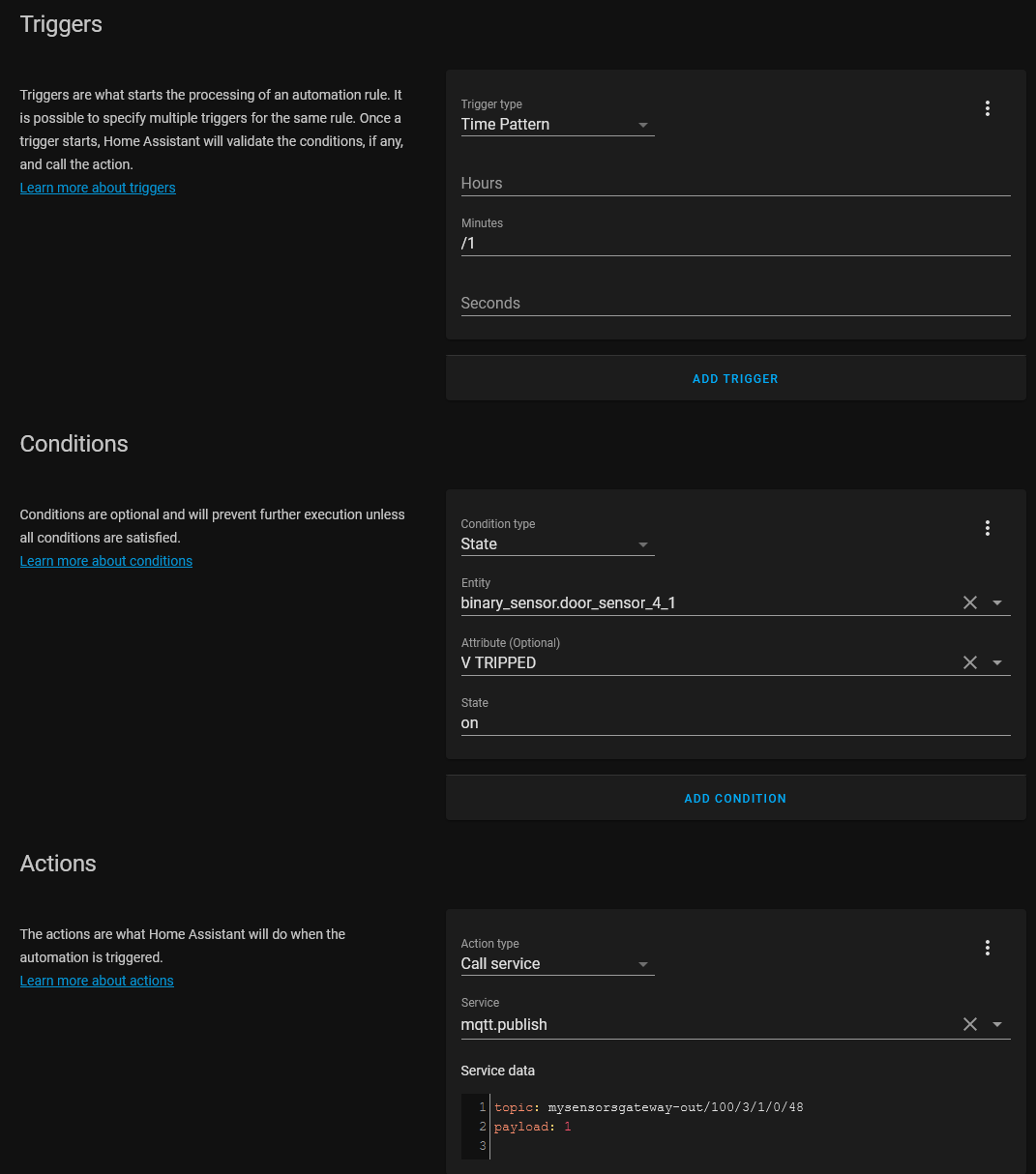
      Checking mechanical locked doors by a battery-based windows/door sensor node
      My Project • • evb  

      9
      7
      Votes
      9
      Posts
      185
      Views

      bjacobse

      Offtopic, but I like your bricks on your house
    • evb

      Best practice for hardware ack and software ack when using a battery node
      General Discussion • • evb  

      10
      0
      Votes
      10
      Posts
      128
      Views

      skywatch

      @mfalkvidd If the message was sent by a cat, maybe......
    • evb

      Testing with a repeater node gives this sometimes in the log file : !TSF:RTE:100 UNKNOWN
      Troubleshooting • • evb  

      4
      0
      Votes
      4
      Posts
      25
      Views

      mfalkvidd

      @evb I dug into the log parser and it contains this: { re: "!TSF:RTE:DST (\\d+) UNKNOWN", d: "Routing for destination <b>$1</b> unknown, sending message to parent" }, so it is already in the log parser, but the regex is wrong. I think it should look like this: { re: "!TSF:RTE:(\\d+) UNKNOWN", d: "Routing for destination <b>$1</b> unknown, sending message to parent" }, With that change, the log parser looks like this for your message: I have created https://github.com/mysensors/MySensors/pull/1462 to fix this.
    • evb

      An LCD node is polling the controller (Home Assistant) to get statuses of other nodes, a HOWTO.
      Development • • evb  

      1
      1
      Votes
      1
      Posts
      38
      Views

      No one has replied

    • evb

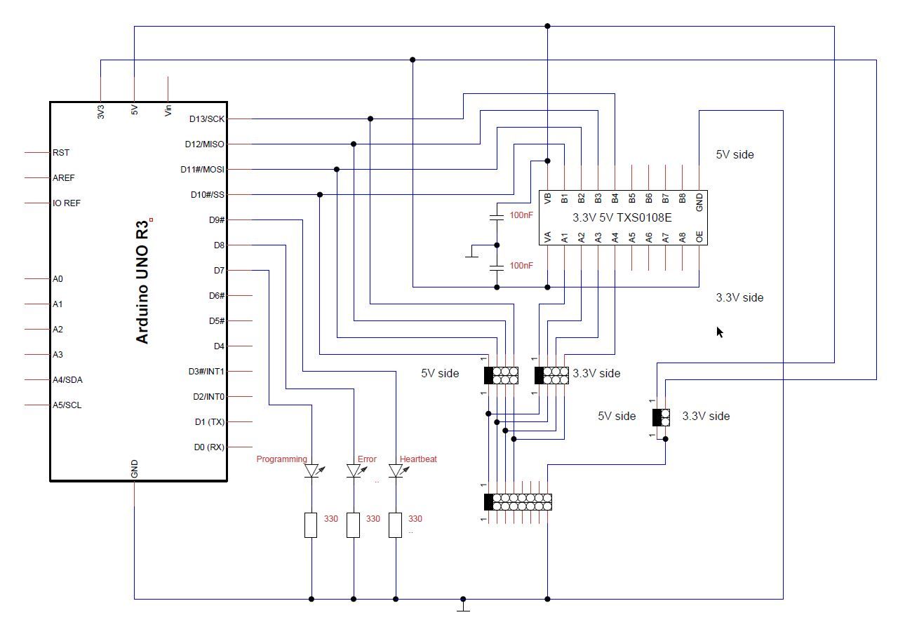
      Using an Arduino Uno as ISP for programming 5V and 3.3V boards without soldering the needed connections
      My Project • • evb  

      3
      2
      Votes
      3
      Posts
      73
      Views

      NeverDie

      Another way is to align the header pins landing pattern in a zig-zag so as to make a temporary solderless connection held in place by the spring tension of the misaligned header pins: I've tried it and it works, but because of the wear on the through-hole plating it's not really appropriate for frequent use. For a once-and-done setup though it seems to work just fine. For instance, Ideally you'd install a wireless bootloader just once and then from then on you don't need a physical connection.
    • evb

      Secure SSL connection between the Arduino MQTT gateway and the MQTT broker server: status?
      General Discussion • • evb  

      2
      0
      Votes
      2
      Posts
      364
      Views

      monte

      Well, I never returned to that topic, because I didn't need it. I think it still isn't implemented, but you have my code from that post, so you can try to modify your copy of Mysensors and it should work. If I remember correctly that was pretty simple modification, new version has probably changed, but not so much I guess.
    • evb

      [SOLVED] Arduino mZero clone RobotDyn SAMD21 M0 board with RFM69HW sending but not receiving parent response
      Troubleshooting • • evb  

      9
      0
      Votes
      9
      Posts
      672
      Views

      evb

      Apparently this day is my lucky day @scalz , you did me think with your comment about the samd21 board not triggering the irq. So I looked up where the pin layouts of all these 'arduino compatible' boards are defined. My used board is a RobotDyn Samd21 M0 board and they claim compatible with a Arduino M0 and I did use the Arduino SAMD boards (32-bits ARM Cortex-M0+) by Arduino version 1.8.3. The code you find at: https://github.com/arduino/ArduinoCore-samd With some help of the google doctor, I did find that the pin layouts are defined in the Variants.cpp file in https://github.com/arduino/ArduinoCore-samd/blob/master/variants/arduino_mzero/variant.cpp (I'm using the Arduino M0 entry when selecting my board) In this file /* * * + Pin number + ZERO Board pin | PIN | Label/Name | Comments (* is for default peripheral in use) * +------------+------------------+--------+-----------------+------------------------------ * | | Digital Low | | | * +------------+------------------+--------+-----------------+------------------------------ * | 0 | 0 -> RX | PA11 | | EIC/EXTINT[11] ADC/AIN[19] PTC/X[3] *SERCOM0/PAD[3] SERCOM2/PAD[3] TCC1/WO[1] TCC0/WO[3] * | 1 | 1 <- TX | PA10 | | EIC/EXTINT[10] ADC/AIN[18] PTC/X[2] *SERCOM0/PAD[2] TCC1/WO[0] TCC0/WO[2] * | 2 | ~2 | PA08 | | EIC/NMI ADC/AIN[16] PTC/X[0] SERCOM0/PAD[0] SERCOM2/PAD[0] *TCC0/WO[0] TCC1/WO[2] * | 3 | ~3 | PA09 | | EIC/EXTINT[9] ADC/AIN[17] PTC/X[1] SERCOM0/PAD[1] SERCOM2/PAD[1] *TCC0/WO[1] TCC1/WO[3] * | 4 | ~4 | PA14 | | EIC/EXTINT[14] SERCOM2/PAD[2] SERCOM4/PAD[2] TC3/WO[0] *TCC0/WO[4] * | 5 | ~5 | PA15 | | EIC/EXTINT[15] SERCOM2/PAD[3] SERCOM4/PAD[3] TC3/WO[1] *TCC0/WO[5] * | 6 | ~6 | PA20 | | EIC/EXTINT[4] PTC/X[8] SERCOM5/PAD[2] SERCOM3/PAD[2] TC7/WO[0] *TCC0/WO[6] * | 7 | ~7 | PA21 | | EIC/EXTINT[5] PTC/X[9] SERCOM5/PAD[3] SERCOM3/PAD[3] TC7/WO[1] *TCC0/WO[7] * +------------+------------------+--------+-----------------+------------------------------ * | | Digital High | | | * +------------+------------------+--------+-----------------+------------------------------ * | 8 | ~8 | PA06 | | EIC/EXTINT[6] PTC/Y[4] ADC/AIN[6] AC/AIN[2] SERCOM0/PAD[2] *TCC1/WO[0] * | 9 | ~9 | PA07 | | EIC/EXTINT[7] PTC/Y[5] DC/AIN[7] AC/AIN[3] SERCOM0/PAD[3] *TCC1/WO[1] * | 10 | ~10 | PA18 | | EIC/EXTINT[2] PTC/X[6] SERCOM1/PAD[2] SERCOM3/PAD[2] *TC3/WO[0] TCC0/WO[2] * | 11 | ~11 | PA16 | | EIC/EXTINT[0] PTC/X[4] SERCOM1/PAD[0] SERCOM3/PAD[0] *TCC2/WO[0] TCC0/WO[6] * | 12 | ~12 | PA19 | | EIC/EXTINT[3] PTC/X[7] SERCOM1/PAD[3] SERCOM3/PAD[3] *TC3/WO[1] TCC0/WO[3] * | 13 | ~13 | PA17 | LED | EIC/EXTINT[1] PTC/X[5] SERCOM1/PAD[1] SERCOM3/PAD[1] *TCC2/WO[1] TCC0/WO[7] * | 14 | GND | | | * | 15 | AREF | PA03 | | *DAC/VREFP PTC/Y[1] * | 16 | SDA | PA22 | | EIC/EXTINT[6] PTC/X[10] *SERCOM3/PAD[0] SERCOM5/PAD[0] TC4/WO[0] TCC0/WO[4] * | 17 | SCL | PA23 | | EIC/EXTINT[7] PTC/X[11] *SERCOM3/PAD[1] SERCOM5/PAD[1] TC4/WO[1] TCC0/WO[5] This is the defined pin mapping for a Arduino mZero. (I was using D2 as IRQ for the RFM69) * | 2 | ~2 | PA08 | But on the pin layout of the RobotDyn board I saw: * | 2 | ~2 | PA14 | On the RobotDyn the pin PA08 is mapped on the D4 arduino pin and not the D2 pin! With the pins D2/D4, RobotDyn is following here the Arduino Zero layout and NOT the Arduino mZero layout! So, I verified the other mappings and found that following pins are different mapped on the Arduino mZero: * | 2 | ~2 | PA08 | * | 4 | ~4 | PA14 | On the RobotDyn Samd21M0 * | 2 | ~2 | PA14 | * | 4 | ~4 | PA08 | So I changed the IRQ (DIO0) from the RF69 to the port D8 (PA06) and bingo it started to work (did choose randomly D8) I saw also a difference in the SPI mapping mZero * | 18 | 1 | PA12 | MISO RobotDyn samd21 m0 * | not defined on their pin layout doc | 1 | PB12 | MISO But it is working, so maybe an error on RobotDyn's documentation? So if I resume the thing: The RobotDyn SAMD21 M0 board is claimed compatible with the Arduino M0 (mZero). In the IDE you must also select the Arduino M0. (selecting Arduino/Genuino Zero xxx will not work) But the RobotDyn used layout is compatible with the Arduino Zero, so pin D2 and D4 are reversed, making the code of the board Arduino M0 not working if you choose to use these pins in your design. So now we can continue to build our gateway, my originally goal. Edit : my MQTT gateway with the RobotDyn Samd21 M0 board, a W5500 ethernet module and a radio RFM69HW is up and running Thanks for all comments that guided me to the solution
    • evb

      Maximum distances between node and gateway with radio RFM69HW chips
      Hardware • • evb  

      4
      0
      Votes
      4
      Posts
      503
      Views

      scalz

      RF performance depends a lot on what's the setup antenna shape (coiled/meandered less efficient, or straigth one), orientation, radiation shape, size, tuning (inside final enclosure might be different, good to check rssis and adjust if needed), quality (lot of bad/untuned on some ebay/Ali shops) GND plane size, software settings the test environment etc for example, here I use 868mhz. I have a compact outdoor RFM69CW node with a simple homemade coiled "wire" antenna (RFM69CW has lower TX power, no power amplifier) sending well at 45-50m from the house, and the RFM69HCW gateway (with power amplifier) is indoor. One thick wall and some trees. Elevation of both ends/antennas is 1.5m, default software settings (for bitrate etc). But in direct line of sight, outdoor, there are also people reporting up to 1-2km range. Compared to MySensors on 2.4ghz, it can be easier to get reliable indoor link with subghz. Like in case you would already have others protocols on 2.4, with wifi and expanders, zigbee, ble, mysensors is not yet resilient to interferences and overlapping freq with these others protocols.. (no frequency hopping for example). It means, 2.4ghz needs more care, and depends on long term evolution of your network..
    • evb

      Security: Signing messages and Encryption of messages: a guide? or more a summary of my tests?
      General Discussion • • evb  

      1
      5
      Votes
      1
      Posts
      650
      Views

      No one has replied

    • evb

      Is there still a breakout board for the Atmel ATSHA204A chip?
      General Discussion • • evb  

      1
      0
      Votes
      1
      Posts
      356
      Views

      No one has replied

    • evb

      [SOLVED] MQTT gateway based on Arduino Uno - Uno compatible W5100 Ethernet shield - RFM69HW radio
      Hardware • • evb  

      7
      1
      Votes
      7
      Posts
      1203
      Views

      ejlane

      Well, it could be that the issue is the voltage regulator on the Arduino board. The higher the input voltage, the more power/heat that needs to be burnt at the voltage regulator. Maybe it's self-limiting because it's getting too hot? The Arduino website lists this part as the voltage regulator: https://www.mouser.com/datasheet/2/146/SPX1117-1889129.pdf On page 6 it claims a thermal resistance to ambient of 46 degrees/W. If you're using 1A and have 12V input then you're dropping 7W across the regulator. This is a temp rise at the junction of 322 degrees over ambient, which it obviously won't do. The datasheet also says that it's internally regulated and will current limit at 155C. Assuming 25C ambient, this only leaves a margin of ~2.8W that can be dropped over the regulator. So you'd have problems with any more than around 400mA. To have a safety margin, I wouldn't plan on more than 300mA or so, or maybe even down more towards 200. This voltage regulator is a nice, low dropout one, so if you could power it from a supply that gave it 6 or 7V instead of the 12 that would give you a ton more thermal margin and the regulator could then allow a lot more current through.
    • evb

      Support for new Arduino Hardware platform: WavGat UNO R3 compatible board
      Development • • evb  

      10
      0
      Votes
      10
      Posts
      4969
      Views

      evb

      @konbaasiang Thanks for the update. I've still the wavgat uno R3 boards somewhere, so I will try it