@monte thanks for your hints. I have actually no peripherals attached during my test. The only external peripheral is a Sensirion sensor (not attched during the power save test) has an auto switch off, but no explicit and it gets down to nano amps.(at least far less than 1uA).
I did a lot of research in the Nordic DevZone but was not successfull. It looks like that the mySensors sleep functions for the nRF52 family does not work as I have expected (I'm using the MyBoardNRF5.h/cpp which includes some kind of Nordic power save features). It might have something doto with the UART switchoff which might not works or ...
I'll also try other nRF52840 moduls to ensure it is not because of one product. I'm using a bare nRF52840 from RFstar which has no LED or any other consumer on it.
https://www.aliexpress.com/item/32921970101.html?spm=a2g0o.productlist.0.0.33f77b08ivGnJC&algo_pvid=834cd241-fead-40dd-a423-762eeaad1e6b&algo_expid=834cd241-fead-40dd-a423-762eeaad1e6b-29&btsid=7de062ad-ecfb-4619-bea6-f9bc99c99996&ws_ab_test=searchweb0_0,searchweb201602_8,searchweb201603_52
Posts made by heinzv
-
RE: Everything nRF52840
-
RE: Everything nRF52840
anybody seen this new Nordic IoT MCU:
https://www.nordicsemi.com/Products/Low-power-short-range-wireless/nRF5340So far only a DK board for 49$ is available. Has BLE 5.1 (incl. long range).
I guess it will take some time till it is supported by Arduiono, Platformio etc.I'm still striggling with the nRF52840 and the low power sleep. So far I'm far away from the 1.5 to 5uA in sleep mode. Maybe someone has a good example for a sleep, internal timer wake-up.
The mysensors project I'm using has 1,5mA in sleep and 15mA during sensor read and send. That is not usable for battery mode. -
RE: Everything nRF52840
@amine-alami what nice schematic diagram are you refering to? I'm looking at this thread very sporadically.
-
RE: stm32 sleep support
@rozpruwacz I have also my "own" nrf52840 mySensors board (50m33mm) which we designed together with ranseyer (made for a few cents). The small nRF5280 modules from RFstar which are on our relatively small mySensors board (which the mySensors 2.6 standard pinheader) cost around 5âŽ. So I consider them as very cost effective.
One of the very interesting MCU's a few of us have tried is the TI CC1352(P) which has 2,4GHz and 868MHz on-board, so you can use one of theme or both together, but there are only a few modules available and they cost almost 30⎠and you need to place them on your own board such as the nRF52840 or any other modules which are meant to solder on own designed boards. -
RE: stm32 sleep support
@rozpruwacz that is clear that you might use other radio's, this is just an added value to use it as it's on-chip and mysensors supports it already. you can just go ahead and combine it with lora/rfm95 (what I also do) and rs485.
But the main question is: Have you found cheap maker boards with such mcu's like STM32L4S5 or STM32L4R5? I have not found anything so far. But I got nrf52840 boards for 5$ and bought 20 pieces at alibaba. AN 1MB flash and 256kB Ram is suffcient for many apps even with tft or epaper display. And you have already Arduino, Platform.io, mysensor, Segger IAR etc. support.
But I dod agree that it would be nice to have a full STM32L4x5 support incl. sleep once maker boards are avaiable. Blue and Blackpill are at least not competitors to nRF52. -
RE: stm32 sleep support
@rozpruwacz why not using one of the nrf52 boards? I was also using stm32 board (bluepill, blackpill, etc.) but at the end, the nrf52 has many advantages over stm32 chips. it is also a 32bit arm mcu, extrem low-power, a lot more ram/flash, a radio on board and it has arduino, platformio and mysensors support. and cheap boards are available.
I'm using nrf52 with e-paper display (utra-low power) and the stm32 ram is not really sufficient. So I don't see any advantage to use stm32 boards over nrf52. -
RE: ðŽ EFEKTA Temp&Hum sensor(ver. nRF52 )+E-Ink display
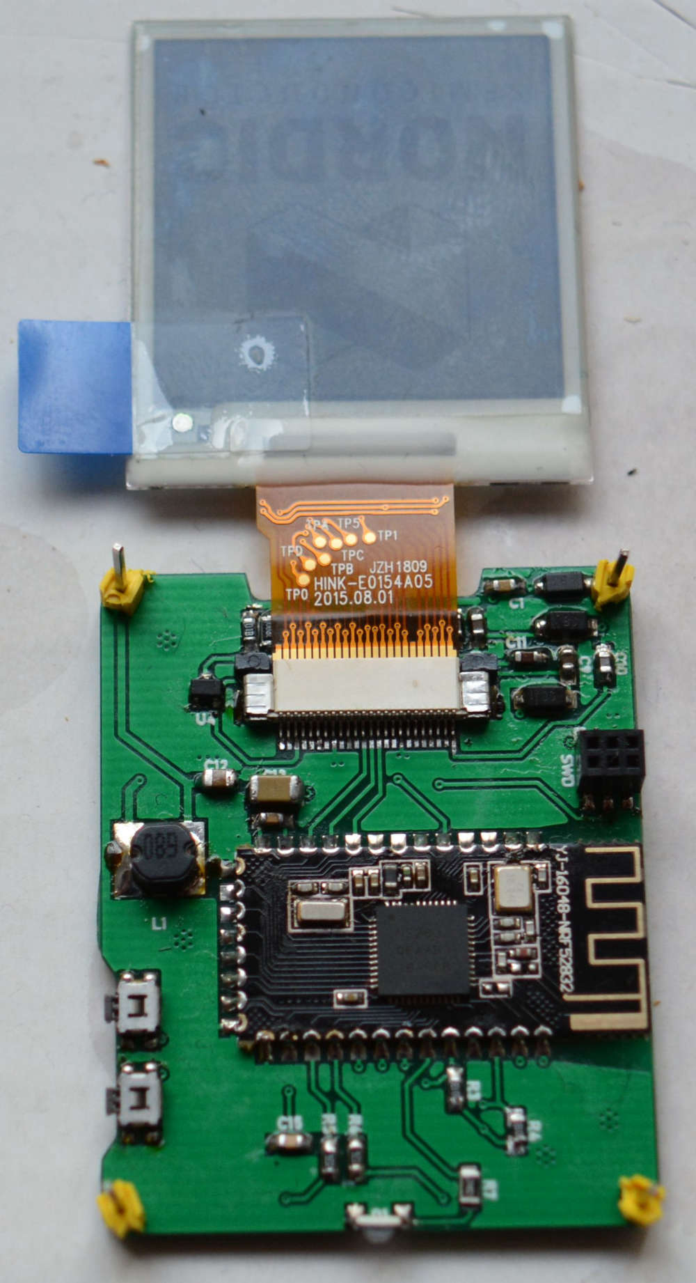
@berkseo took a bit longer and I have now taken a picture with my Nikon Cam, not sure if it helps, I might add another one if required.
But you see the inductor has 68uH. -
RE: ðŽ EFEKTA Temp&Hum sensor(ver. nRF52 )+E-Ink display
@berkseo no I have not solved the problem yet. I 'll take another picture with higher resolution tomorrow and post it here.
The inductance has the value which is specifiied (I think 68uH). I have all ordered by the links provided.
I have checked the soldering and resolved a few times. I think all pins shall be soldered, but I can verify it again. That was also my first thought and checked the ribbon cable over and over again. -
RE: ðŽ EFEKTA Temp&Hum sensor(ver. nRF52 )+E-Ink display
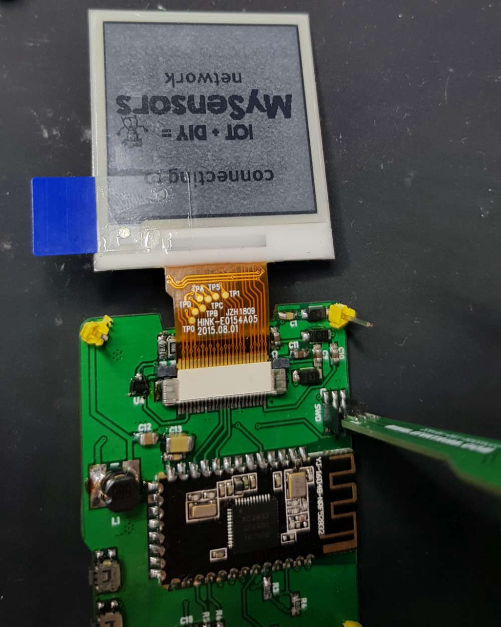
@berkseo I have continued to work on the new PCB's und have oredered some 603 resistors und condensors. I have checked all of the parts and the soldering but did not get the one PCB to displays something. The program runs und I see the LED flashing and also the log looks normal.
A build a second PCB and this one shows the intro graphics but with a grey background and then it stops showing something. No idea what goes wrong.
-
RE: ðŽ EFEKTA Temp&Hum sensor(ver. nRF52 )+E-Ink display
@berkseo Happy new year! I was waiting for an answer from you, so I have not done any further investigation before I have more infos
I have now ordered another batch of 2450 battery holders (I have obviously clicket in the second link in your parts list which was the 2477).So based on your info, my C13 is definitly wrong, I have used a 0.1uF and need to change it to a 100uf (what are you using as you write 47uF to 200uF ?). I think I need to order them first. For C12 I used a 10uF so that fits.
I think I could also have some problems with the 0.1uF parts as I have only the larger 1206 which I have to replace with 805 or 603 sized. I have ordered them already but you know that takes another 4-6weeks. So I'll wait till all parts are there and continue then with your infos and the correct ordered parts.
I have also problems with my new script as my power consumption was first 0.8mA (800uA) and now it's even 3.1mA during sleep (on my other PCB's), but was following your sleep procedure (putting all internal and external devices to powerdown). I was expecting somewhat between 2 and 20uA, so I have to analyze what is wrong.
So you solder your PCB in 0.5hour? Then I might order the PCB's bette rfrom you It takes me at least 2+ hours (the first was 3hrs).
I have a super small soldering iron and I also have a hot air SMD soldering station and quality solder paste. May I try it again with solder paste.more then later.
thanks and bye till later
Heinz -
RE: ESP32 based IoT gateway/control hub with TFT, touch, RFM69 and more..
@martin-harizanov said in ESP32 based IoT gateway/control hub with TFT, touch, RFM69 and more..:
RFM69HW
oh, that is bad luck. I had one RFM69 in mind (I think the HCW) which is pin compatible with the RFM95. Ranseyer made one PCB which can take a RFM69 or RFM95 at the same place (just in case somebody still want to use the RFM69).
Then I can't order it. However, a great project. -
RE: ESP32 based IoT gateway/control hub with TFT, touch, RFM69 and more..
@Martin-Harizanov Great job Martin! I like and use the ESP32 since it was introduced.
If I would order the TFT32 without the RFM69HW (39âŽ) and would replace it with my RFM95 (LoRa) modules.
The RFM69HW (only the HW version) and the RFM95 have the same pinouts right? Can you confirm that? I only use RFM95, no RFM69. -
RE: ðŽ EFEKTA Temp&Hum sensor(ver. nRF52 )+E-Ink display
@berkseo I've got your Temp/Hum sensor today and the PCB's (3+3). Since I have ordered the cr2477 batteries and your batterholder takes only the cr2450, I've tried it with the program adapter and USB power. It works. Thanks. I have ordered now additional cr2450 batteries.
I took the batteryholder form your list and they are for the cr2477!Then I soldered my own first two PCB's, the battery PCB and the Sensor PCB. It took me quite a while (3 hours at least). It's nothing for beginners (but I not a beginner )
However during my testing, I found my battery PCB working and the sensor node runs the MYSensors part and the LED blinks but the E-Paper does not work and also the SHT20 returns 998 for temp and hum.I have not found the C12 capacitor in your parts decription list, but only a C14 (which is not printed on the PCB) with 10uF. So I assumed the C12 = 10uF. I have seached the page and there is no C12.
One the other hand, I have not found C14 on the new PCB. Maybe it's below C13 and no part print on PCB? The C13 is larger then the pads below, so it's confusing.
Maybe you can update/correct it on openhwardware, so that I can solder it correct.So looking for the problems with e-paper and SHT20: A schematic diagram would really really help me, otherwise I'm lost. Please provide it (or at least via a PM?).
Would it be possible to get it? If you have e.g. an Eagle project (schematics and board).It was really essential, that you provided the programm adapter for the tiny SWD connector. Thanks for that!
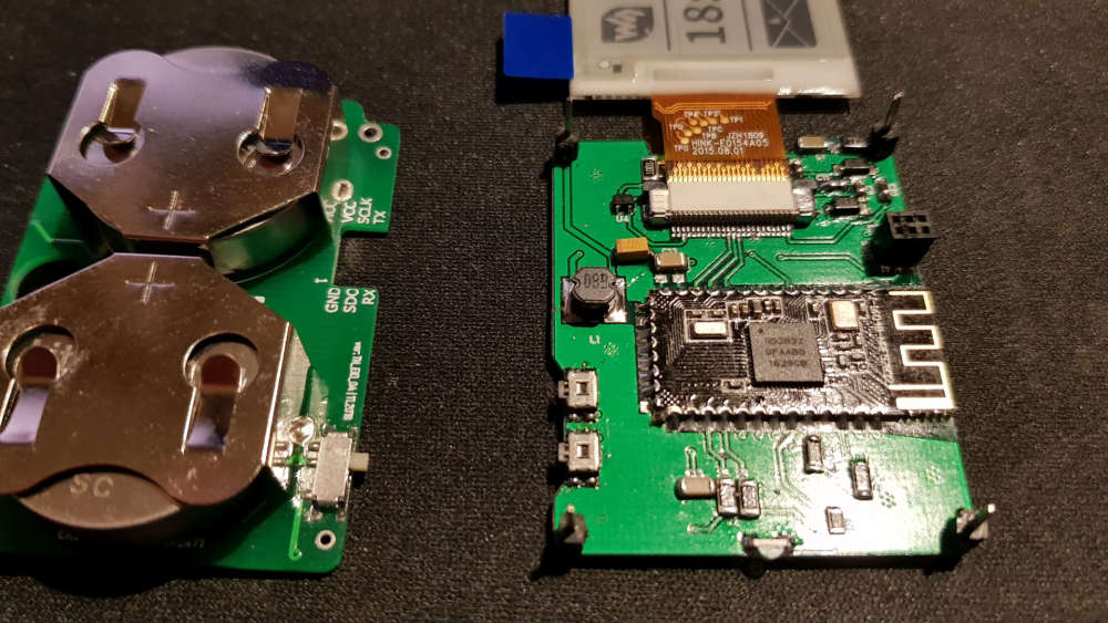
here are my soldered PCB's:
-
RE: Everything nRF52840
@NeverDie You doing a great research! I have quickly checked your REPL code and the radio lib.
So you have implemented a OSI Layer 3+4 (Transport Layer with IP/TCP Stack).
I'm wondering if/how this can be used to complay to BLE 5.0 (long range), ZigBee and Threads which the new Nordic SDK (Zigbee and Threads 2.0) offers? Are they also using the Softdevice S140 (6.1) libs or ...?
There is a ZigBee OTA update example provided by Nordic (but I have not yet enogh time to test it).
Currently, I'm still using MySensors and the NRF5_ESP (Nordic private) protocol which works. IT would be also interesting to use a more industry standard protocol like ZigBee or THREADS which seem to be also supported by OpenHAB.
I'll certainly do further investigations in this direction. I have tried to test it with Segger Embedded studio and also with IAR Studio for ARM (the second requires some newer 32Bit version libs from Nordic and an internat request for that was raised already). Segger works fine with the J-Link adapters. -
RE: ðŽ EFEKTA Temp&Hum sensor(ver. nRF52 )+E-Ink display
@berkseo looks very good, very professional work. I'll solder a few devices once I get the new PCB's and will also work further on my version of the firmware. It works already quite nice (transfering float values and showing decimals).
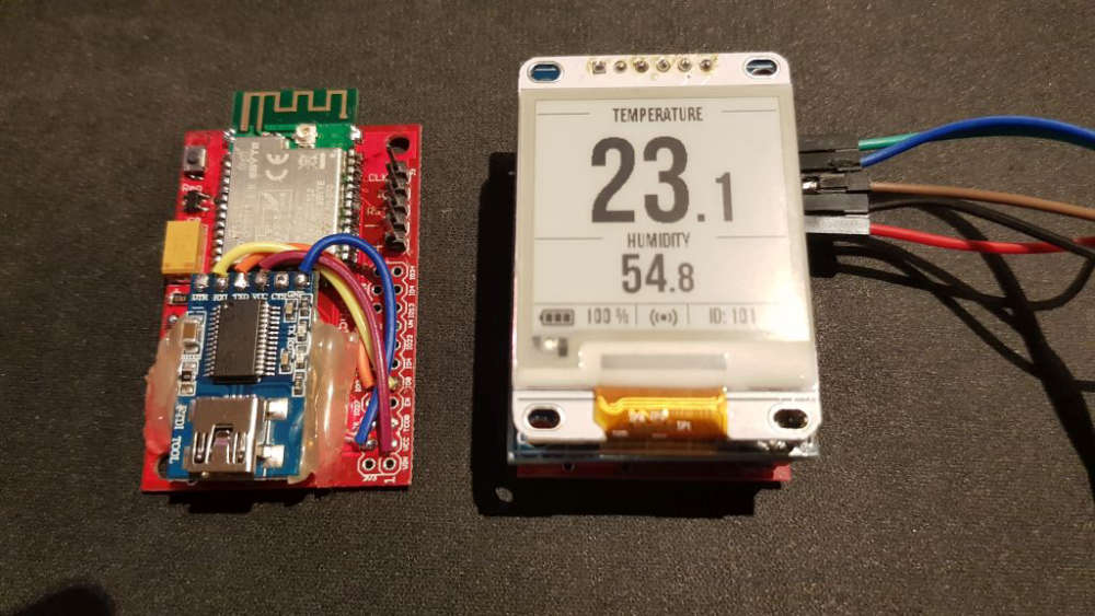
Attached the picture of a working pair of a sensor node (using my PCB's) and a SHT31 and a nRF52 serial gateway. -
RE: Everything nRF52840
@neverdie interesting research and ideas. Have you tried to get BLE 5.0 running (the S140 SD) or using the nrf52840 radio features (best with long range) so that we can consider a sensor node/actor and does the sleep properly work? There are some basic features which have to work before switching the development/runtime env.
-
RE: ðŽ EFEKTA Temp&Hum sensor(ver. nRF52 )+E-Ink display
@berkseo good to hear. And you also mentioned to send some new PCB'
s? Let me know if I had to pay something additional. -
RE: ðŽ EFEKTA Temp&Hum sensor(ver. nRF52 )+E-Ink display
@berkseo glad to hear, that it worked.
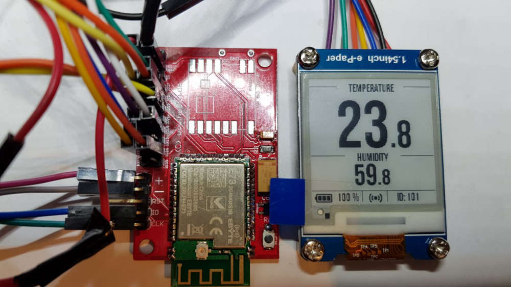
I'm meanwhile working on the sketch for the Tem & Hum sensor node. As written, I've switched to the GxEPD e-Paper library. It is easier to use and is installable via the Arduino Studio or via platform.io.
I've evaluated a lot of fonts and have finally found one I like and which fits to the display even with the decimals. I used the fontconvert from the GxEPD lib which can convert any TTF or OTF font.
Here is a picture (I'm still using the MySesnors PCB from ranseyer waiting for the new PCB's from you)
-
RE: ðŽ EFEKTA Temp&Hum sensor(ver. nRF52 )+E-Ink display
@berkseo Thanks, very good modifications. I'll wait patiently I'll then not use the 5 + 5 PC's and eait for the new ones.
Do I understand you right, that I'll receive another 5 + 5 updated PCB's without additional money charged? That would be great (if required I can send you additional âŽ's or US$).
Thanks for the font-hints. I'll test it once I'm back from my BIZ-trip. -
RE: ðŽ EFEKTA Temp&Hum sensor(ver. nRF52 )+E-Ink display
@berkseo I have updated my post above with an additiona picture.
You can do all on Windows (I mostly use Windows 10 x64). I sometimes use Linux like for creating the BMP clones. I'm using the latest Mint version in a VMware VM.
Let me know if you need more infos ...BTW: I was further working on the own created nRF52832 PCB's with ePaper (I have many E73 modules left) and will start soldering the PCB's I have ordered from you if all parts are there (most of thema are).
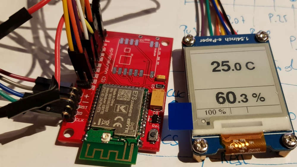
The one ordered soldered module is still in transit (or I did not get it so far).Below another picture of the ePaper output. I have tested the idea with two fonts: The larger one for the non decimals and a smaller one for the decimal. I'm using the GxEPD standard e-Paper library in my latested sketch, as it's easier to use, has more fonts und is ready for more ePaper modules/sizes.
It is just an intermediate state (batter symbol, larger font missing etc.). -
RE: ðŽ EFEKTA Temp&Hum sensor(ver. nRF52 )+E-Ink display
@berkseo you have to connect your E73 module with a J-Link adapter, if the adapter is recognized by nRFgo Studio, the nRFx Programming will be enabled (turn from grey to black) and then you can select "Recover" (only shown if you have a locked device). You should do then also a "Erase all").
Again, it only works with a Segger compatible J-Link adapter. Do you have one? It is anyhow recommended if you want to use Segger Embedded Studio (required for using the nRF52840 and the newest 15.2 SDK).
The other/second method could work with a ST-Link or black magic probe (a 2⎠clone can do it, I created a couple of them) and with openocd.The unlock screen look like this, if you have a locked or no device connected but a valied J-Link adapter
And after recover, you get a screen like this to erase or flash a program
-
RE: ðŽ EFEKTA Temp&Hum sensor(ver. nRF52 )+E-Ink display
@berkseo (update): What kind of probems did you face? Why have you been unable to run this modules in the Arduino? Did you have problmes to upload the sketch?
Maybe you had the problem, that the modules are not detected during upload!
I had the same problem and the EBYTE E73 nRF52832 modules are locked by factory and thus not detected by the IDE's. You can unloack them with nRF Go studio, nrfutil (or nrfprog) and do a mass erase. In nRF Go studio you might require a J-Link programmer, you can olaso unlock it with openocd with a simple cheap ST-Link adapter.
openocd -s $OPENOCD/tcl -f interface/stlink-v2.cfg -f target/nrf52.cfg -c init -c "reset init" -c halt -c "nrf52 mass_erase" -c "program $FIRMWARE verify" -c reset -c exitI typically use the nRF52 modules with my selfmade Black Magic Probe (1.60), which is supported by Arduino IDE.
The EBYE modules have all the Nordic reference design parts soldered. So nothing else is required (no coils etc.)Here are my two modules which work:
I found this breakout boards for the E73 module here
https://oshpark.com/shared_projects/q4weF4UL
The other module were designed by ranseyer and myselflet me know if you have more questions
-
RE: ðŽ EFEKTA Temp&Hum sensor(ver. nRF52 )+E-Ink display
@berkseo I found out, that I still miss two parts (from AE), everything else is there. So I started a testing with my development boards.
I attach a picture of this setup. I use a CBYTE nRF52832 module, a SHT35 (SHT20 is not there and the 1uF capacitors for the bare e-paper displays) and a waveshare e-paper with PCB.
I'm now out for two weeks and will then have my parts hopefully.
The module on the right side is my BMP (black magic probe). -
RE: ðŽ EFEKTA Temp&Hum sensor(ver. nRF52 )+E-Ink display
@berkseo thanks, that version works!
Maybe you can consider the one decimal digit for the temp (21,6 C). Otherwise I'll do some investigations.
The font90 will be too large (maybe font72) or we need a smaller font and the decimal digit can be a smaller font (mix of two fonts for temp e.g. font72 and font48).
Have you found a utility to convert fonts (e.g. TTF from Windwos) to generate matching font's for e-Paper (I have not yet found someting).
Since we have now enough RAM, have you thought about using the e-paper standard lib GxEPD? That has a least better font support (and also partial update)? -
RE: ðŽ EFEKTA Temp&Hum sensor(ver. nRF52 )+E-Ink display
@berkseo thanks a lot for the demo code. With some small correction I got it working (give some compile errors).
Could you please check if the font90.c is missing (which is used in the code but not found).
And there seem to be a typo (?) in the font36 (gives an error). I changed from Font24_Table to Font36_Table.
sFONT Font36 = {
Font24_Table,
41, /* Width /
46, / Height */
}; -
RE: Everything nRF52840
@neverdie sure, I did not epect Rome to be built in one day by one person I was just curiuos in which direction you're heading.
If the OTA feature is one of the key features, I was thinking of using a couple of information provided by Nordic such as as details on the OTA/flashing process of the nRF52 as well as the OTA DFU bootloader example provided as part of the 15.2 SDK.OTA/Flash process
https://infocenter.nordicsemi.com/index.jsp?topic=%2Fcom.nordic.infocenter.sdk52.v0.9.0%2Fbledfu_architecture.html
http://infocenter.nordicsemi.com/index.jsp?topic=%2Fcom.nordic.infocenter.tools%2Fdita%2Ftools%2FnRF_Connect%2FnRF_Connect_DFU.htmlOTA/Flash sources in C/C++
Just a few thoughts (I have to investiage) if we could use the sequence from the bootloader examples and they used libs for receiving data/code and initialized the flash process using the provided libraries
nRF5_SDK_15.2.0\components\libraries\bootloader
here I see in the dfu sub-dir the required function to observer, receiver and flash codeThere a multiple examples how the code is transfered: via USB/serial, BLE/Zigbee, ANT ... and I guess we could use also the nRF24 protocol. Also encryption functions are available in the samples (secure dfu bootloader).
We need to derive, what nee to be done on the sender side to start to set the target to dfu mode and initiate the code transfer. Maybe that is also a tricky task.
Do you see that this approach can work and could be added to own C/C++ sketches and thus also added the MySensors project (of coure we need to include and use the required nRF52 libs for dfu)?
-
RE: Everything nRF52840
@neverdie You are a hero Now the question is of course what comes next? Do you see any chance to get some of the findings implemented into the MySensors project? or will it be a completly new nRF52840 thread/story? Like using ZigBee or BLE 5.0 long range (remember the discussion we had with @scalz if it makes sense to use MySensors aor use a full standard stack like ZigBee or BLE 5.0).
What are your thoughts and plans? Best option to build sensor nodes/actors with nRF52840? -
RE: ðŽ EFEKTA Temp&Hum sensor(ver. nRF52 )+E-Ink display
@berkseo I have now the PCB's and my parts. Ihave now a few questions
1.) When can we expect the sketch code?
2.) Can we also have the schematics?
3.) How to you solder parts like the TPS62745DSSR? Are you using a reflow oven? or hot air or even a small solder iron? -
RE: Everything nRF52840
@wormhole I took a quick look at this HomeSmartMesh project and it's certainly interesting.
However, the MySensors project is more mature, has a large community, supports more MCU's and sensors and many HW projects are using/supporting it. It also supports nRF51 and nRF52 MCU's already to a certain extent (I guess using the internal nRF24 radio protocol and external RF chips like RFM69/95).
Beside that, it supports also a couple of home automations suite like FEHM, OpenHAB etc.
I'm currently on OpenHAB 2.3 using the MySensors Gateway for OpenHAB.
I think it would be rather a good idea, that we get the new nRF52840 features and RF protocols supported by MySensors (such as the BLE 5.0 with the long range feature).
We had already the discussions on IEEE 802.15.4 / Thread / Zigbee which are also great for home automation. The question was also, if we can/should include it in MySensors or are these competing technology stacks to MySensors.
I personally like the MySensors project, because it project a good development infrastructure with a lot of supported/preconfigures sensors which makes it quite easy to creates sensor nodes..
Now we are exploring how to best integrate and use the nRF52840 boards. NeverDie seem to be quite ahead of us and exploring also micropython option (not sure how far that fits into the MySensors concept -
RE: ðŽ EFEKTA Temp&Hum sensor(ver. nRF52 )+E-Ink display
@berkseo Yes, I'd like to change the SW so that the temp shows also one decimal like 21,6 C
For the decimal a smaller font likes quite nice such as shown in the picture of the sensor from Xiaomi.
I don't have a specical font in mind but rather recommend to take proportional font rather than a mono-space font whcih is rather used for debugger output but not for a productive end user display. The space between the digits is typically smaller/less using a proportional font and looks more elegant than using mono-font.I know, that the 10 PCB's are 5 + 5 (5 sets).
I can imagine, that selling soldered PCB's is not a very interesting business and is boring and time consuming for just little amount of money. I was buying one just as reference and will solder the other 5 sets by myself. I know how much effort that is. -
RE: ðŽ EFEKTA Temp&Hum sensor(ver. nRF52 )+E-Ink display
@berkseo I have ordered already the 10x PCB's and also most of the BOM. I'm also going to order one full mounted PCB (if still available).
Can you do me a favour: I need one decimal digit for the temp (not required for hum) but certainly for the temp!
Here is a hint/proposal: You can make the decimal digit smaller. I attach one sample from a Xiaomi device (unfortunatly has no wireless and not sure if/how it can be hacked and wireless added). -
RE: Everything nRF52840
@redferne I was trying to get your platform and board extention as wellas the BLE library added to platformio, but got stuck afetr many many hours and many attempts (too much to add all the problems in one post). I'm using platformio with Windows 10 (I guess you use it with Linux/Ubuntu and also with a couple of command line tools)
I was trying to install this two:
https://github.com/Redferne/arduino-nRF5
Redferne/arduino-BLEPeripheralI was trying to build a couple of simple examples and also the
C:\users\internet.platformio\lib\BLEPeripheral\src\BLEBondStore.cpp:11:12: fatal error: nrf_soc.h: No such file or directory
and
C:\users\internet.platformio\lib\BLEPeripheral\src/BLEPeripheral.h:136:5: error: 'nRF52840' does not name a type; did you mean 'NRF52840'?and all other following errors are probably the result of the above ones.
Any hints?
Another question: How to define/declare the usage of the S140 softdevice in the project?
Using the PlatformIO IDE, not the command line. -
RE: Everything nRF52840
@redferne wow and thanks again for your fast and complte/detailed answer.
I like especially- that you already started to use/support softdevices S140 and thus BLE 5.0, thread and Zigbee is "potentially" available
- that you also succesfully use Black Magic Probe, as I also wante to use it because it works in Arduino IDE and Platform.io and it supports also an UART Port to communicate (I also use Blue/Blackpill BMP's)
It would be great if it would be posssible (if not already) to use BLE 5.0 with the long range feature (that is not supported by the older S132 or nRF52832). Zigbee would be also great. But not sure what of the features (for a reliable longer indoor range) would be usable from within the MySensors project (beside using the nRF52 as/with the nRF24 proticol).
-
RE: ðŽ EFEKTA Temp&Hum sensor(ver. nRF52 )+E-Ink display
Once the code is available I would order 10x PCB's.
Also, do you have a link to the nRF52832 module? (a 840 version would be also very nice :-))ok, I just odered the 5 PCB Sets.
Beside the link to the nRF52832 Module, please provide also the link to the e-Paper Module. -
RE: Everything nRF52840
@redferne thanks for your effort spent to support nRF52840 for VS Code/Platform.io. I'll certaily give it a try. The good thing with platform.io is that it's easier to use/import existing arduino (ino) projects than in e.g. Segger Studio which only supports licensed J-Link flash/debug adapters.
Two questions:
1.) Does your "port" support also the 15.2 SDK features of the 840 (Softdevice S140, BLE 5.0 long range, ZigBee, Thread ...)
2.) What flash method is supprted/used or you're using? Just plug the USB dongle in and it can be uploaded?Oh, a third question: If I use bare nrf840 Modules, what flash adapter/mode would you recommend or have you tested (I have the 840 DK board, a ST-Link v2 and a Balc Magic Probe adapter)?
-
RE: Everything nRF52840
@NeverDie thanks, appreciate your help as you are far ahead.
Here is my update: I have build 4 nRF52832 boards with the E73 EBYTE modules and two nRF52840 board with the tiny holyiot modules (see picts below).
It seems that by using the wiring shown in my last post, I can flash the 840 boards. I'll also try again one of the working 832 boards later (I'm in business trip the next few days).
But I have a couple of questions to you:
1.) I don't know how to identify which MCU will be flashed. I only see the J-Link adapter in Segger or the board with the Segger Serial in nRFgo Studio. How can I know, that I'm not flashing the DK onboard MCU? Where is this shown, indicated where the flashing will go? That is strange to me. Another example is my sel build Black Magic Probe: It shows which devices are connected to it and you can select one (if multiple are shown in a select - select target 1,2 ...)
2.) How can I make use of any bootloader (DFU, Serial, USB, OTA, ANT etc.) so that flashing with the DK is not always required? I have not found a good way so far to flash any useful bootloader (I have tried some of the examples). The onyl one which creates a serial devices is the example for the PCA100059 (the USB dongle) which shows a serial device: nRF52 SDFU USB (COM75). HOw to make use of that (I have tried all of the offered programmer als oin Arduino IDE but could not upload/flash my blink sketch)
3.) How to you flash the USB dongle beside using the nRFconnect which requires the compiled image?
Are you also soldering the SWD pins and use them with the Segger and the DK?
4.) When I flashed your micropython (or circuitpython?) for the 840 (my board). How to I connect and use it? My 840 boards have it's own USB port (see topic 2, which shows the nRF52 SDFU port when I flash the one bootloader). When I flash the MP, the ports are gone (how to connect via USB, Serial, Terminal etc.)?I've also tried a couple of other things like a DFU bootloader with a S140 softdevice (as it was recommended by Nordic) but was not sucessful to combine them (the S140 was flashed, but then?)
I have many more questions but I hope we can sort out some of the 1-4. I hope I have described them so that you can follow my thoughts and questions
nrf52840 on DK
nRF52832 on BMP
-
RE: Everything nRF52840
@neverdie I admit that I also powered the module via the DK because it takes less than 20mA. I used this connection description:
But I'll try to use a complete an external PS next time and see if it makes a difference. -
RE: Everything nRF52840
@NeverDie thanks for the hints/offer:
I have connected to the nRF52840 DK via the P20 connector
Here is the wiring setupVDD---> VTG of P20 in DK board
SWDIO--> SWDIO of external board
SWDCLK-->SWDCLK of external Baord
GND DETECT--> GND of external Board
GND--> GND of external baord. -
RE: Everything nRF52840
@NeverDie great job! I'll definity try it on my holyiot bare modules, but I'm still fighting with the flashing via either the Nordic DK and/or ST-Link v2SO far I was not successfull (I only got it to run with Arduino IDE and BMP, but that is not usable in that case). DK seem not recognize my external nRF52840 and the ST-Link wants some address ranges so I'm trying to get it run with openocd, but that also returns errors. So I'm stuck and wasting many evenings/nights (with Google).
-
RE: Everything nRF52840
My nRF52832 moduls with MySensors in nRF24 mode seem to work, I have to start another node acting als Gateway and see if they communicate and what distance can be reached in the nRF24 mode.
| / |_ / | ___ _ __ ___ ___ _ __ ___
| |/| | | | _ \ / _ \_ \/ __|/ _ \|
_/ __|
| | | | || || | / | | _ \ _ | | _
|| ||_, |/ ___|| ||/_/|| |/
|__/ 2.3.1-beta24 MCO:BGN:INIT NODE,CP=RNNNN---,VER=2.3.1-beta
28 TSM:INIT
30 TSF:WUR:MS=0
31 TSM:INIT:TSP OK
33 TSM:FPAR
40 TSF:MSG:SEND,255-255-255-255,s=255,c=3,t=7,pt=0,l=0,sg=0,ft=0,st=OK:
2048 !TSM:FPAR:NO REPLY
2050 TSM:FPAR
2057 TSF:MSG:SEND,255-255-255-255,s=255,c=3,t=7,pt=0,l=0,sg=0,ft=0,st=OK:
4064 !TSM:FPAR:NO REPLY
4066 TSM:FPAR
4073 TSF:MSG:SEND,255-255-255-255,s=255,c=3,t=7,pt=0,l=0,sg=0,ft=0,st=OK:
6081 !TSM:FPAR:NO REPLY
6083 TSM:FPAR
6090 TSF:MSG:SEND,255-255-255-255,s=255,c=3,t=7,pt=0,l=0,sg=0,ft=0,st=OK:
8098 !TSM:FPAR:FAIL
8099 TSM:FAIL:CNT=1
8101 TSM:FAIL:DIS
8103 TSF:TDI:TPD
18105 TSM:FAIL:RE-INIT
18107 TSM:INIT
18108 TSM:INIT:TSP OK
18110 TSM:FPAR
18117 TSF:MSG:SEND,255-255-255-255,s=255,c=3,t=7,pt=0,l=0,sg=0,ft=0,st=OK:
20125 !TSM:FPAR:NO REPLY
20127 TSM:FPAR
20134 TSF:MSG:SEND,255-255-255-255,s=255,c=3,t=7,pt=0,l=0,sg=0,ft=0,st=OK:
22142 !TSM:FPAR:NO REPLY
22144 TSM:FPAR
22151 TSF:MSG:SEND,255-255-255-255,s=255,c=3,t=7,pt=0,l=0,sg=0,ft=0,st=OK:
24159 !TSM:FPAR:NO REPLY
24161 TSM:FPAR
24168 TSF:MSG:SEND,255-255-255-255,s=255,c=3,t=7,pt=0,l=0,sg=0,ft=0,st=OK:
26176 !TSM:FPAR:FAIL
26177 TSM:FAIL:CNT=2
26179 TSM:FAIL:DIS
26181 TSF:TDI:TPD -
RE: Everything nRF52840
@nagelc So everything works now with the BMP using the MyBoardNRF5. At least it supports the nRF52832 (if I'm lucky also the nRF52840) but I started with my barebone 832 modules.
So it upload the sketch and it does also reset and start.
I could also do the connection to the second serial port now with Terra Term and get the Serial.println. Cool.
The secret was, that I created another BMP for my blackpills (I did a couple of tweaks) and connect now the HW serial of the nRF52 to the BMP serial (UART2) and it forwards it via the USB of the BMP to the COM port.The output looks now like yours when I do an upload:
WARNING: Spurious .ci folder in 'MySensors' library
WARNING: Spurious .mystools folder in 'MySensors' library
Build options changed, rebuilding all
Sketch uses 3720 bytes (0%) of program storage space. Maximum is 524288 bytes.
Remote debugging using \.\COM58
Target voltage: unknown
Available Targets:
No. Att Driver
1 Nordic nRF52
2 Nordic nRF52 Access Port
Attaching to Remote target
0x00000ae0 in ?? ()
Reading symbols from nRF52832_Blink.ino.elf...done.
Loading section .text, size 0xe88 lma 0x0
Loading section .ARM.exidx, size 0x8 lma 0xe88
Loading section .data, size 0x74 lma 0xe90
Start address 0x5f8, load size 3844
Transfer rate: 27 KB/sec, 640 bytes/write.
Temporary breakpoint 1 at 0xbc4: file D:\mcdev\arduino\portable\packages\sandeepmistry\hardware\nRF5\0.6.0\cores\nRF5\main.cpp, line 28.
Starting program: C:\Users\internet\AppData\Local\Temp\arduino_build_913185\nRF52832_Blink.ino.elf
Note: automatically using hardware breakpoints for read-only addresses.Temporary breakpoint 1, main ()
at D:\mcdev\arduino\portable\packages\sandeepmistry\hardware\nRF5\0.6.0\cores\nRF5\main.cpp:28
28 {Program complete!
Here is the picture of my BMP and the nRF module:
-
RE: Everything nRF52840
@nagelc I have tested both w/ and w/o softdevice, it doesnt make a difference but yes I'll remove it again.
My boards (the E73 module) have an external 32kHz crystal osci for RTC.
In Arduino, you can only select one port. If COM58 is set (for the programmer) then it would open the serial monitor also on that port. However I have tried to use port 51 with another terminal (putty) and it does not connect (I've tried with different baud rates).
I'm not sure but I think (and read) that the second port is only for the SW update of the BMP and not for debugging. Debugging is most likely also on port 58 but for the GDB and not for Arduino, but if it is used (initiated) via Arduino, I could not connect to GDB with a command terminal, so I think the programm has to be started with the command windows and GDB. I've also tested that from that direction and was also not succesfull (I spnt many hours with Google and BMP docu and GDB).
I also don't know how to use the non COM (USB only) devices like the "Trace Capture" as thery are not visible/offered in Arduiono IDE.You're using BMP with Arduino IDE? How are you doing the serial output?
How can you used two different ports in Arduino (there is only one port setting)? -
RE: Everything nRF52840
@neverdie good discussion, but in order to get my desired solution which is sensor nodes with E-Paper and working with OpenHAB I need I either get the nRF52 modules running with mySensors (ideally just using the Arduino porject and IDE) using the nRF option (I think there is some initial nRF5 support) and using the older nRF24 protocol, or using LoRa with an RFM95 module (which is also supported) or I switch completly to Segger and make a ZigBee V3.0 solution (requiring a ZigBee gateway for OpenHAB). With my new Philips Hue HW version and the new SW firmware upgrade. It is claiming to support ZigBee V3.0 devices which includes also Temp/Hum sensors.
I'm also looking forward for the solution from berkseo where he does exactly that with and nRF52, but that seem to take some time to make it available.
https://www.openhardware.io/view/629/Temperature-and-humidity-sensorverNRF52832E-Ink-display#tabs-instructions -
RE: Everything nRF52840
@nagelc Thanks for your response and trying to get me further.
I'm trying to get you as much infos as possible:
I made a couple of screenshots and picture of my environment. Maybe that helps to trace down to the problem.
I followed exactly the instructions from sanseeps Arduino/nRF5 configuration/installation.
Uploading the bkink example with the ST-Link V2 works, but there is no serial print, no debug, thus I'm trying the BMP way.Here some setttings from my Arduino IDE (Tools section)
Here are my different BMP modules I have used
and the COM devices in Win 10
I have tried all kind of driver (using Zadik 2.4), but WInUSB, lisbusbK, libusb ... they all create USB devices only but no COM devices, which Arduino IDE does not "like") only the usbser driver gives me COM devicesand the target device I'm using (which works, when I load the sketch with the ST-Link and select ST-Link in Arduino IDE)
-
RE: Everything nRF52840
@neverdie To my first statement: I was just wondering why I can upload sketches with teh ST-Link V2 dongle (but no serial output/debug windows) but the BMP might face read-only protection (I thin kthe upload script should have some kind of mass erase before upload)?
Regarding my question: I think I you understood my question right and I also read the nRF DK features and it says it features a SEGGER J-Link OB Debugger with debug out functionality. So I guess it's a flasher/debugger not only for it's on-board nRF52840 MCU but also for external nRF modules connected to the DK right?Are you're also using the DK with the Arduino IDE (though with restrictions like no full nRF52840 support) and the mySensors project?
Meanwhile I'm exploring the nRF52840 USB dongles. And maybe I'll get along with the BMP modules and understand how the work with the Arduino IDE (so far I spent many hours with Google und no success).
-
RE: Everything nRF52840
@neverdie I can do upload with the standard ST-Link V2 Dongle on the same bare E73 module but for the BMP it is read-only?
How do you flash the bare modules (not the DK)? -
RE: Everything nRF52840
@neverdie and @Nca78 thanks for the quick response, I have ordered the nRF52840 DK from Nordic (via Mouser). That works with Segger and also with Arduino Studio too (for the simple and existing 52832 projects like mySensors)?
And fo the Arduino Studio (or VS Code) is there a serial terminal for debug output too?
How to you flash then the bare nRF52 modules which have only the SWD interface (I have plenty of them)?@nagelc I have again tried my Black Magic Probe Dongle with Arduino IDE, but it does not yet work for me (maybe I still have not understood it). In Arduino Studio I have tge GDB serial port but neither the upload works properly nor I have understood how to use it with the GDB debug window.
I attach the devices (Windows 10) and the output from Arduino IDE. Maybe you can give me further hints:
I used a simple blink sketch which works with ST-LInk V2 upload but not with BMP. Here is the output from the upload:
Sketch uses 3600 bytes (0%) of program storage space. Maximum is 409600 bytes.
Target voltage: unknown
Remote debugging using \.\COM58
Available Targets:
No. Att Driver
1 Nordic nRF52
2 Nordic nRF52 Access Port
Attaching to Remote target
0x00000ad0 in ?? ()
Reading symbols from nRF52832_Blink.ino.elf...done.
Loading section .text, size 0xe10 lma 0x1c000
Loading section .ARM.exidx, size 0x8 lma 0x1ce10
Loading section .data, size 0x74 lma 0x1ce18
Start address 0x1c5fc, load size 3724
Transfer rate: 26 KB/sec, 620 bytes/write.
Temporary breakpoint 1 at 0x1cb4c: file D:\mcdev\arduino\portable\packages\sandeepmistry\hardware\nRF5\0.6.0\cores\nRF5\main.cpp, line 28.
Starting program: C:\Users\internet\AppData\Local\Temp\arduino_build_189520\nRF52832_Blink.ino.elf
Note: automatically using hardware breakpoints for read-only addresses.
An error occurred while uploading the sketch -
RE: Everything nRF52840
@NeverDie I'm still at the basics (where you have been probably one year ago). I have now soldered my nRF52832 modules (the E73...B from EBYTE) to the breakout boards and tried to find the best way to program and flash them.
I started with Segger Studio and with ST-Link upgraded to Black Magic Probe but as far as I have understood it supports only their own J-Link HW for flashing (at least the J-Link EDU is required). I also converted a ST-Link Dongle to a J-Link dongle but that can only flash STM MCU's (license restrictions).I have then tried to use Aruino Studio with all 3 dongle types (Black Magic, J-Link and ST-Link). I was only successful by using ST-Link. It does flashes the sketches and it runs (just used a simple blink example for flash testing).
But using the ST-Link (V2), there is no serial devices and thus no Serial Windows for log output (Serial.println()).
I've also tried to use the Black Magics with the GDB but it did not work either and I found it also not convinient with the commandline.So what are you using for flashing with Arduino Studio (with it's limited nRF52 support) and flashing with Segger Studio an what are you using for debugging and logging (print lines to output/serial ...)?
-
RE: Everything nRF52840
@NeverDie okay, a very first testing yesterday late-night when setting up the Segger / nRF52(840) tool chain and a very quick dongle testing
I used the nRFconnect and uploaded all 5 demo/test applications which worked. No big achievement but just a very basic testing (maybe not even worth to mention)
Here is the result of the BLE app test: I did the BLE scan with the dongle and it found some devices around such as the BLE WiT power plug with the energy meter. Thene I did the oposite and installed the nRF connect on the Android Galaxy S8 phone and scanned for the nRF dongle.
Attached the two results (one from the dongle and one from the mobile phone)
As you see the Galaxy S8 finds all BLE WiT smart plugs in the flat (also the ones which are in other rooms) while the nRF dongle sees only the one which is close in the same room.
I would assume, that the Galaxy S8 has a much better BLE antenna than the dongle (which has almost no antenna), but what I interpret the RSSI, the dongle reports a better signal strength of the WiT powermeter in the room?!
Today I received also the breakout PCB's for the nRF52832, thus I'll probably try to do a sender/receiver test with them using one as mySensors Gateway and one as mySensors Node (both in nRF24 mode). Not sure if the compile/build will work, because I have to also provide the proper pin-map (as the E73 module is not mapped in the Arduino IDE).
-
RE: Everything nRF52840
@scalz and @NeverDie today I got my nRF52840 dongles (6 pieces) as well as the TI CC1352P1 launchpad. Now the fun will begin (latest at the weekend)
See the picture below (the dongle in blue and the launchpad in red).
If you have already some more code to share for testing (send/receive, I2C sensor read etc.) please post it (some code was postetd by NeverDie) other wise I'm looking at the Nordic pages, they provide a lot of examples (I will probably use/try Segger).
For the TI part, I only have one launchpad, so I have to verify, if I can use BLE 5.0 to communicate with my mobile or between TI CC1352 and nRF52 ...
Not sure if the TI can also communicate with the CC1101 at 868MHz (using the Sub 1GHz capabilities) using the same modem settings. So a lot to find out. -
RE: ðŽ EFEKTA Temp&Hum sensor(ver. nRF52 )+E-Ink display
@berkseo once I got it/use it I will make a donation (I think you deserve it)
-
RE: ðŽ EFEKTA Temp&Hum sensor(ver. nRF52 )+E-Ink display
@berkseo That looks awsome, great work. One of the best projects (HW and SW) I have seen. Exactly what I need!!! I can't wait to get your PCB layout and the project code.
-
RE: ðŽ EFEKTA Temp&Hum sensor(ver. nRF52 )+E-Ink display
are you satisfied with the nRF52xx and does it work properly? I hope sometime we get the project infos to make some sensors too
-
RE: Everything nRF52840
@scalz regarding LoRA (RFM95), I think you might confuse LoRa with LoRaWAN. LoRa is a protocol and you can have your own "mico network" (so do I). It is the most efficient and easy to use 868MHz radio (in my opinion) and has long range and high energy efficiency and cost is low (a little bit more than RFM69).
The nRF52840 has a good amount of Flash/RAM (1MB/256kB) and good sleep current even keeping RTC and RAM up or even using radio Rx.But the TI MCU's like the CC1352P is certainly a very interesting new candidate and it look very very promising with it's BLE 5.0, ZigBee AND 868MHz radio. And I like the SC coprocessor. No doubt that look very attractive. Thus I ordered the CC1352P1 Lunchpad. But that seem to be the only available option to get this MCU and this is for learning purposes only.
When I look at the TI product page it says Status: PREVIEW, no stock: http://www.ti.com/product/CC1352P/samplebuy
I have also seen anounced prices with 10 US$ for the chip itself.
Not sure when it will be really available, get a reasonable price and modules offered (such as for any other MCU's like nRF52).
Same story for the CC2652R, also in PREVIEW.
If you have sources or even PCB's (designed by you) for this MCU's, I would be eager to order and test it. -
RE: ðŽ EFEKTA Temp&Hum sensor(ver. nRF52 )+E-Ink display
you might consider even the nRF52840 instead of the 832 as it supports BLE 5 with long range (the 832 does not) and ZigBee.
-
RE: ðŽ EFEKTA Temp&Hum sensor(ver. nRF52 )+E-Ink display
@berkseo I gave it at least one more like. Fo me it is one of the most interesting projects! With the Atmega328, we are on a dead end and this is the next step we have to go.
I'm not just interested in the PCB and the code but also how you integrate/mount the "plain" epaper with the "foil-connector" which is much cheaper such as 5.99us$ (see below)
So I'm looking forward when the stuff is available. That is exactly what I'm trying to achive since a long time! -
RE: Everything nRF52840
@neverdie I have not found any hint on BLE Rx Tx sensitivity (Rx) or signal strength (Tx), but I assume that it's not that high as after a few meters the device connections are lost (SmatGear S3), Headphone etc. I would say less than 10m.
My TI CC1352P1 is ordered and I guess it will arrive by end of the week. Meanwhile the Nordic USB dongles are also on the way, so I'll start with the nRF52840 latest at the next weekend and I assume I will have the first experience with the Nordic MCU's.
Regarding the TI MCU: Although in the advertisment video it was explained why you would have two radios at the same time on the same chip, but I rather see it as a possibility to use one or the other best fitting the usage it is built for without attaching another modul. But I'll wait for the first set of real live tests under different conditions (for both nRF52 and TI CC1352). And also how convinient the IDE's and libraries can be used.
Looking at the TI homepage, the CC1352(p) is not even yet available but announved for Q3/2018 which should be now or soon. Thene I hope we can get first modules. I wonder where @scalz will get the MCU's (even the raw chip's)?
-
RE: Everything nRF52840
@neverdie I have seen that only the P1 version was "unavailable" directly @TI. And yes they have different signal strength on 1GHz and >2,4GHz. I found that also strange.
I wanted to order @TI directly but it looks like you have to be a company or a school and they enforce you to provide a valid URL (you could fake that but I'm not sure if they would ship then).
However buying it at Mouser in Austria is faster and you don't pay shipping cost (above 50âŽ) and don't have to take cate about tax as Mouser has an Austrian order address . The Launchpad cost about 50âŽ.Regarding the non dev modules: That is what I mentioned to @scalz that I have not yet seen cheap modules, but he said that he made some PCB's for the MCU as well as sensor add-ons and they are on the way, so I hope he will share the PCB files with us or we can order them via his page.
I have a SMD hot air soldering station and solder paste. So I have no fear to solder the MCU But of course having ready soldered bare modules which work out of the box and less or around than 10âŽ/US$ would be preferred. -
RE: Everything nRF52840
@neverdie I have ordered the Launchpad LAUNCHXL-CC1352P1 from Mouser.at and registered at TI and downloaded all SDK's and the IDE(s).
Now I need plenty of time to test my nRF52832, nRF52840 (breakout/USB dongles) as well as the TI CC1352P ... -
RE: Everything nRF52840
@NeverDie got it. I'll also try both and decide then. Maybe scalz can help us to come to a decison as he tried both and might share some sketches/code or give us some hints.
-
RE: Everything nRF52840
@scalz So that was a good hint It would be nice if you would share your PCB's and and where you ordered it and I hope also your code! I have not yet seen many boards (good layout and price) with the CC1352P/R but maybe you can help us here?
Of course I mean beside the TI Lunchpad for develoment.@NeverDie what do you think? Finally we might come closer
-
RE: ðŽ HALO : ESP32 multi transport GW/Bridge for Mysensors
@scalz: Once the PCB's are available, I'll order some here (as you mentioned you might earn a bit). I have once ESp32 RFM95/LoRa GW already which works, but I'll switch to your HALO GW once you provide the PCB's, the code and the 3D Print files.
-
RE: Everything nRF52840
@neverdie I have no problem with this discussion (actually I like it :-). We're just lookig for an alternative to the "aged" and "limited" Atmega 328p platform. And at the end, I can/should also benefit for the MySesnors project/community.
At least, I'll do it anyway but having some other experts opinins is always helpful.I have taken a look at the TI CC1352P which supports multiprotocols UHF (868) and BLE 5 (ZigBee, Threads etc.). It has similar features as the nRF52.
Has less Flash/RAM but still sufficient.So still to investigate BLE 5/ZigBee long range or LoRa + MQTT and Nordic nRF52 or TI CCxxx
-
RE: Everything nRF52840
@neverdie I read an article regarding BLE 5.0, ANdroid and the Samsung Galaxy S8 HW (the used SoC from Qualcom/Snapdragon or from Samsung varying on the model/region).
The article is in German but it says: BLE 5.0 was introduced with Android 8.0 but the S8 HW does only support the 2x data rate (2MBps) but not the 4x range. So it seem that it is a HW limitation similar to the nRF52832 in comparison to the nRF52840. Only the 840 support both, the 832 only the higher data rate. Strange, that this is so bound to the HW and thus so limiting and unflexible. -
RE: Everything nRF52840
@NeverDie I also own a Galaxy S8 and interested in that study.
I especially like the idea to have a very energy efficient MCU which contains already a very energy efficient radio. That saves a lot of energy in total, soldering, wiring, complexity of multi chip handling (sleep, wake, sync) and saves also space (makes PCB's and devices smaller).
If the range is sufficent and we get the development environment satisfying established, what else are we missing?
Price and MCU performance is also ok, Flash and RAM is ok. Availability of internal peripheral and sleep/wakeup behaviour is ok. The only small drawback I've seen is that there is no internal EEPROM.
Once I have my dongles and or breakout PCB's (for the "inconvinient" 1.1mm pinouts and soldering pads below the module), I'll start with the sensor communication, radio transmission and ePaper display. If the range is satisfying with BLE then I also need to decide how I integrate with my controller OpenHAB (a mySensors binding if we get that added, ZigBee, MQTT which a MQTT gateway ...). Would be interested what your plans for integration are (which is also releated to the comment from @scalz) -
RE: Everything nRF52840
@scalz just let me/us know or please share your findings.
I'm also exploring different roads for different cases. Not just MCU, radios, sensors, displays (TFT, LCD, ePaper) etc.
So far I've got some overview on the possibilities and limitations.
I'm quite satsified with the ESP family (8266/8285 and ESP32), but I see also the limitations of the Atmega families as well as the old STM32 families.
I like the LoRa radio as best option for long range and energy efficiency use cases, but see the potential of BLE 5.0 and ZigBee but have not yet experience with it and I'm at the beginning of the nRF5x learning, but it looks at least promising.
Any other option on the radar? ... I'll follow your inputs/discussions and of course observe the market as well by myself ... -
RE: Everything nRF52840
@scalz "Full Zigbee Stack": Maybe my phrasing was not ideal, I wanted to say: if we use not only the IEEE802.15.4 Standard but also the complete stack with ZigBee.
I know that mySensors is done by (most likely a few) people in their spare time and adding a new HW stack is extra work which is not just initial work but also remaining maintenance effort. On the other hand, isn't that also the intention of a community project to discussing new possibilities and significant improvement potentials and having experts and enganged people providing pros, cons, inpust (thus also your inputs are important
-
RE: Everything nRF52840
@scalz I think you're right to some extent if the full Zigbee stack is used.
On the othe hand, my understanding was, that mysensors provides more than an RF protocol and it supports already more than one protocol (nRF24, RFM60, RFM95/LoRa) and also partially other MCU's not just the default Arduino's e.g. ESP32 - but not for battery powered nodes. It also support a couple of sensors, voltage etc.
For battery powered sensors, I have only seen only full support for the Atmega 328p and that is for me a big limitation, as it has a couple of HW limitations such as Flash/RAM etc. and I got stuck as I want to use battery powered sensors with a low power display like ePaper.
Looking for alternatives brought up the discussion on MCU alternatives which are very engergy efficient and dont have that limitations. The nRF5 is in my eyes a good alternative with either the bluetooth, ZigBee protocoll or even if both do not provide the required range, I would just use them with a RFM95 LoRa module (why not?) it will then just replace the MCU and not the radio.
The mainy question is still open: Will there be a "full" mySensors project support for another MCU like the nRF5 or will it become another project (ZigBee, Bluetooth etc.).@NeverDie In any case, I appreciate the work done by you, because I see the nRF5 currentyl as the most promising platform for low engergy sensor nodes. I also like the ESP32 and will continue using them, but they are complementary.
BTW: I have ordered 5 dongles via Mouser.at at (10âŽ) with no shipping cost (above 50âŽ, thus the 5 x 10⎠order).
I'll also get my nrf52832 min Breakout-PCB's soon (https://www.openhardware.io/view/586/E73-2G4M04S-Breakout) -
RE: ðŽ ESP32 MYSX Baord
This board supports 3 different radios (beside the onboard WiFi, ESPnow of the ESP32): RFM69, RFM95, CC1101, so it can be used as mySensors gateway, mysensors node, Homematic etc. and it has a mySX connector.
-
RE: ðŽ EFEKTA Temp&Hum sensor(ver. nRF52 )+E-Ink display
I like that project because it uses the energy efficient nRF52 and it uses ePaper which connects it directly without an adiitional HAT (cheaper).
I would lie to join that project but it would be grat if you could share the BOM, the PCB files (Eagle and Gerber) and also the code (github)?
Where do/dis you order the PCB's? -
RE: Everything nRF52840
@neverdie thanks for the info, I appreciate your effort and investigations. I'll use my gateway and the sensor nodes at least in 1,5m height from the ground.
Today I got my nrF52832 and also the nRF52840. The E73..C modules are tiny (around 11x16mm). I can't use it without a breakout board. CDBYTE promised me to send me at least reference PCB design which I can then order from any PCB company.The Skylab moduls are promising, but I see some deficiencies: No pinout, less pins (don't know what was skiped), no 32kHz low power quart for sleep timer ... I have ordered some other modules ... lets see, so far I can't test a lot without the carrier PCB's.
Then I join you with testing (range/transmisson test, sensor readout, battery measurement, ePaper ...) -
RE: Everything nRF52840
@NeverDie have you also checked this from my previous 3 posts agao
https://github.com/lpercifield/arduino-nRF5/tree/nrf52840this is a fork from sandeeps Arduino-NRF5 project which explicitly adds nRF52840 (that was the reason for the fork) where people have been waiting for (and probably sandeep has not announced a support soon).
See also sandeeps respons to lpercifield's work
https://github.com/sandeepmistry/arduino-nRF5/issues/70Softdevice in this project is at S132 and Nordic newest is S140 (full BLE5 stack). Don't know why is was not yet worked into and why there is not realy a big progress since 2 years.
At least there is a project with nRF52 and LoRa (SX1276/RFM95)
https://github.com/gluedig/nrf52-lora -
RE: Everything nRF52840
@scalz
That is what I found at the nordic docu for development
http://infocenter.nordicsemi.com/index.jsp?topic=%2Fcom.nordic.infocenter.gs%2Fdita%2Fgs%2Fgs.html&cp=1
https://www.nordicsemi.com/eng/Products/Bluetooth-low-energy/nRF52-DK
They mention two dev environments- nRF5 Series: Developing with SEGGER Embedded Studio
- nRF5 Series: Developing on Windows with ARM Keil MDK
Platform.IO support description for nRF52
framework-arduinonordicnrf5 Arduino Wiring-based Framework (Nordic NRF5 Core)
framework-mbed mbed Framework
tool-jlink SEGGER J-Link Software and Documentation Pack
tool-nrfjprog nRF5x command line tool
tool-openocd OpenOCD
tool-sreccat Merging tool
toolchain-gccarmnoneeabi gcc-arm-embeddedSo what MCU's and radio/transmission are you using then ... ?
-
RE: Everything nRF52840
@neverdie take a look at platform.io, it supports al known SOC's. INstall it then from the Visual Studio Code IDE. Both together are a very professional IoT dev environment (also Web and other development).
I was doing very complex development like ESPurna project build you would not like to do in the Arduino IDE.
Let me know if you need further hints.
VSC and Platform.IO includes not only all SOC HW families but also all kind of libraries you know from Arduino and it can also import Arduino project (*.INO Files).
Give it a try and you will be suprrised once you get familar.
It does also the flashing (upload), includes GIT nativly, has a command window, debugging etc etc.https://code.visualstudio.com/
https://marketplace.visualstudio.com/items?itemName=platformio.platformio-ide
https://marketplace.visualstudio.com/search?term=platform.io&target=VSCode&category=All categories&sortBy=RelevancePlatforms: Atmel AVR, Atmel SAM, Espressif 32, Espressif 8266, Freescale Kinetis, Infineon XMC, Intel ARC32, Intel MCS-51 (8051), Lattice iCE40, Maxim 32, Microchip PIC32, Nordic nRF51, Nordic nRF52, NXP LPC, RISC-V, Samsung ARTIK, Silicon Labs EFM32, ST STM32, Teensy, TI MSP430, TI Tiva, WIZNet W7500
Frameworks: Arduino, ARTIK SDK, CMSIS, Energia, ESP-IDF, libOpenCM3, mbed, Pumbaa, Simba, SPL, STM32Cube, WiringPi
-
RE: Everything nRF52840
@neverdie What speaks against platform.io with Visual Studio Code?
https://platformio.org/platforms/nordicnrf52
http://docs.platformio.org/en/latest/platforms/nordicnrf52.html (includes nRF52840 DK)
and what about that:
https://os.mbed.com/platforms/Nordic-nRF52-DK/
and that:
https://github.com/lpercifield/arduino-nRF5/tree/nrf52840 -
RE: Everything nRF52840
@neverdie said in Everything nRF52840:
nRF52840XE
If BLE5 alone works sufficient, that would be great. Worst case, I will use the nRF52 with RFM95 for the battery devices and an ESP32 + RFM95 for the gateway.
The new PCB's we plan with ranseyer will cover all possible combination and provides the mySX connector. -
RE: Everything nRF52840
@scalz you stopped because of what reason? And you did not want to tell why and what you're now using? It might be worth for us to know!
So far I plan to use ESP32 for most projects and trying to use the ultra low power nRF52 for battery powered devices. For the RF ranges I need to find out what is best. BLE or LoRa with RFM95 are my favorites now.
In a pure ESP environment ESPnow is also very good (we have tested it sucssfully within a 120m2 flat).
I have no better ideas so other HW devices far, but I'm always open for better ideas.@NeverDie I'm not from Germany but from Austria I'll do testing with the 15 modules I will get in the next 2 weeks. Regarding the indorr range: Of yourse I read all the statements also from Nordic. I thought you have already some practical experience.
In the battery wall sensors, I can only use a small sizes antenna and the gateway will have a better antenna.
So the typical distance in a flat is around 15m but through at least up to 3+ walls
Of course most todays flats/houses have many bluetooth and WLAN devices around.
But we need an appropriate mysensors radio/protocol library for the nRF52's. Any yes we can play around with lower data rates to extend the range based on the signal range and transmissison stability.Looking forward to your experience and inputs.
-
RE: Everything nRF52840
@neverdie I have ordered 10x nRF52832 and also 5x nRF52840. Two of theme are in the E73... modul which is not really easy to solder with it's additional pads in inner rows under the modul and the company has no plans to change it for private makers.
I have ordered 2 but it looks like they have discontinued that or working on an upgrade?
https://www.aliexpress.com/item/nRF52840-Bluetooth-5-0-240MHz-RF-Transceiver-CDSENET-E73-2G4M08S1C-8dbm-Ceramic-Antenna-BLE-4-2/32906661666.html?spm=a2g0s.9042311.0.0.50784c4dZJ6WSYI have seen the dongles but they are still quite expensive:
https://www.aliexpress.com/item/NRF52840-Dongle-Original/32890524949.html?spm=2114.search0104.3.1.dfe53098heRtmA&ws_ab_test=searchweb0_0,searchweb201602_5_10065_10068_10547_10059_10548_10696_100031_5017615_10084_10083_10103_5017516_451_10618_452_10304_10307_5017416_10820_10821_10302_5017715,searchweb201603_60,ppcSwitch_4&algo_expid=c3e31797-40ab-4a13-b99e-df32e618cf5c-0&algo_pvid=c3e31797-40ab-4a13-b99e-df32e618cf5c&transAbTest=ae803_2&priceBeautifyAB=0This modul is also makers friendly and around 10-11us$ (4 pieces for around 40us$)
https://www.aliexpress.com/item/New-product-NRF52840-Bluetooth-5-MESH-Bluetooth-low-power-module-ZIGBEE-GT840A01/32909273516.html?spm=2114.search0104.3.43.bf083dad4DLBft&ws_ab_test=searchweb0_0,searchweb201602_5_10065_10068_10547_10059_10548_10696_100031_5017615_10084_10083_10103_5017516_451_10618_452_10304_10307_5017416_10820_10821_10302_5017715,searchweb201603_60,ppcSwitch_4&algo_expid=2fb40cd9-604f-47a8-b9f1-61d13e35e3cd-6&algo_pvid=2fb40cd9-604f-47a8-b9f1-61d13e35e3cd&transAbTest=ae803_2&priceBeautifyAB=0
I have also odered 3 nRF52840 dev boards from holyiot for 6us$ (which is quite ok).
The question is, how far would be a reliable indoor distance which of course includes 3+ standard walls and how much difference is it compared to the nRF52832 (is the 840 really required)?
And is/will there be a full protocoll support for BLE5.0 (or at least 4.2) or any other protocol which is good enoght to not require an additonal radio like LoRa?
That would be great and very energy efficient for battery usage.At least it would solve my Flash/RAM problem for E-Paper (in comparison to the 328p)
Looking forward to the progress of this device/thread. -
RE: nRF5 action!
@neverdie I have ordered 10x nRF52832 and 2x nRF52840 from EBYTE (E73-xxxB/C). I will join you once I got them (they are on they way since 2 weeks). I'll also work together with ransyer to get new PCB's (the last we maybe together are for the ESP32).
I'm curious what distance I can get indoor with the BLE 4.2/5.0 (no extra radio) and if required, I will combine it with a LoRA RFM95 (that is also what our PCB's is made for RFM69/95 and CC1101).
I'm still working on the sensor with the 1,54" ePaper (where the ATMEGA328p is lost with its 32kB flash and even worse with the 2k RAM)this one will be tricky to solder (I'm trying to get something better to solder)
https://de.aliexpress.com/item/NRF52840-Bluetooth-5-0-240-mhz-RF-Transceiver-CDSENET-E73-2G4M08S1C-8dbm-Keramik-Antenne-BLE-4/32906661666.html?spm=a2g0s.9042311.0.0.1d174c4dKW9mAo -
RE: ðŽ Temperature and humidity sensor(ver.ATmega328)+E-Ink display
@nca78 you're right, it has more RAM/Flash, low energy for battery usage and I have seen modules which are also around 4âŽ.
I'll rethink my MCU strategy again for the battery sensors as I have seen that nRF52 is full supported (with sleep, deep sleep) in mySensors right?
Is this a board you can recommend and is there a PCB which can carry this barebone board? I would also like to use in in conjunction with an RFM95 (LoRa).
https://www.aliexpress.com/item/nRF52832-2-4GHz-Wireless-rf-Module-CDSENET-E73-2G4M04S-SPI-SMD-rf-Receiver-transmitter-Bluetooth-Module/32819293925.html?spm=2114.search0104.3.1.154316a3exrCMu&ws_ab_test=searchweb0_0,searchweb201602_5_5724111_10065_10068_5724211_10547_5723812_10548_5724311_5723712_5890011_10696_5723212_5724011_10084_10083_10618_5722212_10304_5970011_10307_10820_5723412_10821_5723312_10302_5723612_5723112_5910011_5723912_5722312_10059_5722112_100031_5725111_10103_5725011_5722412_5723012_5990011_5980011_5724911,searchweb201603_1,ppcSwitch_3&algo_expid=a0777517-1560-4235-9f5e-6be74d13d07d-0&algo_pvid=a0777517-1560-4235-9f5e-6be74d13d07d&transAbTest=ae803_1&priceBeautifyAB=0 -
RE: ðŽ Temperature and humidity sensor(ver.ATmega328)+E-Ink display
@berkseo So I'm couris how you fit all in the 32k flash and 2k ram. Where can we get the code of the sketch? Do you make it available? I have the same requirement beside I wanted to use the RFM95 instead of the NRF24.
-
RE: ðŽ Temperature and humidity sensor(ver.ATmega328)+E-Ink display
@mfalkvidd that is what I'm arguing since quite a while and my major concern with the 328p. It has a ridiculous small ram and flash if you want to do something with things like an e-paper display. An almost empty mysensors temp sensor sketch with just adding the GxEPF lib and declaring the minimum display object leads to 101% RAM and flash is also runnin out. TFT and OLED displays are energy killer and e-paper see to be a ram killer.
So I'm trying to either to find a bare e-paper library (I've got some C code from Heltec) which I'll try or I have to give up to connect an e-paper to a 328p and really use a second MCU just for e-paper (as it was proposed), even if I don't like to have two MCU's, two sketches etc.
I see that nearly nobody is building a battery powered sensor with a display.
MCU's which can deal with all that (a lot of ram, flash, low energy modes) are the ESP MCU's but the sleep behavior seem to be an obstacle for the projects and nobody dares to deal with it - only the ESPeasy project is using and accepting the ESP deep sleep behavior with the warmstart concept.
So I will furthe rinvestigate which project will be the base for my battery powered sensors with a nice display. -
RE: ðŽ Temperature and humidity sensor(ver.ATmega328)+E-Ink display
@berkseo: do you have already any kind of code you could share? Even if it's alpha? I'm working a a very similar project also with 1.54 e-paper. Sor far it exceeded the RAM/FLash (both) of the 328p. I was using the GxEPD lib. I guess I have to use someting more memory efficient? Or what have you used/done with/for the e-paper?
-
RE: ESP-NOW
@neverdie I like the discussion as I like the ESP features, especially because of much mor RAM and Flash (also ESPnow etc.). However, I think the biggest problem so solve is not only to introduce a new protcol like ESPnow (which I and my friends have tried successfully) but the drastic code changes in MySesnors core as the ESP chips (8266, 8285, ESP32) do a reboot/wartstart after a deep sleep wakeup and that is completely different than AVR/ATMEGA chips like the 328p which continues right after the sleep command. I have a newer discussion with the MySensors main developers on that. So even if ESP8266 or ESP32 is yet supported, the sleep command is not supported (check the recent code, it will return false and does not sleep). Thus the ESP's can only be used as Gateways or always power on MySensors devices.
-
RE: ðŽ HALO : ESP32 multi transport GW/Bridge for Mysensors
I'm also impressed, I'll certainly observe this project(s). Especially because the base of my nodes is also ESP32 (see picture above)
-
RE: ðŽ HALO : ESP32 multi transport GW/Bridge for Mysensors
I'm not sure if this helps, but I can say, that the MySensorsGateway code works with ESP32 in principle.
I have tested it with at least two different boards. One ESP32 from Heltec with an RFM95 (SX1276) on-board and one barebone board @ranseyer and myself have designed (picture attached).
For the barebone which we have designed, I used the board definition Nodes32s in Arduino. The only thing which I have defined in the Gateway-Project was the CS/NSS (chip select pin) as it is not where the code expects it as default.
So I had to add (bold line):
// Enables and select radio type (if attached)
//#define MY_RADIO_RFM69
#define MY_RADIO_RFM95
#define MY_RFM95_CS_PIN 17After that, I got success messages in the serial output:
19 MCO:BGN:INIT GW,CP=RLNGF---,VER=2.3.1-alpha
23 TSF:LRT:OK
24 TSM:INIT
25 TSF:WUR:MS=0
37 TSM:INIT:TSP OK
39 TSM:INIT:GW MODE
40 TSM:READY:ID=0,PAR=0,DIS=0
43 MCO:REG:NOT NEEDED
622 GWT:TPC:CONNECTING...
...
3636 GWT:TPC:IP=10.0.0.151
3640 MCO:BGN:STP
3642 MCO:BGN:INIT OK,TSP=1
3644 GWT:TPC:IP=10.0.0.151
3649 GWT:RMQ:MQTT RECONNECT
3695 GWT:RMQ:MQTT CONNECTED
3697 GWT:TPS:TOPIC=mygateway1-out/0/255/0/0/18,MSG SENTI know, you don't use the RFM95 but I guess it should work also with other radio's
board I use from ranseyer:
-
RE: ESP32 gateway pinout
@hakha4 I can tell you at least, that ESP32 boards with RFM95 work. I have tried at least two boards successfully. A Heltec ESP32 LoRa board and another one with RFM95 on board.
In your code, you use the RF24. So what kind of gateway are you building here? The ESP32 has WiFI and you use another RF24 WiFi radio? I have never used the nRF24 Chip.
So I guess it's just a matter of the proper pin assignments. You can use the physical pins or the logical pin names as described in your ESP32 dev board. If you have selected your board in your project it should also know the logical names of the pins or use a ESP32 spec to map it to the phyicals pin numbers.
https://www.google.com/url?sa=t&rct=j&q=&esrc=s&source=web&cd=14&cad=rja&uact=8&ved=0ahUKEwi3ivfY86jcAhVMsKQKHSPnDr8QFghYMA0&url=https%3A%2F%2Fespressif.com%2Fsites%2Fdefault%2Ffiles%2Fdocumentation%2Fesp32_datasheet_en.pdf&usg=AOvVaw36NvMsK4MvrPdxjJU_rLR3 -
RE: Regulators needed
@dbemowsk said in Regulators needed:
LP2950
I will use the AP2112K 3v3
https://www.diodes.com/assets/Datasheets/AP2112.pdfit has overall very good values, 600mA output current, high effciency. I would not use the AMS1117 for battery usage.
It is also used by the excellent Adafruit Feather:
https://www.kiwi-electronics.nl/adafruit-feather-m0-wifi-atsamd21-atwinc1500?lang=enOutput Voltage Accuracy: Âą1.5%
Output Current: 600mA (Min.)
Foldback Short Current Protection: 50mA
Enable Function to Turn ON/OFF VOUT
Low Dropout Voltage (3.3V): 250mV (Typ.) IOUT = 600mA
Excellent Load Regulation: 0.2%/A (Typ.)
Excellent Line Regulation: 0.02%/V (Typ.)
Low Quiescent Current: 55ΞA (Typ.)
Low Standby Current: 0.01ΞA (Typ.) -
RE: ESP32 Support to enable the powerful ESP32 + RFM95/Lora + LiPo battery boards
@gohan I will use this barebone ESP32S module without LED, USW, Voltage Regulator etc.
https://de.aliexpress.com/item/ESP32-ESP32S-WIFI-Bluetooth-Module-240MHz-Dual-Core-CPU-MCU-Wireless-Network-Board-ESP-WROOM-32/32817688406.html?spm=a2g0x.search0104.3.1.3bc34eb5tSg79z&ws_ab_test=searchweb0_0,searchweb201602_5_10152_10151_10065_10344_10068_5722815_10342_10547_10343_10340_5722915_10548_10341_5722615_10696_10084_10083_10618_10304_10307_10820_10821_10302_5722715_10059_100031_10103_10624_10623_10622_5722515_10621_10620,searchweb201603_2,ppcSwitch_3&algo_expid=499485e8-6df0-40d6-8033-c5497748adb9-0&algo_pvid=499485e8-6df0-40d6-8033-c5497748adb9&transAbTest=ae803_1&priceBeautifyAB=0 -
RE: Home automation - TFT touch display
I'm on the way to implement something similar with e-paper (without touch at the moment) to save battery.
However I will use an additional SPI port and require a lot more flash/RAM as ATmegas provide. Also with the STM32 I'm comming to a limit.
Thus I'm switching to an ESP32 barebone module for 3,63⎠(4,20$) and habe 4 SPI ports, many I2C ports etc.
https://www.aliexpress.com/item/ESP32-ESP32S-WIFI-Bluetooth-Module-240MHz-Dual-Core-CPU-MCU-Wireless-Network-Board-ESP-WROOM-32/32817688406.html?spm=a2g0s.8937460.0.0.xvTLd7The nice thing with the ESP32 is, that it has 10 touch panel ports on-chip and is very engergy efficient (if used with battery). We had this discussion already and if the bare module is used is has on one hand suffient MCU power as wel as very low engery in sleep/deep sleep. IT has WiFi, BlueTooth, no limits with Flash/RAM etc.
Think about it.
The best thing: There is a brach or event a planned PR which supports ESP32.
See here:
https://forum.mysensors.org/topic/9167/esp32-support-to-enable-the-powerful-esp32-rfm95-lora-lipo-battery-boards -
RE: ESP32 Support to enable the powerful ESP32 + RFM95/Lora + LiPo battery boards
I have now tried to build an indoor sensor with Homematic protocol and an e-paper display using Pa-Pa's AsksinPP and GxEPD libs. Now I'm far beyond the Atmegas328p Flash and RAM and close to the limit of an STM32 maple. So I will go for the little ESP32 barebone boards and a RFM69 (LoRa or ESPNow). I'm very happy, that ESP32 and RFM95 are now supported thanks to tekka!
-
RE: ESP32 Support to enable the powerful ESP32 + RFM95/Lora + LiPo battery boards
@neverdie Since the ESP32 (with the right board setup) and LoRA are both optimized for low power and battery saving and a sensor node would only wake-up max. every 60 secs and just reports temp, humidity, pressure and battery level, it shuld be fine.
That is only a small message and LoRA optimized for longer range and low power.
ESP8266 and RFM69 is supported and not better (I guess even worse). The important thing ist that the sensor nodes do not send date via WiFI AP, that consumes time to connect and thus energy. I don't use ESP32 WiFi on sensor nodes just the ULP deep sleep the RFM96 (could also use RFM69 non LoRa) but then I need to solder a lot.
But there is already a PR with supports both and my RFM96 gateway works, so I'm satisfied -
RE: ESP32 Support to enable the powerful ESP32 + RFM95/Lora + LiPo battery boards
@gohan at least my saying is confirmed, that the ESP32 is well suited for battery usage (has the ULP co-processor) and the ESP8266 is not better, rather worse. And you get many ESP32 boards with battery management. Of course, what all the analysis show is that if board design is bad, the battery consumption can be bad. But that would be the same for ESP8266.
Conclusion: ESP32 support and also RFM95 support makes sense -
RE: ESP32 Support to enable the powerful ESP32 + RFM95/Lora + LiPo battery boards
@mfalkvidd said in ESP32 Support to enable the powerful ESP32 + RFM95/Lora + LiPo battery boards:
nrf24
thanks for all your hints. I'll first continue with my ESP32 Lora board and see how far I come. I also have so many other boards like ESP8266, 8285, 328, 32u4, STM32L1 and a lot of RF modules (RFM69, 95 and CC1101) which I'm testing in parallel. Since I have now an intermediate repository with ESP32 + RFM95 support from tekka007, I continue first on that path and let you know if it fits or not and what results I have.
I hope though, that the tekka007 version makes it in the master branch (maybe in the 3.0 version). -
RE: ESP32 Support to enable the powerful ESP32 + RFM95/Lora + LiPo battery boards
@neverdie Thanks for the good hints. I also have a couple of 3.3v/8Mhz Arduino or a comparable ATmega32u4 pro mini boards, but not found the Lora RA-01 modules with 868MHz / SX1276 only the SX1278 with 433MHz, in Europe 868MHz is the better choice and my ESP32 have SX1276 with 868MHz. However I have 10 RFM95 modules with 868MHz I could use but I need to connect then two devices at the SPI bus, the RFM95 and the E-Paper.
In addition, I also have 3,7 LiPo with 2200mAh batteries but they have 4,2V charged, so I would need a voltage regulator + charger or othe other batteries below 3,6V charged.
I see, you making very nice HW projects and boards. I'm impressedBTW: as you're also a HW expert, I have purchased a couple of the SP1 smart sockets from Gosund, Homecube and Coosa, they all have the same HW with an ESP8266EX and 1MB flash. They all need the Smart Life App and use a Chionese Cloud. I want to flash them with either Mysensors, Tasmota, ESPEasy or whatever, but then I loose the energy monitor.
They have a chip which I don't find thus what driver/code should be used? I have posted a support request already in two projects (here and at Tasmota) not sure if anybody is smart enough to find a solution. Above I have posted two pictures of the inside of the Plug. Any idea what we can do? -
RE: ESP32 Support to enable the powerful ESP32 + RFM95/Lora + LiPo battery boards
@neverdie I have not yet measured the power consumption in deep sleep, but I will certainly verify it (I have ordered a multimeter with a 0-60uA rage). I 'll let you know.
The battery powered wall mounted devices with e-paper is something I'll build. If the ESP32 Lora board is not what I expect, I need, what other choises do I have? Buying a nrf52 board (some have a battery management) with a RFM95? Do you think that is the better choice? The nrf52 board are not cheap.
What combination would you recommend?
I also have STM32F1 with 128kb flash, but the look also not so convient to me.
I have gone through many articles and watched many videos and did not get the impression, that the ESP32 is wrong for efficient battery usage.
Here is one video with an ESP32 board a guy measured with a Fluke 5.x uA in RTC timer deep sleep and 6.5uA in GPIO deep sleep. So in principal the ESP32 is the right choice but I believe you, that some the boards I have chosen are not the most energy efficient ones without tweaking. I have a couple of other ESP32 boards, maby I have to combine them with my RFM95 modules I also own to get down in the uA range.
Here is the 5 to 6 uA measured ESP32 board
ESP32 #23: Current Consumption â 11:17
â pcbreflux -
RE: ESP32 Support to enable the powerful ESP32 + RFM95/Lora + LiPo battery boards
@neverdie not really, if you read the data sheets from ESP32 and do some google reseach, you'll find that the ESP32 has a compareable average power consumtion than the ESP8266, between 30-240mA when radio is on and <6uA in deep sleep. THe ESP32 has an ultra low power co-processor (ULP). So perfect for battery usage for sensor nodes. It can just provide more CPU power if you need it.
http://technostuff.blogspot.co.at/2017/10/specifications-esp8266-esp32-mcu-xtensa.html.
http://bbs.esp32.com/viewtopic.php?t=4073
statement from a user: "Look at Esp32 technical reference manual chapter 29.3.9.
There are also many references to power consumption in this forum and elsewhere. Try to "investigate" more thoroughly. I'm using esp32 with battery and I can get <6 uA consumption in deep sleep mode." -
RE: ESP32 Support to enable the powerful ESP32 + RFM95/Lora + LiPo battery boards
if somebody is interested how the small ESP8266EX smart plug (SP1) looks inside.
The second picture shows the energy monitor chip. I think that is the challenge to find a driver for that and read the values (voltage, amps etc.). If somebody (with a logical analyzer?) wants to be a hero
I don't like the original firmware as it only works with Chinese Clouds. I need LAN and OpenHAB support.