Navigation

    • Register
    • Login
    • OpenHardware.io
    • Categories
    • Recent
    • Tags
    • Popular
    1. Home
    2. JohnRob
    3. Posts
    • Profile
    • Following
    • Followers
    • Topics
    • Posts
    • Best
    • Groups

    Posts made by JohnRob

    • RE: How can I monitor the humidity of a wall (house)

      "....as humidity measurement only is useful if there is free flow air...." I disagree.

      To not damage the wall in any way, I would use a humidity sensor (several are available, I am using the BME280 for a different application)

      I would mount the sensor inside a plastic box with no top (like a storage box) I would hold the box to the wall using perhaps a piece of furniture etc. You would have to "calibrate" how much humidity would be too much. There is a possibility the humidity sensor might be too sensitive and simply go to 100% with a small amount of moisture in the wall.

      I'm curious, what would be done if moisturize was detected during the winter?

      posted in Development
      JohnRob
      JohnRob
    • RE: Recommendations for soldering temperature

      Hi,

      I usually run my iron at 380 to 390ยฐC for soldering thru hole components. I've been soldering for a long time and found this temp to be the best for my technique.
      You should have multiple tips for different size parts. For instance, I solder board headers with a conical 0.032" tip.
      The most important item is to have the solder tip wet with solder before you touch it to the board, and touch both the pad and lead at the same time. Feed in a little more solder and watch it flow into the joint...remove tip immediately.
      My tip is contacting the joint for 2 seconds, maybe 3 at the most.

      posted in Troubleshooting
      JohnRob
      JohnRob
    • Is Sale of personal hardware acceptable in this group?

      I have a completely built functioning Gateway based on the Sensebender board and 5100 Network board. I have no use for it anymore. Is it acceptable to offer it for sale in this forum?

      Reason: I've learned Kicad and am off making boards for my projects ๐Ÿ™‚

      Thanks

      John

      posted in General Discussion
      JohnRob
      JohnRob
    • RE: BME280 sensor variability

      I'm not sure how your physical test was setup.

      1. In the past I've found the best test was to put the sensors in a cardboard box, maybe 6x6x8 with the sensors on a plastic platform (an old food container), close it and let it sit for some hours in an area away from heat / cool vents etc.

      2. Is the host board the same for both sensors?

      3. For humidity you can put both in a plastic bag with a saturated solution of salt and water. Let sit for a few days. The humidity inside the bag will be almost exactly 75%. Becomes a cheap and dirty "reference"

      4. There has been reports that sampling too frequently will cause internal heating to a small degree. At what rate are you sampling the device?

      5. These suggestions are not to say what you see is not part to part variation.

      posted in Hardware
      JohnRob
      JohnRob
    • RE: Has anyone else seen a varistor/MOV failure in a power supply?

      My recollection of MOV specifications is the are often rated for AC operation I.e. In the US we might use a 130Vac MOV. While others are rated for DC operation. For most folks it is probably wise to follow those ratings. If you are really into MOV.s then you look to the curves.

      I do not mean to imply that AC rated MOVs a different from DC rated MOVs, they are both physically the same parts, its just how the catalog presents the specifications.

      posted in General Discussion
      JohnRob
      JohnRob
    • RE: Which pro mini? 328? 328P? or 168?

      Curious, have folks had issues with fake Atmel chips? I've read the military has has some issue with fake parts to the point they often need to disassemble some to determine their authenticity. So there is no doubt they exist. Personally I've purchase maybe 10 various Pro Mini boards on eBay and have never any indication the chips I've received were sub standard. I've made plenty wiring and voltage mistakes and have not lost a board to date.

      I do purchase from only 1 or 2 vendors on eBay, vendors I started with because they had a good rating and offered mid level prices. After receiving seemingly good product I stayed with them if possible.

      Not that it applies to this topic but I just purchased a Pro Mini compatible in a square form factor, 3 rows of pins and "4 mounting holes" ๐Ÿ™‚ The mounting holes are what drove me to purchase these boards.

      posted in General Discussion
      JohnRob
      JohnRob
    • RE: How to measure freezing on buds

      I'm not in agriculture but I am familiar with thermal radiation an normal heat flow. I had investigated thermal radiation some time ago and I recall a clear sky "looks" like -40 ยฐC (or ยฐF at this temp).

      I would think for a bud to freeze it would depend on:

      1. combination of temperature and time at temperature.
      2. radiant cooling added into the effect of #1

      I don't have any experience to suggest an actual solution. However I would consider thermal sensors (probably 1-wire) located at different places in the field, as well as some measurement of sky radiation.
      These coupled with the time of day and some integral of time at temperature should be a good start.

      posted in Hardware
      JohnRob
      JohnRob
    • RE: Sensor + Interrupt questions

      @CrankyCoder
      For sensors I'm using 4 stainless steel screws extending out the bottom of a plastic housing. They are spaced at the corners of a 5/8 square. I tested it with 2 screw and it worked fine but I went with 4 for the extra sense current.

      @gohan,
      I'm using 3 AAA batteries, my 2 AAA carbon battery statement was in error. When fresh the voltage exceeds the RFM69 input voltage specification.

      John

      posted in Hardware
      JohnRob
      JohnRob
    • RE: Sensor + Interrupt questions

      @CrankyCoder

      I have a similar (same?) sensor type running on a Pro mini.
      I uses a PNP to gain up the sensor current and ran it into INT1 . My RFM69 uses INTO.

      Works perfect. I've been running it on 3 AAA *** Carbon! batteries for a few months to see how long the batteries work. I can't yet estimate the battery life because I'm using the internal measurement of Vcc (which goes through the regulator).

      John

      *** updated, the original post stated 2 AAA batteries. This was in error.

      posted in Hardware
      JohnRob
      JohnRob
    • RE: Possible Support for Hubitat Elevation

      From what I've read it is Zigbee, Z-Wave and some extensions I don't yet understand.

      So yes I'm asking if MySensors will have an app similar to the Vera app that now exists.

      John

      posted in Controllers
      JohnRob
      JohnRob
    • Possible Support for Hubitat Elevation

      I realize this product is very new, however based on the power of the hardware I'm hoping it is what it claims. I'm currently using a VeraPlus which seems like it will be hobbling along for some time.

      I see the possibilities as:

      1. Yes, we are working on it now
      2. Maybe, we'll see it takes off
      3. No, we're likely not going to consider this device.

      Anybody have any insight?

      John

      posted in Controllers
      JohnRob
      JohnRob
    • RE: battery powered sensor / watchdog?

      I'm not sure the max time for the built in WDT but I know it is limited. In addition it adds to the battery drain. You might look at a TPL5010.

      John

      posted in Troubleshooting
      JohnRob
      JohnRob
    • RE: Outdoor rust prevention

      For contacts like batteries I use a silicone lubricant I found at the local pool store. It is used for lubricating O-rings and fittings on pool filters and plumbing.
      Its benefits are:

      • Very thick and stays put (for the most part)

      • Displaces moisture and air, reducing corrosion

      • Does not harden so the contacts can "move" and still retain contact.

      • Most of all, does not attack plastics or cause them to swell (as a petroleum based product would)

      posted in General Discussion
      JohnRob
      JohnRob
    • RE: Ethernet Gateway (W5100) not working on an Ethernet Switch.

      Not that its much of a help, but I recently installed a TP-Link (non managed) router and my gateway (w/ W5100) works fine through it.

      posted in Troubleshooting
      JohnRob
      JohnRob
    • RE: Water pressure sensors?

      @mfalkvidd

      If I were to look for a lower cost solution (vs a full industrial offering) I would talk to Epcos EU.

      I have worked with them in the past and they have a small absolute pressure sensor that may work for you.

      John

      posted in Hardware
      JohnRob
      JohnRob
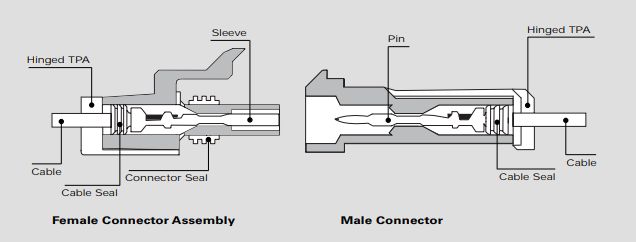
    • RE: Looking for waterproof connectors

      Not sure why the pins do not stay in place. Perhaps they are knock offs.

      You need not seal the back of the connectors, the yellow inserts held by the back of the pin acts as a seal. The Delphi Versions have been used for under vehicle for years with no environmental issue. The location is partially protected (i.e. on top of the fuel tank etc).

      See attached
      0_1525734628236_Clipboard04.jpg

      I would say the irrigation connectors mentioned by NeverDie sounds good, but I'm not familiar with them.

      posted in Hardware
      JohnRob
      JohnRob
    • RE: Nordic or HopeRF radio

      @gohan

      Thank you for the comment. Somehow I was under the impression the NRF24 would accept a 5V for power. However now I see only the inputs are 5V tolerant.

      posted in Hardware
      JohnRob
      JohnRob
    • RE: SCT-013-050 measuring current and appearance power

      From the website the SCT-013-050 outputs 0 to 1 volt for a current of 0 to 50 amps.

      I agree the "burden" resistor is built in on this module.

      Please verify you are only passing one of the coffeemaker wires through the sensor. If you pass the whole cable through the sensor you will get no output voltage from the sensor.

      A typical coffee maker requires ~1000 watts. At 230 vac this is ~4 amps. So the output of the current sensor should be about +/- 4/50*1 = 0.08 volts. This means the arduino has to measure readings from 0 to about 0.11 volts then calculate the RMS. doable but the readings are getting somewhat small to be stable.

      I would suggest:

      1. measure the sensor output with a multimeter if you have one.

      2. Change the reference of A/D converter on the Arduino from the default to the 1.1V internal reference. Not sure the code but you should be able to find it easy enough.

      3. you can increase the output of the sensor by passing the coffee maker wire through multiple times. For each time the wire goes through the sensor the sensitivity is increased by that number.
        for example if you pass the wire through the sensor 3 times. The output becomes 0 to 1 volt for 0 to 50/3 amps .

      4. Add a 0.1ยตF Capacitor across the sensor (where the burden resistor is shown on your diagram. This will remove some of the noise that exists on all AC lines.

      posted in Hardware
      JohnRob
      JohnRob
    • RE: Nordic or HopeRF radio

      I recently started with MySensors. I chose the RFM69W radio over the nrf24 due to posts complaining about range issues with the nrf24. That said I can tell I can tell you the range of my RFM69W is excellent. From my basement (concrete foundation) to the other side of my neighbors house ~75 meters with no issues.

      The only drawback I see is the voltage limit of 3.3Vdc. This precludes using some batteries without a regulator.

      I also found the external antenna could be a + or -. Currently I'm using a coil / spring type antenna mounted on the board.

      posted in Hardware
      JohnRob
      JohnRob
    • RE: Looking for waterproof connectors

      Hi,

      The connectors you referenced look like Delphi 150 type connectors. What about them makes them useless? They work for vehicle use.

      posted in Hardware
      JohnRob
      JohnRob
    • RE: Water pressure sensors?

      @mfalkvidd,

      I'm guessing this is not a hobby request (based on the photo of the manhole cover). I've looked at pressure sensors for level detection many times for automotive applications and can offer the following:

      1. o-rings don't seal. For your application you need either a hermetic seal or fully potted assembly

      2. open tubes will fill / drain based on condensation temperature changes etc.

      3. Freezing is often an issue but I'll guess at you depth you don't have to worry about it.

      Have you considered a pressure switch? It wouldn't necessarily solve the seal problem but might work for you. Still thinking.... the pressure switch might be hard to self test. At least on the pressure you can see small changes, suggesting the transducer is functioning.

      you might find this link useful: submersible transducer

      If you are looking for a lower cost solution, look for "absolute" pressure sensors as opposed to "gauge" pressure sensors.

      If you want to go the potted route, you might look at this: [link text](absolute xducer). If the cabling was completely potted in a suitable material, this could work for you.

      posted in Hardware
      JohnRob
      JohnRob
    • RE: Vera Inclusion Issue

      When I started off and knew nothing about the MySensors system and was in the same spot as you (I didn't know what if anything worked). It was suggested i try the webserver example on the gateway. This would make sure the GW is talking to the LAN.

      Then I made a simple counting sketch on my node that counted from 0 to 250 in steps of 5, sending the count to my VeraPlus using the Multimeter Voltage parameter.

      Maybe this helps.

      posted in Troubleshooting
      JohnRob
      JohnRob
    • RE: Air quality node

      @nca78 said in Air quality node:

      BME680.

      I just purchased a BME680 from "alice1101983" on ebay for $16.85. I figure by the time I receive it I may be ready to start in on a VOC project again.

      BTW the only reason I mentioned alice1101983 is that I've purchased a number of these types of break out boards from this supplier and all the item i received were what I expected and shipped within a reasonable time.

      BTW I do believe all (most) of the breakout boards are mfg by 1 or 2 factories and the folks we see on ebay are small time sellers.

      posted in General Discussion
      JohnRob
      JohnRob
    • RE: Air quality node

      For what i's worth:

      I've not heard of the BME680 but about a year ago I connected a CCS811 to a RasPi.
      I found the readings from the CCS811 less than useful ๐Ÿ˜ž

      At startup it a assumed the air was "clean" It had an algorithm that tried to extract VOC information from their environment sensitive thin film device. You can read all this is their documentation.

      Another note: It required clock stretching on the I2C interface. On the Pi I found a software library that provided a clock stretching capability. The built in I2C would not work reliably. The need for clock stretching came from the CCS811 tech rep. His statement was: "...Can you please check if the processor you are using supports clock stretching and if so please enable this....."

      posted in General Discussion
      JohnRob
      JohnRob
    • RE: Looking for Sensor

      In our area such "speed bumps" are made of asphalt. Is this this the type of structure you are trying to sense a vehicle on?

      If so, I would suggest looking at large metal detectors. In the past I've seen articles on how to construct one for a driveway, however I don't recall the source. In addition, the coil needed for metal detection would be much more robust that putting an active device out in the roadway.

      I'm curious on how you plan to install your device.

      posted in My Project
      JohnRob
      JohnRob
    • RE: Can I troubleshoot my Sensor Code without a radio?

      @mfalkvidd

      Thank you ! that did the trick.

      John

      posted in Troubleshooting
      JohnRob
      JohnRob
    • Can I troubleshoot my Sensor Code without a radio?

      Hi,
      Sensor will be on a Pro mini with an RFM69 radio.

      It would be more convenient for me to develop/troubleshoot my sensor code without the radio. I though of working without MySensors library at this point but I am using the library sleep function.

      Does anyone know if running without the radio is practical?

      Thanks
      John

      posted in Troubleshooting
      JohnRob
      JohnRob
    • RE: Integration of pinChange INT

      @Robert77 ,

      Hi, I too am trying to use the interrupt to capture a water detect event. Can you tell me what you changed in MyHwAVR.cpp? And was there any other special code that I would not find in the Arduino information?

      Thanks

      John

      posted in Development
      JohnRob
      JohnRob
    • RE: [SOLVED] W5100 Ethernet gateway with RFM69 Radio fails at init

      @Falcogeorge

      I have an RFM69 on a Anarduino (basically a AT328p with solder pads for the RFM69. I started with MySensors V2.2.0 My RFM69 NSS is connected to D10. All works fine. My setup code is below.

      One note, the default debug baud is 115k. This is likely too fast for some with lower speed clocks.

      #define MY_DEBUG
      #define MY_BAUD_RATE (9600ul)
      
      // === Hardware / MySensors Initialization ================
      // ========================================================
      #define MY_RADIO_RFM69
      #define MY_RFM69_FREQUENCY RFM69_915MHZ
      #include <MySensors.h>
      
      // === Node Initialization ================================
      // ========================================================
      #define CHILD_ID 5
      #define sensortype S_MULTIMETER
      
      #define LEDPIN 9 //PB1 is pin 9 on ProMini
      #define LED_TST A0
      #define NODE_TXT "Counting_test_Node"  
      
      uint8_t MyCount;
      uint8_t ACK_Result;
      uint8_t NACK_Count;
      
      
      MyMessage msg_Voltage(CHILD_ID, V_VOLTAGE);
      
      posted in Troubleshooting
      JohnRob
      JohnRob
    • RE: [SOLVED] Newbie trying to get RFM69HCW working with ATMEGA328P

      I have an RFM69HW running on a 328P. My code may help.
      You didn't specify your clock rate but if it is a std board running at 3.3V it is probably 8Mhz.
      The default DEBUG baud rate is 115k maybe a little too fast for the 8Mhz.
      I lowered mine to 9600 because I can't read that fast anyway ๐Ÿ™‚

      #define MY_DEBUG
      #define MY_BAUD_RATE (9600ul)
      
      // === Hardware / MySensors Initialization ================
      // ========================================================
      #define MY_RADIO_RFM69
      #define MY_RFM69_FREQUENCY RFM69_915MHZ
      #include <MySensors.h>
      
      // === Node Initialization ================================
      // ========================================================
      #define CHILD_ID 5
      #define sensortype S_MULTIMETER
      
      #define LEDPIN 9 //PB1 is pin 9 on ProMini
      #define LED_TST A0
      #define NODE_TXT "Counting_test_Node"  
      
      uint8_t MyCount;
      uint8_t ACK_Result;
      uint8_t NACK_Count;
      
      
      posted in Troubleshooting
      JohnRob
      JohnRob
    • RE: Is a bootloader worth the limitations?

      @tbowmo

      Thanks for the response. I'll start to the ISP. All my non Arduino AVR projects were all programmed with ISP. I moved to Arduino specifically for MySensors.

      John

      posted in Development
      JohnRob
      JohnRob
    • RE: Is a bootloader worth the limitations?

      @dbemowsk

      Thank for the thought. I am familiar with the 555 (or in this case the 555C) but the WDT should work. BTW if I were to try an external device I would use the TPL5010 as this will be battery powered.

      Back to my point, It would be much easier to just use an ISP than to add an additional circuit. Hence my question, is the boot loaded providing some other function I've not not aware of (mentioned above)?

      posted in Development
      JohnRob
      JohnRob
    • Is a bootloader worth the limitations?

      Hi,

      I'm working on my first to be commissioned node (i.e. not just a test device). I am thinking of using the WDT to reset the system if the processor gets "lost". I am using a Mini Pro board and found the normal WDT reset instructions do not work. My investigation found at least one post that blamed it on the bootloader (not yet verified myself).

      My question is:

      Except for possible OTA reprogramming and maybe a slightly easier programming connection what does a boot loader gain you?
      I realize to perform ISP programming you need a different programmer (I have a AVR MKii clone).

      Am I missing something?

      posted in Development
      JohnRob
      JohnRob
    • RE: some sort of a binary sensor for Vera?

      @korttoma

      Thanks, somehow I was under the impression that the MySensors GitHub devices were all I had to choose from. Your answer make me realize I could use any (most) of the Vera Std sensors.

      John

      posted in Vera
      JohnRob
      JohnRob
    • some sort of a binary sensor for Vera?

      Hi,

      I'm looking to add a water (leak) sensor to my MySensors/Vera system. Looking through the Vera Plugin options I see only analog (variable) plugins. While I know I could use any of them with some sort of value scheme I would prefer to use a binary if possible. Has anyone hacked or created a binary plugin option?

      Thanks

      John

      posted in Vera
      JohnRob
      JohnRob
    • RE: Change PT=1 to PT=0 when changing a sensor state.

      HI,

      I cannot answer your question but if you go to log parser you can see one is sending a string, the other is sending a byte.

      Perhaps this will help.

      John

      posted in Troubleshooting
      JohnRob
      JohnRob
    • RE: Broadcast message received & how can Node handle incoming messages

      @Nca78
      Thank you so much for your incite.

      John

      posted in Troubleshooting
      JohnRob
      JohnRob
    • RE: Broadcast message received & how can Node handle incoming messages

      Hi Nca78,
      Thanks for the enlightening reply. Your response shifted my understanding of what was going on. It wasn't quite an Epiphany but very very helpful.

      BTW I have been using the log parser but I find some of the parsed descriptions are still a bit cryptic. For instance the ACK received message parses to "ACK message, do not proceed but forward to callback".
      Also perhaps you know, when I paste into the parser, only the two rightmost columns contain any entries. Is this just how it is or am I doing something wrong?

      Thanks
      John

      posted in Troubleshooting
      JohnRob
      JohnRob
    • Broadcast message received & how can Node handle incoming messages

      Hi,
      I have a simple system (a sensebender gateway --> VeraPlus and single node that just counts and sends the count every 5 seconds).
      I just added the code to read the results of a send command ( I believe this is the hardware ACK), with the goal of rebooting the node if 10 messages are sent without receiving a ACK. I have not yet started to dig into the software ACK.

      My code has no receive routine (which may be the problem) yet the serial monitor (of the node) reports a "Broadcast message received". I'm not sure what to do with the receipt, I'll assume the gateway wants the node to know something or do something.

      Can someone point me to where I might go to understand the Broadcast message and how to gain the most information from it? And if a receive routine should be added for proper / best usage of MySensors.

      My goal is to understand what conditions can cause a node to stop working and how to either recover or at least notify the controller (VeraPlus)

      Thanks

      John

      the part of my code with the send command:

      
      // Increment count and send message to gateway
          if (MyCount == 255){
      			MyCount = 0;
      			}
      	
          ACK_Result = send(msg_Voltage.set(MyCount),1);
      
      // Test hardware ACK	
      	if (ACK_Result == 1){
      		// blink LED on A0
      		digitalWrite(LED_TST, HIGH);
      		delay(50);
      		digitalWrite(LED_TST, LOW);
      		NACK_Count = 0;
      		}
      	else{
      		NACK_Count = NACK_Count + 1;
      		delay(50);						// keep both loops ~ the same time.
      		}	


      Part of the serial monitor output that shows the message sent and ACK received:

      2140905 TSF:MSG:SEND,1-1-0-0,s=5,c=1,t=38,pt=1,l=1,sg=0,ft=0,st=OK:40  <- node message to GW with payload  (count)= 40
      2141114 TSF:MSG:READ,0-0-1,s=5,c=1,t=38,pt=1,l=1,sg=0:40    <- response from GW reflecting the payload (40)
      2141174 TSF:MSG:ACK                                                                     <- the ACK received (with the MSG:READ??)
      2146034 TSF:MSG:SEND,1-1-0-0,s=5,c=1,t=38,pt=1,l=1,sg=0,ft=0,st=OK:45
      2146243 TSF:MSG:READ,0-0-1,s=5,c=1,t=38,pt=1,l=1,sg=0:45
      2146302 TSF:MSG:ACK
      2148632 TSF:MSG:READ,0-0-255,s=255,c=3,t=20,pt=0,l=0,sg=0:     <- an unsolicited READ coming from GW but how is it recognized by the node?
      2148694 TSF:MSG:BC
      2149895 TSF:MSG:SEND,1-1-0-0,s=255,c=3,t=21,pt=1,l=1,sg=0,ft=0,st=OK:0
      2151163 TSF:MSG:SEND,1-1-0-0,s=5,c=1,t=38,pt=1,l=1,sg=0,ft=0,st=OK:50
      2151372 TSF:MSG:READ,0-0-1,s=5,c=1,t=38,pt=1,l=1,sg=0:50
      2151432 TSF:MSG:ACK
      2156293 TSF:MSG:SEND,1-1-0-0,s=5,c=1,t=38,pt=1,l=1,sg=0,ft=0,st=OK:55
      2156502 TSF:MSG:READ,0-0-1,s=5,c=1,t=38,pt=1,l=1,sg=0:55
      2156561 TSF:MSG:ACK```
      posted in Troubleshooting
      JohnRob
      JohnRob
    • RE: Binary sensor for production counting transmits false values

      Can you describe the physical interface? Could you be receiving spurious signals or as suggested bouncing contacts?

      In my experience with industrial automation, the environment is very electrically noisy. One must include hardware components to protect the MCU from errors and electrical damage.

      Not sure where in the world you are located but in the Northern Hemisphere its winter and ESD is rampant.

      Can you add an LED blink to the MCU board so you can watch the "action" for a sanity check?

      posted in Troubleshooting
      JohnRob
      JohnRob
    • RE: Does Gateway loop() required Wait or delay?

      For those who read this post:

      Since my original post I found the wait(time) command is a MySensors macro that essentially is a "wait millis()" function.

      posted in Development
      JohnRob
      JohnRob
    • RE: Does Gateway loop() required Wait or delay?

      Hi,
      @mfalkvidd

      No I don't, when I first started learning MySensors (not too long ago) I was reading a lot of the website information and posts and whatever. I had the impression an empty loop() routine could be an issue but I must have mixed up what I read on something else. And not really understanding the inner workings of the MySensors code I figured I would ask before I removed the wait(2000) I have.

      So do you recommend nothing or wait(2000) as I have now?

      Thanks

      John

      posted in Development
      JohnRob
      JohnRob
    • Does Gateway loop() required Wait or delay?

      Hi,

      I have a functioning sensebender gateway with one sensor. The sensor is just counting and being used for my 1st system learning.

      My gateway does nothing else but be a gateway. In this configuration do I need a Wait(xx) or delay(xx) in the gateway loop()?

      Early on I thought I read a delay was needed else a lot of unneeded traffic was generated by the gateway, but now I can't find that statement and the examples have no delay in the loop() function.

      Thanks

      posted in Development
      JohnRob
      JohnRob
    • RE: Multimeter recommendation?

      I already had a Fluke 72 (old one with no current range below 10 Amps).

      So for better accuracy, I purchased an HP 3478a digital multimeter on eBay for about $140. It gives me all the accuracy I want (but probably don't need) and has 1 ยตA resolution (accuracy is somewhat less but for tweaking battery usage stability makes it usable.

      Of course it is not as portable as it needs mains power.

      posted in General Discussion
      JohnRob
      JohnRob
    • RE: Sensebender_GW / MYSX 2.6 / SD Card / Sensors on GW

      @gohan,

      Thanks for reading and your response.

      Since posting I've continued to learn and have found the MYSController program which answers my question regarding the convenience to adding sensors to the gateway.

      posted in Hardware
      JohnRob
      JohnRob
    • RE: Best sensor for quantifying magnitude of vibration?

      While not specifically answering your question... would loctite help?
      Or possibly nuts with self locking features (castle etc).

      posted in Hardware
      JohnRob
      JohnRob
    • Sensebender_GW / MYSX 2.6 / SD Card / Sensors on GW

      I'm a recent adopter of MySensors. I have a Sensebender_GW up and running and paired with a VeraPlus. Currently I'm working on the nodes. I do have a node just counting numbers for testing the Gateway to VeraPlus connection.

      My question has to do with the extra capability of the Sensebender_GW (which I like and feel it is a great concept / package). If I'm using the Senesbender_GW as my gateway, what use might i find for the SD Card and MYSX 2.6 connector?

      In a earlier post I learned to have a sensor (aka node) on the gateway one needs a 2nd gateway to pair the sensors on the 1st gateway. This seems like a PIA if you are testing and developing the sensors that are connected to the GW. I'm hoping I'm missing something here, is there more to it?

      posted in Hardware
      JohnRob
      JohnRob
    • RE: Can Gateway perform calculations on sensor data before passing to controller?

      My "concern" is more OCD than realistic. I really have no realistic need to know the temperature as such precision. Its just that I would prefer to get the most accurate reading the sensor is capable of.

      @mfalkvidd

      When you said "....Appendix A does mention that the calculations should use 32-bit signed integers and single or double precision floats. Arduino supports all of them...."

      I was assuming to get 32 bit double precision floats one would need a 32bit ยตP. Am I in error here?

      An old saying (not sure how old).
      A man with one thermometer knows what temperature is.
      A man with two thermometers does not.

      posted in Development
      JohnRob
      JohnRob
    • RE: Solar cell support with non-rechargeable batteries

      It likely does not matter much in this case, however the diodes do consume power.

      Power consumed in diode = voltage across diode X current through diode

      You could reduce the diode voltage drop (not for power savings but for additional usable battery life) if you replaced the 1n4148 with something like a BAS86 (i'm sure there are others).

      posted in My Project
      JohnRob
      JohnRob
    • My First MySensors Project

      Note: This post contains nothing new, all the information presented here is from the MySensors website and / or forum.
      This is an account of my foray into the world of MySensors. I started with absolutely no experience with MySensors, however I have built some AVR and Arduino projects in the past. Comments and corrections are very welcome.

      About me, I am a detail oriented person who feels more comfortable understanding something as opposed to just following directions. This has caused me some consternation with the MySensors as the Arduino platform is designed for those who donโ€™t wish to get into the details (at least not in the beginning).

      My goal:

      I started a MySensors project to add my own sensors to my VeraPlus. I set my immediate goal on a simple configuration:

      • Gateway connected via Ethernet (although a serial gateway would be easier, my VeraPlus has only 1 USB port, it is being used by other hardware and I just didnโ€™t want to add a USB hub)
      • One node reporting a counter value.

      Starting off:

      After reading through much of the MySensors site, I needed to choose the hardware for the Gateway and sensor node.
      The first decisions were the radio and the gateway controller board.

      Radio:

      There are only two commonly used radios with the MySensors system, NRF24 and the RFM69W. Reading through the forums and MySensor page comments folks seemed to experience better connectivity with the RFM69 radio. In addition the NRF24 operates at 2.4 Ghz while the RFM69 was at 915Mhz (for the US). I wanted to stay away from our WiFi and cordless phone frequencies. So I decided to go with the RFM69HW-915. The โ€œHโ€ in HW is for the high power version. As the gateway will be powered by an AC adapter (not batteries), it seemed an easy decision to go with the high power version.

      Radio Antenna:

      Lots of info on the antenna for these radios. For ease in initial testing I choose a simple coil antenna (from ebay). I could further address the antenna once the system was running.

      Gateway:

      The Ethernet version of the gateway requires more cpu capability than the serial version. Folks said I would need a Mega2560. I started down that road then realized the Mega2560 was a 5V device and the RFM69HW was a 3.3V device and the inputs were not 5V tolerant. I could have used level adapters but the wiring would start to get ugly. Then I started to look and the Arduino Zero which has plenty of capacity. Reading further I found the MySensors system stores the Node IDโ€™s in EE memory which is lacking on the Zero! Hmmm. I then looked at the Sensebender GW. This board is designed for the MySensors system using the same processor as the Arduino Zero and has EE memoryโ€ฆ.perfect! So that was the direction I went. Besides the Sensebender GW makes a very nice package.
      BTW Later I found the MySensors Node IDโ€™s were not written all that often so I could have stayed with the Zero which can store data in its flash memory. But I do not regret going with the Sensebender GW as it makes a real nice package.

      Ethernet Adapter:

      Once the Sensebender GW was chosen, the Ethernet board was easy. We use the W5100 that plugs right into the GW.

      Node Hardware:

      Well we already know the radio will be a RFM69HW-915 (high power) or the RFM69W-915 (standard power). I could have easily used an Arduino Pro Mini (3.3V / 8 Mhz). However I found the Anarduino MiniWireless which would make a very neat package (see a trend here).
      I purchased their โ€œ-W-915 RFM69W 915Mhzโ€ board. It presents a nice clean assembly and comes with the radio installed. For those who wish to โ€œroll their ownโ€ and assemble the radio to a CPU board, I expect it is not a difficult proposition.

      Assembling the hardware:

      Note about my assembly. Iโ€™ve been building electronic devices for some time. Iโ€™m lucky enough to have a decent ESD mat (you will see the blue background in the photos) and a good soldering iron.
      For the node all I had to do was to solder the antenna and wires for power.

      Now with the remaining hardware on hand the next step was to assemble the gateway (aka GW).

      My gateway parts:_
      0_1518223974872_01_Starting Parts-small.JPG
      Radio, Sensebender_GW, Ethernet Adapter

      === PHOTO === PARTS ===

      _Soldering the radio: _

      I used 0.020โ€ diameter no-clean 63/37 solder. While this is not โ€œno leadโ€ solder, it is best for hand soldering many parts. The reason is that 63/37 has no solidus phase which means it essentially goes from liquid to solid reducing the possibility of โ€œcoldโ€ solder joints. The diameter is not critical, however the small solder diameter makes it much easier to control the solder amount and get nice looking joints. If you are not good at soldering small parts I suggest you get some small diameter solder.

      Soldering the radio to the gateway

      0_1518224003534_02_Soldering Radio-small.JPG
      === PHOTO ==== Soldering radio ===

      Ethernet Header:

      When soldering the Ethernet (W5100) header, the instructions on the MySensors website tells you to raise the header as high as possible. Because the Ethernet jack is taller than the header socket. When doing this be sure you can see the outline of the header pins through the solder. If not you could have a condition where the solder bridges the hole and not reaches the pin. This would result in a poor connection which if it becomes intermittent could be a bear to troubleshoot.
      0_1518224227780_04_SolderedW5100Header-small.JPG
      === PHOTO === Ethernet header ===

      One issue I found when installing the Ethernet board was a possible interference between a resistor on the gateway board and the metal Ethernet jack housing. I put two layers of Kapton tape on the jack housing to keep them from shorting.

      0_1518224087435_08_TapeW5100-small.JPG

      The Final Gateway Assembly:
      0_1518224504580_Sensebender GW Complete_06.JPG
      0_1518224533870_Sensebender GW Complete_02.JPG

      The Final Node Assembly:

      0_1518224546317_Node ID5, Complete.JPG

      === PHOTO === Final Assemblies ===

      Testing the Gateway

      One of the problems with a project like this is the inability to test each piece. When starting off one has no radio to test the radio function. However it was suggest by
      tbowmo to try the example "Examples/Ethernet/WebServer" ? to prove that the Ethernet module is up and running.
      In addition, zboblamont pointed me to this site to decipher the serial monitor messages is via the log parser, https://www.mysensors.org/build/parser

      Software:

      I am using Arduino IDE 1.8.5
      I started on the gateway software first. It turns out my detailed approach did not help me. For me the Arduino approach of using the original Arduino Uno board numbers for pin references was too abstract. Iโ€™m used to being able to look and the cpu datasheet and finding the info I needed. This was especially so with the Sensebender GW which used a whole bunch of pins that did not exist on the Uno. Have no fear, it all worked out.
      See here for the MySensors information and how to install the Sensebender GW board code in the Arduino IDE Sensebender Gateway instructions.

      Gateway Code:

      Attached is my gateway code. Iโ€™ve annotated any changes made to the original found at Ethernet gateway. All my changes are preceded by **** you can see them in the listing. As you can see I needed to make only a few โ€œselectionsโ€ for the hardware I am using.

      // GatewayCode_004b  Compiles with Lib V2.2.0 2018-01-31
      // was MySensorsGateW5100Code modified V01b   (compiles, this will become our Gateway code!)
      // it seems the GatewayCode_003 had problems, likely because we made some erroneous modification.
      
      // In future consider including some Sensebender_GW routines found in the
      //  example: %user%\Documents\Arduino\libraries\MySensors\examples\SensebenderGatewaySerial.ino
      
      /**
       * The MySensors Arduino library handles the wireless radio link and protocol
       * between your home built sensors/actuators and HA controller of choice.
       * The sensors forms a self healing radio network with optional repeaters. Each
       * repeater and gateway builds a routing tables in EEPROM which keeps track of the
       * network topology allowing messages to be routed to nodes.
       *
       * Created by Henrik Ekblad <henrik.ekblad@mysensors.org>
       * Copyright (C) 2013-2015 Sensnology AB
       * Full contributor list: https://github.com/mysensors/Arduino/graphs/contributors
       *
       * Documentation: http://www.mysensors.org
       * Support Forum: http://forum.mysensors.org
       *
       * This program is free software; you can redistribute it and/or
       * modify it under the terms of the GNU General Public License
       * version 2 as published by the Free Software Foundation.
       *
       *******************************
       *
       * REVISION HISTORY
       * Version 1.0 - Henrik EKblad, contirbutions by, a-lurker, Anticimex,
       *               Norbert Truchsess <norbert.truchsess@t-online.de>
       *               and Tomas Hozza <thozza@gmail.com>
       *
       *
       * DESCRIPTION
       * The EthernetGateway sends data received from sensors to the ethernet link.
       * The gateway also accepts input on ethernet interface, which is then sent out to the radio network.
       *
       * The GW code is designed for Arduino 328p / 16MHz. Could be why the Anarduino MiniWirelessW pushes the 3.3V 328p to 16Mhz
       *
       * LED purposes:
       * - To use the feature, uncomment MY_DEFAULT_xxx_LED_PIN in the sketch below
       * - RX (green) - blink fast on radio message received. In inclusion mode will blink fast only on presentation received
       * - TX (yellow) - blink fast on radio message transmitted. In inclusion mode will blink slowly
       * - ERR (red) - fast blink on error during transmission error or receive crc error
       *
       * See http://www.mysensors.org/build/ethernet_gateway for wiring instructions.
       *
       */
      
      // Enable debug prints to serial monitor
      #define MY_DEBUG
      
      // Enable and select radio type attached
      //#define MY_RADIO_NRF24
      //#define MY_RADIO_NRF5_ESB
      #define MY_RADIO_RFM69						// **** select the RFM69 radio
      //#define MY_RADIO_RFM95
      #define MY_RFM69_FREQUENCY RFM69_915MHZ     // **** added from forum suggestion
      #define MY_IS_RFM69HW						// **** added from forum suggestion
      #define MY_DEBUG_VERBOSE_RFM69
      
      // Enable gateway ethernet module type
      #define MY_GATEWAY_W5100
      
      // W5100 Ethernet module SPI enable (optional if using a shield/module that manages SPI_EN signal)
      #define MY_W5100_SPI_EN 4					// **** enable as the W5100 does not manage the EN signal, the Arduino "ethernet shield" does.
      
      // Enable Soft SPI for NRF radio (note different radio wiring is required)
      // The W5100 ethernet module seems to have a hard time co-operate with
      // radio on the same spi bus.
      #if !defined(MY_W5100_SPI_EN) && !defined(ARDUINO_ARCH_SAMD)
      #define MY_SOFTSPI
      #define MY_SOFT_SPI_SCK_PIN 14
      #define MY_SOFT_SPI_MISO_PIN 16
      #define MY_SOFT_SPI_MOSI_PIN 15
      #endif
      
      // When W5100 is connected we have to move CE/CSN pins for NRF radio
      //									  	**** I was confused here as the comment references the W5100 which we have but the code only "talks" to the RF24 radio
      //										**** it turns out this is not an issue so don't worry about it.
      #ifndef MY_RF24_CE_PIN
      #define MY_RF24_CE_PIN 5
      #endif
      #ifndef MY_RF24_CS_PIN
      #define MY_RF24_CS_PIN 6
      #endif
      
      // Enable UDP communication
      //#define MY_USE_UDP  // If using UDP you need to set MY_CONTROLLER_IP_ADDRESS below
      
      // Enable MY_IP_ADDRESS here if you want a static ip address (no DHCP)
      #define MY_IP_ADDRESS 192,xxx,xxx,xxx			//**** added my desired ip address for the gateway
      
      // If using static ip you can define Gateway and Subnet address as well
      #define MY_IP_GATEWAY_ADDRESS 192,xxx,xxx,xxx	//**** added the ip address of my router
      #define MY_IP_SUBNET_ADDRESS 255,255,255,0
      
      // Renewal period if using DHCP
      //#define MY_IP_RENEWAL_INTERVAL 60000
      
      // The port to keep open on node server mode / or port to contact in client mode
      #define MY_PORT 5003
      
      // Controller ip address. Enables client mode (default is "server" mode).
      // Also enable this if MY_USE_UDP is used and you want sensor data sent somewhere.
      //#define MY_CONTROLLER_IP_ADDRESS 192, 168, 178, 254
      
      // The MAC address can be anything you want but should be unique on your network.
      // Newer boards have a MAC address printed on the underside of the PCB, which you can (optionally) use.
      // Note that most of the Ardunio examples use  "DEAD BEEF FEED" for the MAC address.
      #define MY_MAC_ADDRESS 0xDE, 0xAD, 0xBE, 0xEF, 0xFE, 0xED
      
      // Enable inclusion mode
      #define MY_INCLUSION_MODE_FEATURE
      // Enable Inclusion mode button on gateway
      //#define MY_INCLUSION_BUTTON_FEATURE
      // Set inclusion mode duration (in seconds)
      #define MY_INCLUSION_MODE_DURATION 60
      // Digital pin used for inclusion mode button
      //#define MY_INCLUSION_MODE_BUTTON_PIN  3
      
      // Set blinking period
      #define MY_DEFAULT_LED_BLINK_PERIOD 300
      
      // Flash leds on rx/tx/err
      // Uncomment to override default HW configurations
      //#define MY_DEFAULT_ERR_LED_PIN 7  // Error led pin
      //#define MY_DEFAULT_RX_LED_PIN  8  // Receive led pin
      //#define MY_DEFAULT_TX_LED_PIN  9  // Transmit led pin
      
      #if defined(MY_USE_UDP)
      #include <EthernetUdp.h>
      #endif
      #include <Ethernet.h>
      #include <MySensors.h>
      
      void setup()
      {
      	// Setup locally attached sensors
      }
      
      void presentation()
      {
      	// **** I was originally going to add a sensor to the gateway but did not know how to include it so the idea was abandon.
      }
      
      void loop()
      {
      	
        wait(2000);					// **** not sure this is required / helps / hurts
      }
      

      ================= gateway code========================

      To download the code to the Sensebender GW in the Arduino IDE I selected:

      • Tools / Board: Sensebender Gateway
      • Tools / Port: whatever port your computer assigns to the Sensebender board.
      • Tools / Programmer: Arduino as ISP (I donโ€™t think this matters)
      • Press the Arduino IDE _upload_ icon.   Sorry, I think of programming the board as downloading, Arduino defines it as upload.  Both the same function.
        

      At this point I could โ€œseeโ€ the IP address in my router under โ€œwired connectionsโ€.
      I could also โ€œpingโ€ it from the PC command prompt. So I know the controller and W5100 were working fine as I believe the ping return requires the CPU software (but not sure).

      Node Code:

      // Sensor node code -  Use Multimeter but send loop counts for volts
      // 2018-02-01  V_01a
      // Target: Aarduino MiniWirelessW-915
      // MySensors Library V2.2.0
      // from:  https://www.mysensors.org/download/sensor_api_20
      
      // IDE Configuration:
      //  Board: Duemilanlove
      //  Programmer:  AVR ISP
      
      #define MY_DEBUG
      
      // *** Hardware / MySensors Initialization *** //
      #define MY_RADIO_RFM69
      #define MY_RFM69_FREQUENCY RFM69_915MHZ
      #include <MySensors.h>
      
      // *** Node Initialization *** //
      #define CHILD_ID 5
      #define sensortype S_MULTIMETER
      
      #define analoginputPIN A0
      #define LEDPIN 9 //PB1 is pin 9 on ProMini
      #define NODE_TXT "Initial_JohnRob_Node"  
      uint8_t MyCount;
      
      MyMessage msg_Voltage(CHILD_ID, V_VOLTAGE);
      
      void setup()
      {
      pinMode(LEDPIN, OUTPUT);
        delay(1);                     // was in example where the setup() was empty, likely adds some timing safety margin
      }
      
      void presentation()
      {
      // Send the sketch version information to the gateway and Controller
        sendSketchInfo(NODE_TXT, "01a");
        present(CHILD_ID, S_MULTIMETER);
      //  DEBUG_PRINTLN(F("Sensor Presentation Complete"));  // commented out because I don't know how to use this feature.
      }
      
      void loop()
      {
      // Toggle LED
        asm ("sbi %0, %1 \n": : "I" (_SFR_IO_ADDR(PINB)), "I" (PINB1)); // Toggle LED
        
        // a simple counter to be used for troubleshooting and radio range testing
      	if (MyCount < 255){
      		send(msg_Voltage.set(MyCount));
      		}
      	else {
      		MyCount = 0;
      		send(msg_Voltage.set(MyCount));
      		}
          MyCount = MyCount + 5; 
        
        wait(5000);    //unsigned long 
      }
      

      The node code is very simple. I used the S_Multimeter sensor type to relay a simple count by 5, wrapping to 0 at 250. Because the Anarduino Iโ€™m using runs the 328p at 16Mhz, you have to use the Duemilanlove as board type.
      I downloaded the node code using a FTDI USB to TTL board (with a real FTDI chip). Programming was simple.

      === Node Code ===

      Pairing the Gateway to VeraPlus

      I have a VeraPlus using UI7. I paired the gateway with the Vera by following the instructions here =============Connect to Vera link=============
      The only difference I found was the instructions are for the Vera UI5 but the steps are the same. Also, when I downloaded the Vera Plugin from Github as a zip, the sensors we each in a subdirectory so one simply has to add the required files from each subdirectory or move all to one directory.
      I ended up with a device in Vera that looked like this:
      0_1518224384550_Vera - MySensor.jpg
      ===Vera MySensor device ===

      In the above device under โ€œsettingsโ€ I found the below screen:

      0_1518224586399_Include.jpg
      === Vera Include Screen ===

      How I included my node:

      • Turn off power to the node.
      • Press the โ€œStartโ€ button in Vera (see above)
      • You will see 0 devices found
      • Power on the Node
      • In a few moments you will see 2 devices found.
      • I waited for the inclusion to time out

      Vera then showed two new devices: (see below)

      0_1518224602347_Devices.jpg

      === Vera device screenshots ===

      The Multimeter is only setup to report Volts (see node code). The displayed value incremented in steps of 5 as programmed by the node code.

      All worked well!! Amazing.

      Range testing:

      Clearly not a scientific test but Iโ€™ll describe my longest range tested.
      I live in a 1 family house, the houses are about 30 to 50โ€™ apart. My gateway was in my basement; I carried the sensor node to the opposite side of my neighborโ€™s home and was getting a usable signal. So I decided to keep the spring type antenna for both the Gateway and Node.

      _Conclusion: _

      The MySensors concept can be a little intimidating at first, especially given the breath of hardware one could choose from. But HEK and contributors did an amazing job of creating and executing the concept.
      As I said in the beginning, I offer no original content, just recounting my reasoning and steps in the hope that it will speed the initial steps of those who follow and maybe help some continue when they would otherwise abandon the MySensors concept.

      _Next Steps: _

      I have a housing on order for the gateway. I'm still thinking about how to mount the boards so the connections are available.
      For the nodes, I plan on investigating how low I can get the current of Anarduino MiniWireless before planning any battery operated nodes.

      posted in My Project
      JohnRob
      JohnRob
    • RE: How to connect gateway sensor to Vera

      @Tomas,

      Thank you ๐Ÿ™‚
      I took me awhile to comprehend what you were saying but I think I understand now.

      posted in Vera
      JohnRob
      JohnRob
    • RE: Can Gateway perform calculations on sensor data before passing to controller?

      @rejoe2 said in Can Gateway perform calculations on sensor data before passing to controller?:

      STM32F103

      HI, Thanks for the insight and the ref to the ST board, I was not aware of its existence.

      Regarding the BME280 my original BME test was on a RasPi using Python, which seems to be capable of very long numbers. I did not use any library and coded it from the datasheet.

      Reading the datasheet, Bosch recommends a 32bit processor. See datasheet Appendix A.
      In any case the polynominals used for calculating the final temperature, humidity and pressure are quite long and small errors in the calculation will have some effect on the result / accuracy. How much...I don't know but for me a little OCD is enough to want the best I can do.

      If I ever quantify the error I will try to update this thread.

      posted in Development
      JohnRob
      JohnRob
    • Can Gateway perform calculations on sensor data before passing to controller?

      I would like to have a Bosch BME280 in a remote location controlled by a Sensebender Micro (or similar). The processing math for this sensor demands a 32 bit processor for accuracy (I don't know the actual error in using a 8 bit but I believe Bosch's recommendations).

      My Gateway is a Sensebender_GW.

      Is there a way for the remote Node to read the raw BME280 data and pass it to the Gateway for computing/processing, then be sent to the controller?

      Thanks
      John

      posted in Development
      JohnRob
      JohnRob
    • RE: Redefinition warning when Compiling for RFM69W-915 Radio

      @mfalkvidd said in Redefinition warning when Compiling for RFM69W-915 Radio:

      MySensors.h

      Thank you.

      I was under the impression that the RFM69 default frequency was 868Mhz and if I placed the "#define MY_RFM69_FREQUENCY RF69_915MHZ" before the MySensors.h the frequency would be reset to 868.

      I'm guessing by your answer that this is not the case. Perhaps an if not defined.

      posted in Development
      JohnRob
      JohnRob
    • RE: RFM69HW in MySensors 2.2.0

      I had asked the same question but before V2.2.0
      See this post:

      RFM69

      posted in Development
      JohnRob
      JohnRob
    • Redefinition warning when Compiling for RFM69W-915 Radio

      Hi,
      I'm working on my first MySensors Node. My code is a simple read an analog input function. Now because my radio is a 915MHz version I must add a line to state such. When I do the compiler gives me a warning "warning: "MY_RFM69_FREQUENCY" redefined"

      Now I know I am redefining the default radio frequency so the warning is understood, however I am wondering if I am coding is a clumsy manor to get this warning.
      My Code:

      // Sensor node code
      // 2018-01-26  V_01b
      // Target: Aarduino MiniWirelessW-915
      //MySensors API V2.2.0
      // from:  https://www.mysensors.org/download/sensor_api_20
      
      
      #define MY_DEBUG
      // *** Initialization *** //
      #define MY_RADIO_RFM69
      #include <MySensors.h>
      
      #define MY_RFM69_FREQUENCY RF69_915MHZ
      #define CHILD_ID 5
      #define sensortype S_MULTIMETER
      #define analoginputPIN A0
      #define LEDPIN 9 //PB1 is pin 9 on ProMini
      
      uint16_t analogPinRdg;
      
      MyMessage msg_Voltage(CHILD_ID, V_VOLTAGE);
      
      void setup()
      {
      pinMode(LEDPIN, OUTPUT);
      digitalWrite(LEDPIN, HIGH);   // turn the LED on (doesn't work, may not get here)
      }
      
      void presentation()
      {
        present(CHILD_ID, S_MULTIMETER);
      }
      
      
      void loop()
      {
        
      //  digitalWrite(LEDPIN, HIGH);   // turn the LED on (HIGH is the voltage level)
      //  delay(1000);                       // wait for a second
      //  digitalWrite(LEDPIN, LOW);    // turn the LED off by making the voltage LOW
          delay(1000);                       // wait for a second
        
        asm ("sbi %0, %1 \n": : "I" (_SFR_IO_ADDR(PINB)), "I" (PINB1)); // Toggle LED
        analogPinRdg = analogRead(analoginputPIN);
        send(msg_Voltage.set(analogPinRdg));
        
      
        wait(5000);    //unsigned long 
      }```
      posted in Development
      JohnRob
      JohnRob
    • RE: Cannot get Sensebender_GW / W5100 to connect to router.

      @gohan,

      Thanks I see that now. After I commented out the IP address the router assigned (dhcp) an address.

      All seems to be working now. I still have to wait to get my sensor board going to test the actual communication. I had been hoping to perform the initial test of data from the gateway Analog input to my VeraPlus, however I don't know how to include a sensor on the gateway.

      JohnRob

      posted in Development
      JohnRob
      JohnRob
    • RE: Cannot get Sensebender_GW / W5100 to connect to router.

      @tomkxy,

      I can't say exactly what is happening but the router does not show the MySensors gateway in the DHCP Client list. However, both the Webserver example and the Sensebender_GW are running through the router.

      1. The webserver example output can be seen by directing Chrome to the Webserver IP address.

      2. The Sensebender_GW can connect to my VeraPlus which is connected to the LAN.

      I have a feeling that the MySensor code is designed to connect - send payload - disconnect. However I don't currently know how to test this or if its even a possibility.

      For me right now, the lack of Router listing is not an issue as I still have a ways to go to setup my 1st sensor -> VeraPlus network.

      posted in Development
      JohnRob
      JohnRob
    • RE: Cannot get Sensebender_GW / W5100 to connect to router.

      Many thanks for both replies.

      I tried the Ethernet/Webserver and found the hardware OK. The issue appears to be the operator not knowing what to expect from the Gateway.

      I found the response parser, however I'm still too much a novice to put the message information to good use.

      posted in Development
      JohnRob
      JohnRob
    • How to connect gateway sensor to Vera

      Hi,
      I'm just starting with MySensors. I've build a gateway based on:
      Sensebender_GW
      W5100
      RFM69

      My plan was to start out with a simple "read analog pin" sensor located on the GW.

      The GW is running, and I have the MySensors Plugin recognized by Vera and reporting connected.

      I based my node addition to the gateway on this code from the Mihai post sensor on gateway reference

      My issue is, I don't know how to create a MySensors sensor device on Vera. I can't use the normal include procedure as the sensor is on the gateway. But I tried anyway. by starting inclusion and resetting the gateway but to no avail.

      Any input would be appreciated.

      posted in Vera
      JohnRob
      JohnRob
    • Cannot get Sensebender_GW / W5100 to connect to router.

      Hi,

      I've built a gateway using:
      Sensebender GW
      W5100 Ethernet board (the small board, not the arduino shield)
      RFM69HW 915Mhz.

      At the moment I have no sensor nodes. My plan was to get the gateway talking to the router, then add a potientiometer to the gateway (simple analog read of the wiper) to wring out the connection to my VeraPlus.

      I connected it up and making a few modifications to the example code "GatewayW5100.ino". Downloaded the code to the GW board and could not get it to connect to my router.

      I setup a MAC IP reservation on my router.
      I triple checked the MAC address.

      the result was:
      No connection shown on my router

      Serial monitor showed:
      0;255;3;0;9;MCO:BGN:STP
      0;255;3;0;9;MCO:BGN:INIT OK,TSP=1

      I don't know where to look next. Is there a documentation that will decipher the debug info shown in the serial port monitor?

      Thanks
      JohnRob

      my code: (I annotated any changes from the downloaded code)

      /**
       * The MySensors Arduino library handles the wireless radio link and protocol
       * between your home built sensors/actuators and HA controller of choice.
       * The sensors forms a self healing radio network with optional repeaters. Each
       * repeater and gateway builds a routing tables in EEPROM which keeps track of the
       * network topology allowing messages to be routed to nodes.
       *
       * Created by Henrik Ekblad <henrik.ekblad@mysensors.org>
       * Copyright (C) 2013-2015 Sensnology AB
       * Full contributor list: https://github.com/mysensors/Arduino/graphs/contributors
       *
       * Documentation: http://www.mysensors.org
       * Support Forum: http://forum.mysensors.org
       *
       * This program is free software; you can redistribute it and/or
       * modify it under the terms of the GNU General Public License
       * version 2 as published by the Free Software Foundation.
       *
       *******************************
       *
       * REVISION HISTORY
       * Version 1.0 - Henrik EKblad
       * Contribution by a-lurker and Anticimex,
       * Contribution by Norbert Truchsess <norbert.truchsess@t-online.de>
       * Contribution by Tomas Hozza <thozza@gmail.com>
       *
       *
       * DESCRIPTION
       * The EthernetGateway sends data received from sensors to the ethernet link.
       * The gateway also accepts input on ethernet interface, which is then sent out to the radio network.
       *
       * The GW code is designed for Arduino 328p / 16MHz.  ATmega168 does not have enough memory to run this program.
       *
       * LED purposes:
       * - To use the feature, uncomment MY_DEFAULT_xxx_LED_PIN in the sketch below
       * - RX (green) - blink fast on radio message recieved. In inclusion mode will blink fast only on presentation recieved
       * - TX (yellow) - blink fast on radio message transmitted. In inclusion mode will blink slowly
       * - ERR (red) - fast blink on error during transmission error or recieve crc error
       *
       * See http://www.mysensors.org/build/ethernet_gateway for wiring instructions.
       *
       */
      
      // Enable debug prints to serial monitor
      #define MY_DEBUG
      
      // Enable and select radio type attached
      //#define MY_RADIO_NRF24
      #define MY_RADIO_RFM69            // enabled
      
      #define MY_RFM69_FREQUENCY RF69_915MHZ      // <-- added, info from forum
      #define MY_IS_RFM69HW                       // <-- added, info from forum
      
      // Enable gateway ethernet module type
      #define MY_GATEWAY_W5100
      
      // W5100 Ethernet module SPI enable (optional if using a shield/module that manages SPI_EN signal)
      #define MY_W5100_SPI_EN 4                               //<   <---- enabled this line after not response without
      
      // Enable Soft SPI for NRF radio (note different radio wiring is required)
      // The W5100 ethernet module seems to have a hard time co-operate with
      // radio on the same spi bus.
      #if !defined(MY_W5100_SPI_EN) && !defined(ARDUINO_ARCH_SAMD)
      #define MY_SOFTSPI
      #define MY_SOFT_SPI_SCK_PIN 14
      #define MY_SOFT_SPI_MISO_PIN 16
      #define MY_SOFT_SPI_MOSI_PIN 15
      #endif
      
      // When W5100 is connected we have to move CE/CSN pins for NRF radio
      #ifndef MY_RF24_CE_PIN
      #define MY_RF24_CE_PIN 5
      #endif
      #ifndef MY_RF24_CS_PIN
      #define MY_RF24_CS_PIN 6
      #endif
      
      // Enable to UDP
      //#define MY_USE_UDP
      
      #define MY_IP_ADDRESS 192,xxx,xxx,xx7   // If this is disabled, DHCP is used to retrieve address    <-- changed to reserved IP 
      // Renewal period if using DHCP
      //#define MY_IP_RENEWAL_INTERVAL 60000
      // The port to keep open on node server mode / or port to contact in client mode
      #define MY_PORT 5003
      
      // Controller ip address. Enables client mode (default is "server" mode).
      // Also enable this if MY_USE_UDP is used and you want sensor data sent somewhere.
      //#define MY_CONTROLLER_IP_ADDRESS 192, 168, 178, 254
      
      // The MAC address can be anything you want but should be unique on your network.
      // Newer boards have a MAC address printed on the underside of the PCB, which you can (optionally) use.
      // Note that most of the Ardunio examples use  "DEAD BEEF FEED" for the MAC address.
      #define MY_MAC_ADDRESS 0xFE, 0xED, 0xDE, 0xAD, 0xBE, 0xEF                   //<-- changed to not be default.
      
      // Enable inclusion mode
      #define MY_INCLUSION_MODE_FEATURE
      // Enable Inclusion mode button on gateway
      //#define MY_INCLUSION_BUTTON_FEATURE
      // Set inclusion mode duration (in seconds)
      #define MY_INCLUSION_MODE_DURATION 60
      // Digital pin used for inclusion mode button
      //#define MY_INCLUSION_MODE_BUTTON_PIN  3
      
      // Set blinking period
      #define MY_DEFAULT_LED_BLINK_PERIOD 300
      
      // Flash leds on rx/tx/err
      // Uncomment to override default HW configurations
      //#define MY_DEFAULT_ERR_LED_PIN 7  // Error led pin
      //#define MY_DEFAULT_RX_LED_PIN  8  // Receive led pin
      //#define MY_DEFAULT_TX_LED_PIN  9  // Transmit led pin
      
      
      #if defined(MY_USE_UDP)
      #include <EthernetUdp.h>
      #endif
      #include <Ethernet.h>
      #include <MySensors.h>
      
      
      void setup()
      {
      }
      
      void loop()
      {
      }```
      posted in Development
      JohnRob
      JohnRob
    • RE: Best way to provide power to my Sensebender GW

      Thanks to both ๐Ÿ™‚

      The reason I asked was some time back I was playing with a RasPi board and found the micro-usb to be very unreliable.

      JohnRob

      posted in Hardware
      JohnRob
      JohnRob
    • Best way to provide power to my Sensebender GW

      Hi,

      I'm currently assembling my Sensebender Gateway with W5100 Ethernet module and RM69HW radio. I would like to know other's experience powering this combination.

      I could use a phone charger through the Micro USB, but I'm concerned the radio might take too much power (when xmitting) than the thin wire and mall connector (micro USB) provided by the charger.

      Other option is 5V in through the MYSX connector.

      Thanks

      posted in Hardware
      JohnRob
      JohnRob
    • Is there a minimum clksys speed for gateway or nodes?

      Hi,

      I'm curious to know if there is some practical minimum system clock speed for either a gateway or node?

      At the moment I don't have any battery operated nodes but I plan on having them in the future. It just seems like something that would be good to know when planning a design.

      Thanks

      John

      posted in General Discussion
      JohnRob
      JohnRob
    • RE: Programming needed to enable RFM69 radio with 5100 ethernet code.

      @korttoma
      Thanks I just make the changes you suggested.
      However I'm still uncomfortable not knowing how the pins get sorted out by the software.

      JohnRob

      posted in Development
      JohnRob
      JohnRob
    • RE: Efficient LEDs for night light?

      I've added LED strips under my stair threads for night use. I've learned the "Daylight" (most blue / harsh of the white) is the most efficient. It seems to make the "warm" whites some of the brightness is "consumed".

      My lights are running at ~ 1% on time (153 hz) and work great at night. There are 6 meters of light consuming 0.5 watts (including the AC adapter). The cost of the LED strips is trivial. Look on ebay, you can probable get 2 or 3 different kinds for < $10 total and see which you like best.

      posted in General Discussion
      JohnRob
      JohnRob
    • RE: Why I quit using MySensors for actuators

      Hi, I know I'm a little late to this thread. I'm just starting with MySensors and am learning by reading the posts.

      Currently I am waiting for hardware for my 1st gateway so I am not encumbered by details.

      I notice in all the reported cases the "problem" node is AC powered, while many of the "good" sensor nodes are battery powered. Could this be significant? It would be interesting if someone with a "problem" actuator node could put a battery operated sensor node in the same area.

      Just a thought.

      posted in General Discussion
      JohnRob
      JohnRob
    • RE: does MySensors use a guaranteed transport protocol or a best effort ?

      I'm just starting with MySensors so here I'm just thinking at a system level.
      I have two suggestions / questions regarding the status of "important" nodes.

      1. is it not possible to pole the sensor and request status?

      2. If in this case the the valve controlling node could be programmed to report the status of the valve at an increased rate when it is "on". Or perhaps better, increase the report rate for a time after shutting off.

      posted in General Discussion
      JohnRob
      JohnRob
    • RE: Programming needed to enable RFM69 radio with 5100 ethernet code.

      Thanks the information was helpful. But I'm still hung up on the pin designators. In this code:

      // Enable debug prints to serial monitor
      #define MY_DEBUG
      
      // Enable and select radio type attached
      //#define MY_RADIO_NRF24
      #define MY_RADIO_RFM69
      
      // Enable gateway ethernet module type
      #define MY_GATEWAY_W5100
      
      // W5100 Ethernet module SPI enable (optional if using a shield/module that manages SPI_EN signal)
      #define MY_W5100_SPI_EN 4
      
      // Enable Soft SPI for NRF radio (note different radio wiring is required)
      // The W5100 ethernet module seems to have a hard time co-operate with
      // radio on the same spi bus.
      #if !defined(MY_W5100_SPI_EN) && !defined(ARDUINO_ARCH_SAMD)
      #define MY_SOFTSPI
      #define MY_SOFT_SPI_SCK_PIN 14
      #define MY_SOFT_SPI_MISO_PIN 16
      #define MY_SOFT_SPI_MOSI_PIN 15
      #endif
      
      // When W5100 is connected we have to move CE/CSN pins for NRF radio
      #ifndef MY_RF24_CE_PIN
      #define MY_RF24_CE_PIN 5
      #endif
      #ifndef MY_RF24_CS_PIN
      #define MY_RF24_CS_PIN 6
      #endif
      

      Here I'm struggling, because the Sensebender_GW does not wire the RF24 pins to pin 5 & 6 as shown in the above code (based one the Github schematic ) So as I try to understand how to code the RFM69 I'm lost as to what pins need to be defined in the sketch.

      In the old days I would simply pickup the CPU datasheet and be good to go, however the Arduino pin mapping has me completely baffled. Even after reading every variant.h on my computer!

      So I thought if someone could post the code for the same configuration I would using, I could go backwards and learn the pin mapping.

      posted in Development
      JohnRob
      JohnRob
    • Programming needed to enable RFM69 radio with 5100 ethernet code.

      Can someone suggest a sketch code that would work with a sensebender_Gw. Using a RFW69 radio and a 5100 enternet.

      posted in Development
      JohnRob
      JohnRob
    • (newbie) Pin confusion between example and board pins

      HI,
      Am making a Sensebender based gateway with Ethernet and RFM69 radio and while I'm waiting for the hardware I am trying to get the gateway sketch sorted out.
      My confusion has to do with the stated SPI Issue between the W5100 and anything else on the SPI bus.

      Specifically in this part of the code:

      // Enable Soft SPI for NRF radio (note different radio wiring is required)
      // The W5100 ethernet module seems to have a hard time co-operate with
      // radio on the same spi bus.
      #if !defined(MY_W5100_SPI_EN) && !defined(ARDUINO_ARCH_SAMD)  <--------- Line 1
      #define MY_SOFTSPI
      #define MY_SOFT_SPI_SCK_PIN 14
      #define MY_SOFT_SPI_MISO_PIN 16
      #define MY_SOFT_SPI_MOSI_PIN 15
      #endif
      
      // When W5100 is connected we have to move CE/CSN pins for NRF radio    <--- Section 2
      #ifndef MY_RF24_CE_PIN
      #define MY_RF24_CE_PIN 5
      #endif
      #ifndef MY_RF24_CS_PIN
      #define MY_RF24_CS_PIN 6
      #endif
      

      The comment lines state the W5100 is the module with the SPI "issue"
      In line 1 it seems to result in not defining the soft SPI if the CPU is a SAMD (which the Sensebender is)

      In Section 2 no mention is made for the RFM69 radio.

      My question is:

      What Pin numbers are being referenced in this snippet? (I'm still struggling to sort out the Arduino pin numbers, I understand the goal but moving between different boards and ersatz Arduino's is a challenge for me)

      If the CPU is a SAMD do I need to use a soft SPI? I would think the CPU shouldn't matter if the issue is with the W5100.

      Any clarification will be greatly appreciated.

      Thanks
      John

      The source of the example I am following is from:
      Gateway Code for Ethernet

      posted in Development
      JohnRob
      JohnRob
    • RE: Newbie Gateway Hardware Confusion

      Thanks to all for your help. I think I have enough information to start my gateway (as soon as the hardware arrives). My first step will be to add a potentiometer to the gateway as a test input before tackling a sensor node.

      John

      posted in Hardware
      JohnRob
      JohnRob
    • RE: Newbie Gateway Hardware Confusion

      @mfalkvidd
      Thank you for the explanation. I've learned a lot in this thread alone.

      Question on the node id. If I end up with enough sensors to form a mesh and some of them are far enough away from the gateway to need to travel through a repeater. Would a change in "path" change the node ID or some other path related characteristic?

      posted in Hardware
      JohnRob
      JohnRob
    • RE: Newbie Gateway Hardware Confusion

      @gohan
      Thank you very much for your reply. A quick search led me to this site where I can learn more. link text

      John

      posted in Hardware
      JohnRob
      JohnRob
    • RE: Newbie Gateway Hardware Confusion

      @gohan said in Newbie Gateway Hardware Confusion:

      You still have the esp8266 option then

      Thanks for the suggestion...I'm still learning the Arduino platform. I have two questions regarding the ESP8266,

      1. Is there a particular implementation of the ESP8266 that works well as a gateway? (I see lots of ESP8266's)

      2. Reading the requirements; the gateway software stores the NODE id's in EEPROM. I don't see any on the ESP8266. I know some ยตP can use blocks of flash like EEPROM but I don't have a feel if the reduced lifetime of the flash used this way is anything I should be worried about.

      Thanks
      John

      posted in Hardware
      JohnRob
      JohnRob
    • RE: Newbie Gateway Hardware Confusion

      @dbemowsk

      I just compiled the MySensors sketch (with RFM69 and W5100) and the usage was 46904 bytes.
      My guess the Ethernet interface takes a lot more CPU horsepower than the serial you have.

      posted in Hardware
      JohnRob
      JohnRob
    • RE: Newbie Gateway Hardware Confusion

      @gohan,

      I wanted to stay with the Arduino's because I've done a few projects with the Pro Mini and feel more comfortable.
      As for the Raspi I feel running a platform without an operating system seems simpler and more robust.

      posted in Hardware
      JohnRob
      JohnRob
    • RE: Newbie Gateway Hardware Confusion

      @tbowmo Thanks for the response/info. I already have a Zero on order. If for some reason it doesn't pan out I will purchase the Sensebender Gateway.

      posted in Hardware
      JohnRob
      JohnRob
    • RE: Newbie Gateway Hardware Confusion

      Quote from the how to fourm. "-- - at least if someone is thinking of building this gateway and wanting to use security they can hopefully read this thread before they start and will look at a higher level controller before they purchase the hardware. I am only trying to help others with what to me is still a simple and easy fix alas I must have upset the apple cart.
      There is no big problem at all, just that it is really simple to know right now, with technology available today, if you need an Ethernet gateway and signing then use a Mega 2560 or better for the Ethernet Gateway controller to ensure you have the ram. @mfalkvidd - You state variations increase exponentially and most not under library control however using the MySensors Library and building the hardware shown and documented on this page using the sketch provided (completely under control of MySensors) you will need a Mega 2560 or better if you intend to enable signing (also under control of the Library). Do not get me wrong I really love the whole MySensors thing and have over 30 devices up and running and have enjoyed the whole learning thing however simple requirements (IMHO) like this should be detailed.*"
      This led me to think I should start with to a more capable controller. So if I wanted to use a board that was 3.3v to be compatible with the W5100 and RFM69, I would have to use a Zero board, which runs an 3.3v.

      posted in Hardware
      JohnRob
      JohnRob
    • Newbie Gateway Hardware Confusion

      Hi,
      I am starting my 1st MySensors Project and thought the first step is to get the gateway going. I will be using a VeraPlus as controller via an ethernet connection.

      So reading through the information I chose a Mega 2560 for the Gateway controller and RFM69 for the radio and W5100 for the Ethernet connection.

      Now looking into the wiring details i find the Mega2560 is 5V and the others require 3.3 V. Are level sensors my only option?
      Or could I just use a Arduino Zero and not have to worry about level shifting?

      Thanks
      John

      posted in Hardware
      JohnRob
      JohnRob
    • RE: New to MySensor, Gateway connector to Vera

      @dbemowsk
      Thank you for your reply.

      USB Serial was not my first choice for 2 reasons,

      • Currently I'm using the only USB port with a memory stick for datamine logs. I could use a hub if this was the only route
      • Being on the USB port requires the gateway to be near the VeraPlus, not the best for at least one of the planned sensors.

      My initial plans are: Oil Tank level sensor and a Bosch BME280 environmental sensor.

      I don't know what you statement "What type of nodes you plan on using will ultimately determine your primary gateway." is eluding to. Could you maybe give me an example of how a sensor node would affect the Gateway choice. Or maybe I don't know the meaning of you reference to "node".

      Thanks and have a very Happy New Year

      John

      posted in Vera
      JohnRob
      JohnRob
    • New to MySensor, Gateway connector to Vera

      I'm about to start my 1st MySensor project and have a few VeraPlus specific questions.

      My question is how the MySensor Gateway communicates with VeraPlus if I choose Wifi.

      Is the signal pathway:

      1. VeraPlus_Wifi <------------> MySensor Gateway

      or

      1. VeraPlus <-------> system Wifi Router <------------->MySensor Gateway

      Also do folks have a recommended Gateway Hardware that is found to be the most Robust? I see ESP8266 or Sensebender mentioned a lot.

      Is Wifi connection the best choice for use with the VeraPlus? Or is it problematic?

      Thanks

      John

      posted in Vera
      JohnRob
      JohnRob