This is a work in progress! , but most everything works.
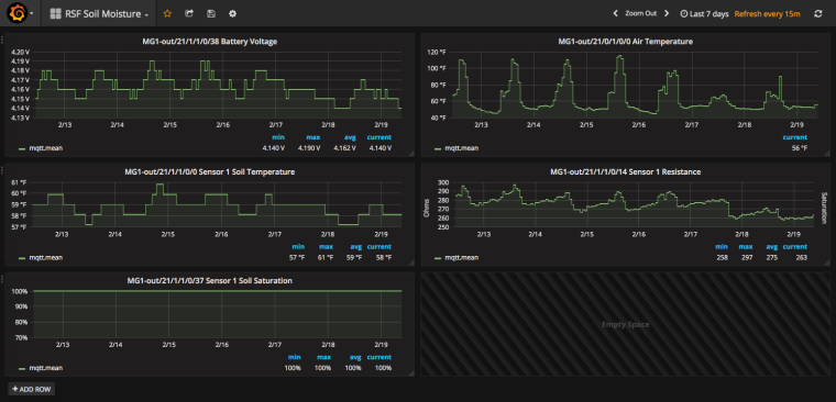
Heavy rain lately, so soil is at 100% saturation...
This was developed with MySensor 2.1.1 https://www.mysensors.org/
IDE 1.81
SAMD 1.6.11
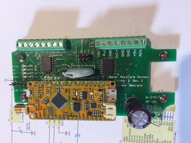
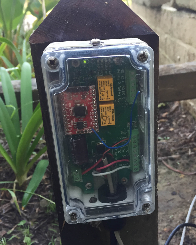
RocketScream M0 with RFM95 radio
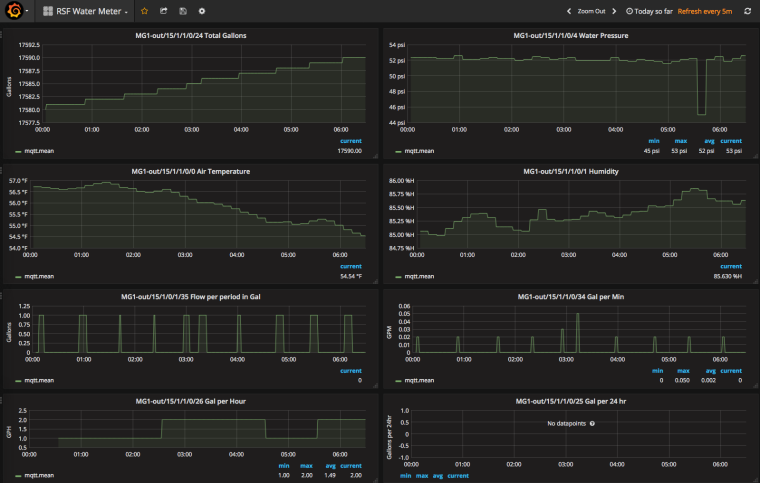
Data from the sensor to MQTT-gateway to MQTT to (Telegraf to InFluxdb to Grafana)
Controller function via NODE.RED connected via MQTT.
It measures soil moisture from 1 to 4 sensors, has options for soil and air temperature.
Support MCP9800 or Si7021 (humidity also) or temp sensor in DS3231 for air temp
DS18B20 for soil temp
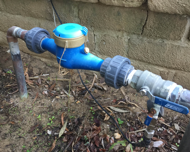
Support of a water pressure sensor via an analog port
Has a DS3231 Real Time clock to wake up processor at designated hour
Has support on the board for a flow meter and pressure sensor (but no software in this code base)
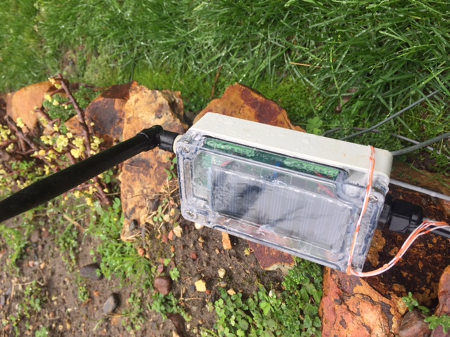
Solar, battery Powered or via 8 to 28v AC or DC
Sleep's most of the time and just wakes up to see if its time to send a report.
Support for requesting and receiving time of day for setting RTC
Support for updating sensor tx schedule via V_VAR1
(Board is designed to fit in a Hammond 1554 case)
https://github.com/trlafleur/Soil_Moisture_Sensor_MS_R1.1-RFM95
http://www.rocketscream.com/blog/product/mini-ultra-pro-with-radio/
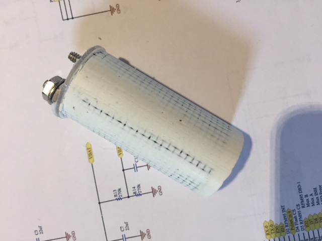
Sensor are made from plaster of paris (gypsum)
http://vanderleevineyard.com/1/post/2012/07/the-vinduino-project-2-making-and-installing-gypsum-soil-moisture-sensors.html

http://www.irrometer.com/sensors.html#wm

https://www.amazon.com/Delmhorst-GB-1-Gypsum-Sensor-Moisture/dp/B0002IKRUS (pkg of 10 each)
Based on the work of: Reinier van der Lee, www.vanderleevineyard.com