Navigation

    • Register
    • Login
    • OpenHardware.io
    • Categories
    • Recent
    • Tags
    • Popular
    1. Home
    2. lafleur
    3. Posts
    • Profile
    • Following
    • Followers
    • Topics
    • Posts
    • Best
    • Groups

    Posts made by lafleur

    • RE: VL53L0X with water tanks

      @Papari-Das

      See my documentation here for what I did for fuel oil, all will be applicable to water..

      https://github.com/trlafleur/Tasmota-Tank-Sensor

      posted in Troubleshooting
      lafleur
      lafleur
    • RE: Ultrasonic sensor JSN-SR04T

      To provide a large enough pulse to drive the ceramic transducer , you need a lot of energy, so they pump up the 5v with an inductor/transformer to provide a high voltage pulse. This is 60v or more…
      The more Energy you produce the farther the pulse will travel….

      Everything thing else on the board run at 3.3 to 5V.

      Add a large Capacitor of 100 µF are so between the 5v and ground on the device, this may clean up your problem.. Some CPU modules just can’t supply enough current quick enough that’s needed when the pulse is triggered.

      These are very inexpensive device, we’re luck to see them work at 1/2 the spec range.

      posted in Hardware
      lafleur
      lafleur
    • RE: 💬 STM32 Sensor Node

      It would be nice if you could post a .pdf of the schematic.... not everyone has the tool to see the board from the .sch file.

      posted in OpenHardware.io
      lafleur
      lafleur
    • RE: 8Bit or 32Bit processors

      @Nca78

      1.27mm headers 5x2 (.05in) Mouser 855-M50-3500542 made by Harwin

      posted in Hardware
      lafleur
      lafleur
    • RE: 💬 Sensebender Micro mk2

      Well, that news to me. I've always use the HCW variant and did NOT noticed the pin change. My error for not looking at the detail... (This was not the case with the RFM69W and HW radios, both shared the same pin-out)

      but again, using the HCW allow one to also use the RFM95 radios, and if you keep power below +13, power consumption is about the same... also the new RFM69 radio driver in 2.2b use adaptive power control as an option, this keep power use to a minimum saving power.

      I just re-checked the data sheets, RFM95 and RFM69HCW do share the same pin-out.

      posted in OpenHardware.io
      lafleur
      lafleur
    • RE: 💬 Sensebender Micro mk2

      Yes, The H = High Power version, C = Compact version 16x16mm pkg, vis 16x19mm pkg

      My error, RFM69CW and RFM69HCW are available, also note that if you do not use the power over +13dbm, power consumption is about the same between the radios.

      https://lowpowerlab.com/forum/rf-range-antennas-rfm69-library/rfm69w-and-rfm69hw-current-consumption/
      
      
      [0_1496604219131_RFM69CW-V1.1.pdf](/assets/uploads/files/1496604221362-rfm69cw-v1.1.pdf) 
      
      
      posted in OpenHardware.io
      lafleur
      lafleur
    • RE: 💬 Sensebender Micro mk2

      Both the RFM69HC and RFM69HCW are available in the smaller package.... again, this would allow RFM95 to be used.

      Thanks...

      [0_1496601875842_RFM69HC_DataSheet_v1.1.pdf](/assets/uploads/files/1496601877634-rfm69hc_datasheet_v1.1.pdf) 
      
      
      posted in OpenHardware.io
      lafleur
      lafleur
    • RE: 💬 Sensebender Micro mk2

      Is this board using the RFM69HCW footprint so that one could also use an RFM95??
      If not, please consider this change and you might want to consider as an option for DIO-1 connected to an I/O pin on the CPU.. (this would also make it compatible with LoRaWan network)

      Thanks

      posted in OpenHardware.io
      lafleur
      lafleur
    • RE: 8Bit or 32Bit processors

      I use the standard Arduino IDE for most things but moving to PlatformIO as it's editor is so much better that the brain dead one in the Arduino IDE

      posted in Hardware
      lafleur
      lafleur
    • RE: 8Bit or 32Bit processors

      @gohan Pro-mini, is a great part, but sometime you need a lot more! 32 bit is the future for me, less power, less cost, more resources....less hassles...

      posted in Hardware
      lafleur
      lafleur
    • RE: 8Bit or 32Bit processors

      @lafleur

      You should also add this to your test code to see debug messages from the MySensor stack.. Also add to gateway, so that you can see what happening on both ends....

      /*  Enable debug prints to serial monitor on port 0 */
      #define MY_DEBUG            // used by MySensor
      #define MY_DEBUG_VERBOSE_RFM69 
      
      posted in Hardware
      lafleur
      lafleur
    • RE: 8Bit or 32Bit processors

      @Nca78

      As manufacturing of chips goes to smaller and smaller die size, chip cost go down and preformance goes up..... older processors cost more to build that newer parts!

      It all means better performance, less power and more features for less money...

      The intel 8080 when it was introduced was $360, power hungry, no ram, no storage, no I/O, needed a lot of support chips.... we have come a long way!!!!

      posted in Hardware
      lafleur
      lafleur
    • RE: 8Bit or 32Bit processors

      The M0 chip cost less that the 8bit 328, so building your own boards, it cost less...

      Then you need to add a radio, $2 to $9. Crystal, $.50, connectors, flash, voltage regulators, leds, capacitors, resistors, pcb board.... ect, all add cost....

      But vendors building board, need to make a profit to stay alive, so you pay for their work....

      So yes, finish boards in small quantity cost $20 to $40 or so.... not a bad price for what you get.....

      posted in Hardware
      lafleur
      lafleur
    • RE: 8Bit or 32Bit processors

      @Sweeman

      I'm on travel, and do not have any hardware to test with...

      some notes:

      Use generic M0 processor definition tool-->board--> Arduino zero (native USB port)

      If I remember, 2.1.1 has NOT yet implemented sleep for M0 processors

      Here is a striped down version of your code.... get it to work first sending messages to your gateway, then start adding your real code back.... This complies, but I DID NOT HAVE ANY HW to test it on...

      Make sure you check the radio pins on the feather and that they are correct.

          /**
           * The MySensors Arduino library handles the wireless radio link and protocol
           * between your home built sensors/actuators and HA controller of choice.
           * The sensors forms a self healing radio network with optional repeaters. Each
           * repeater and gateway builds a routing tables in EEPROM which keeps track of the
           * network topology allowing messages to be routed to nodes.
           *
           * Created by Henrik Ekblad <henrik.ekblad@mysensors.org>
           * Copyright (C) 2013-2015 Sensnology AB
           * Full contributor list: https://github.com/mysensors/Arduino/graphs/contributors
           *
           * Documentation: http://www.mysensors.org
           * Support Forum: http://forum.mysensors.org
           *
           * This program is free software; you can redistribute it and/or
           * modify it under the terms of the GNU General Public License
           * version 2 as published by the Free Software Foundation.
           *
           *******************************
           *
           * DESCRIPTION
           *
           * Example sketch showing how to send in DS1820B OneWire temperature readings back to the controller
           * http://www.mysensors.org/build/temp
           */
      
      
          // Enable debug prints to serial monitor
          //#define MY_DEBUG 
      
          // Enable and select radio type attached
          //#define MY_RADIO_NRF24
          #define MY_RADIO_RFM69
      
          #include <SPI.h>
          #include <MySensors.h>  
      
      
      unsigned long SEND_FREQUENCY        = 10000;      // Minimum time between send (in milliseconds). We don't want to spam the gateway.
      unsigned long currentTime         = 0;
      unsigned long lastSendTime        = 0;
      unsigned long keepaliveTime       = 0;


          #define MY_RF69_SPI_CS 8
          #define MY_RF69_IRQ_PIN 7
          #define MY_RF69_IRQ_NUM 4
      
          // Initialize temperature message
          MyMessage msg(0,V_TEMP);
          
      
      /* ******************************************** */
          void before()
          {
           
          }
          
      
      /* ******************************************** */
          void setup()  
          { 
       
          }
      
      
      /* ******************************************** */
          void presentation() {
            // Send the sketch version information to the gateway and Controller
            sendSketchInfo("Temperature Sensor", "1.1");
            //present(0, S_TEMP);
            }
      
      
      /* ******************************************** */
          void loop()     
      { 
      
          currentTime = millis();                                    
      
       /* ***************** Send Sensor Data ***************** */
      
          if (currentTime - lastSendTime >= SEND_FREQUENCY)          // Only send values at a maximum rate
          {
            Serial.println("*** Sending Sensor Data"); 
      
           lastSendTime = currentTime;
      
          // lets send some data
            float temperature = 67.4;
             // Send in the new temperature
            send(msg.setSensor(0).set(temperature,1));
          }  // end of if
      
      } // end of loop


      posted in Hardware
      lafleur
      lafleur
    • RE: Trace to antenna?

      These are a good starting point...

      http://pdfserv.maximintegrated.com/en/an/AN2093.pdf
      http://www.analog.com/media/en/training-seminars/tutorials/MT-094.pdf

      Yes, it all maters, having 50 ohms from the radio to the antenna will lower the VSWR and make transfer of more power to the antenna.

      posted in Hardware
      lafleur
      lafleur
    • 8Bit or 32Bit processors

      A number of people have ask me about why I'm using 32bit processors when an 8bit will do. Well its simple, for small development projects of less that a few hundreds unit, the larger flash, larger ram, faster CPU, lower power devices, and cheaper raw devices, allow for faster code development... no time wasted on how to save flash or ram space.. seldom having to concern myself about CPU speed.

      If I'm doing a project that requires very large volume, or special needs, I will again consider an 8 or 16bit processor, but again, these days often the 32bit devices are cheaper and more functional.

      Below are a number of CPU boards with RFM69 or RFM95 Radios attach that can be used with MySensor.

      In MySensor space, for my projects, my favorite 32bit processor board is:
      RocketScream M0 ultra pro Ver2, RFM69 or RFM95 radio, battery connector/charger, USB port, EUI64 chip, large external flash, very low power, u.FL or SMA connector, great support...
      http://www.rocketscream.com/blog/product/mini-ultra-pro-v2-with-radio/

      Other 32 Bit:
      Adafruit Feather LoRa M0, NO EUI64, No External flash, battery connector
      https://www.adafruit.com/product/3178 RFM95
      https://www.adafruit.com/product/3176 RFM69

      Non 32 bit processors:
      MoteinoMega LoRa, ATmega1284P, RFM69 or RFM95, EUI64 chip, large external flash, u.FL or SMA connector
      https://lowpowerlab.com/shop/product/119

      Moteino LoRa, ATmega328P, RFM69 or RFM95, large external flash, NO EUI64 chip
      https://lowpowerlab.com/shop/product/99

      Adafruit Feather LoRa, ATmega32U4 CPU, NO EUI64, No External flash, battery connector, RFM69 or RFM95
      https://www.adafruit.com/product/3078

      posted in Hardware
      lafleur
      lafleur
    • New high power variant of the RFM95 --> RFM95PW +30dBm

      HopeRF has started selling a 1watt, +30dBm, version of the LoRa RFM95 radio. Aliexpress has them at $120/5.

      The pin-out is the same, except for the 3.3v input pin is now VCC (5 to 6.4v) and pin 9, was GND now 3.3v out.

      Width is 18mm vers 16mm on the old part, length is 35.4mm. Pin spacing is the same at 2mm.
      Power requirements are ~700ma at TX, 15ma RX.
      Their are no register changes... Its just a power amp on the basic RFM95.

      http://www.hoperf.com/rf_transceiver/Enhanced_Power/RFM95PW.htm

      In my testing on a farm to measure soil moisture, water level and gate status, where the gateway is over 2.5 mi away, their performance has been excellent.... Radios have a 3dBi antenna, gateway has a 6dBi antenna.

      They are connected with a 5 watt solar panel and a 6000ma battery, it my test with no solar panel connected for 7 days, battery is only down 3%, they report back 24 time a day.

      So yes, it nice to have an option of a +30dBi radio... they do work!

      posted in Hardware
      lafleur
      lafleur
    • RE: Sensor IDs, best practices?

      I solved the issue by using extra I/O pins and assign a static node address from a base address + ID bits... In my case below, I used 3 ID pin's.

      /* **************************************************************************** */
      /*                                Before                                        */
      /* **************************************************************************** */
      
       // Before is part of MySensor core 
      void before() 
      { 
      
       
       // need to set up pins prior to reading them...
           pinMode(ID0, INPUT_PULLUP);
           pinMode(ID1, INPUT_PULLUP);
           pinMode(ID2, INPUT_PULLUP);
           
           myNodeID  = !digitalRead (ID0);                     // ID bit are 0 = on, so we invert them
           myNodeID |= (!digitalRead(ID1) << 1);           
           myNodeID |= (!digitalRead(ID2) << 2);
      
           myNodeID += NodeID_Base;                            // set our node ID
      
           // We no longer need these pins, so remove pullups to save power
           pinMode(ID0, INPUT);
           pinMode(ID1, INPUT);
           pinMode(ID2, INPUT);
      }
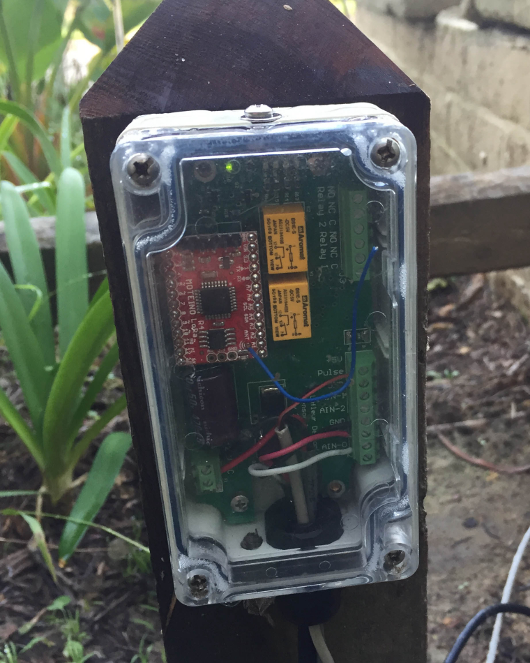
      
      
      posted in Development
      lafleur
      lafleur
    • Water flow and pressure Sensor

      WaterMeter-MS-3.0i-RFM95

      Data from the MySensor node to MQTT-gateway to MQTT to Telegraf to InFluxdb to Grafana.
      Controller function via NODE.RED connected via MQTT.

      0_1488549650584_Screen Shot 2017-02-21 at 6.29.37 AM.png

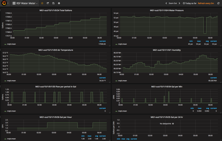
      It measures water flow from a Dwyer WMT2 water meter in pulse per gallon.

      Used a 0 to 100PSI pressure sensor (from ebay), via an analog port.

      Support MCP9800 or Si7021 (humidity also) for air temp.

      Two relay outputs

      3 Analog inputs

      MAX6816 or analog filter for contact de-bouncing for water meter

      Powered via an 8 to 28v AC or DC external power source

      (Board is designed to fit in a Hammond 1554 case)

      Processor is a Moteino R4 LoRa with a RFM95

      Sends:

      • Gal per minutes
      • Gal per hour
      • Gal per day
      • Gal of current flow
      • Total gallons
      • Air Temperature
      • Humidity
      • Water pressure
      • Excessive Flow Message

      https://www.dwyer-inst.com/Product/Flow/WaterMeters/SeriesWMT2

      https://lowpowerlab.com/shop/product/99

      design file are located at:

      https://github.com/trlafleur/WaterMeter-MS-3.0i-RFM95
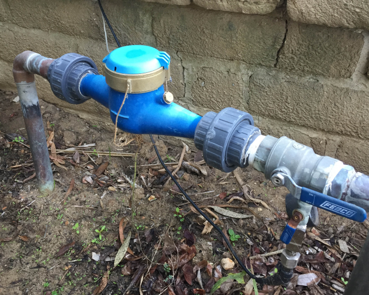
      

      1_1488551446939_IMG_5072a.jpg 0_1488551446939_IMG_5073a.jpg

      posted in My Project
      lafleur
      lafleur
    • RE: RFM95 Sleep Mode

      @lafleur

      I have been using the transportinit() and transportpowerdown(), as suggested and it has been working fine if I was just sending data...

      But when I needed to receive data from the controller, I was never receiving any data from the controller, even if I allowed a RX window of 20 sec or more.

      On Wake up, If I remove the call to transportinit(), all work fine again... TX and RX work just fine...

      What going on here?? Why is system working without the need to call transportinit() as you suggested.

      using a SAMD processor M0
      IDE 1.8.1
      MySensor 2.1.1

      My current code base:

      https://github.com/trlafleur/Soil_Moisture_Sensor_MS_R1.1-RFM95
      
      /* **************** System Sleep ******************* */
      void systemSleep()
      {
          debug1(PSTR("\n*** Going to Sleep ***\n"));
          wait (100);
          // put led's, radio and flash to sleep
          // Turn off LED's
          // Put Flash to sleep
          // Put Radio and transport to Sleep
          transportPowerDown();              // Shut down radio and MySensor transport
          
          interrupts();                      // make sure interrupts are on...
          LowPower.standby();                // SAMD sleep from LowPower systems
          
             //  .... we will wake up from sleeping here if triggered from an interrupt
          interrupts();                       // make sure interrupts are on...                                      
      }
      
      /* **************** System Wake-up from Sleep ******************* */
      void systemWakeUp() 
      {                                          
          
          //  re enable LED's if needed
          // wake up Flash if needed
      
          // wake up MySensor transport and Radio from Sleep
          //transportInit();
                                    // as MySensor had NO sleep or Watch Dog for SAMD, this will
                                              // wake us up so that we can send and receive messages
          while (!isTransportReady()) {       // Make sure transport is ready
          _process(); 
          interrupts();                       // make sure interrupts are on...
      }
      
      posted in Development
      lafleur
      lafleur
    • Dragnio LG01 LoRa gateway

      Anyone had a chance to test or port MySensor code to this device? $56

      https://www.tindie.com/products/edwin/lg01-lora-openwrt-iot-gateway/

      posted in General Discussion
      lafleur
      lafleur
    • Multi-sensor soil moisture node

      This is a work in progress! , but most everything works.

      0_1487524799943_Screen Shot 2017-02-19 at 9.17.43 AM.png

      Heavy rain lately, so soil is at 100% saturation...

      This was developed with MySensor 2.1.1  https://www.mysensors.org/
      IDE 1.81
      SAMD 1.6.11
      RocketScream M0 with RFM95 radio
      

      Data from the sensor to MQTT-gateway to MQTT to (Telegraf to InFluxdb to Grafana)
      Controller function via NODE.RED connected via MQTT.

      It measures soil moisture from 1 to 4 sensors, has options for soil and air temperature.
      Support MCP9800 or Si7021 (humidity also) or temp sensor in DS3231 for air temp
      DS18B20 for soil temp
      Support of a water pressure sensor via an analog port
      Has a DS3231 Real Time clock to wake up processor at designated hour
      Has support on the board for a flow meter and pressure sensor (but no software in this code base)
      Solar, battery Powered or via 8 to 28v AC or DC
      Sleep's most of the time and just wakes up to see if its time to send a report.
      Support for requesting and receiving time of day for setting RTC
      Support for updating sensor tx schedule via V_VAR1
      (Board is designed to fit in a Hammond 1554 case)

      https://github.com/trlafleur/Soil_Moisture_Sensor_MS_R1.1-RFM95

      http://www.rocketscream.com/blog/product/mini-ultra-pro-with-radio/

      Sensor are made from plaster of paris (gypsum)

      http://vanderleevineyard.com/1/post/2012/07/the-vinduino-project-2-making-and-installing-gypsum-soil-moisture-sensors.html
      http://www.irrometer.com/sensors.html#wm
      https://www.amazon.com/Delmhorst-GB-1-Gypsum-Sensor-Moisture/dp/B0002IKRUS (pkg of 10 each)

      Based on the work of: Reinier van der Lee, www.vanderleevineyard.com

      0_1487526137636_IMG_5178.JPG 0_1487526144517_IMG_5177.JPG 0_1487526150950_IMG_5308.JPG

      posted in My Project
      lafleur
      lafleur
    • RE: Sending Time to a Node

      I doing some gateway/controller code.... looks like I got it to work...

      I was assuming that a broadcast was used to return the time... but its NOT, its specific to each node...

      Suggestion...

      Allow time to be sent as a broadcast message, this will allow all node to receive time without having to wait to make or received a specific request

      posted in Development
      lafleur
      lafleur
    • Sending Time to a Node

      What is the exact format of a message to send time to a node??

      Thanks

      These are NOT working for me...

      /1/255/3/0/1/123456 
      /255/22/3/0/1/123456
      /1/22/3/0/1/123456
      /0/255/3/0/1/123456  
      
      posted in Development
      lafleur
      lafleur
    • RFM95 Soil Moisture Sensor

      This is a work in progress! , but most everything works.

      It measures soil moisture from 1 to 4 sensors, has options for soil and air temperature.
      Support MCP9800 or Si7021 (humidity also) or Temp sensor in DS3231 for air temp
      DS18B20 for soil temp
      Support of a water pressure sensor via an analog port
      Has a DS3231 Real Time clock to wake up processor at designated hour
      Has support on the board for a flow meter (but no software in this code base)
      Uses a RocketScream Mini-Pro M0 CPU with an RFM95 radio
      Solar, battery Powered or via 8 to 28v AC or DC
      Sleep's most of the time and just wakes up to see if its time to send a report.
      (Board is designed to fit in a Hammond 1554 case)

      https://github.com/trlafleur/Soil_Moisture_Sensor_MS_R1.1-RFM95
      

      Sensor are made from plaster of paris (gypsum)

      http://vanderleevineyard.com/1/post/2012/07/the-vinduino-project-2-making-and-installing-gypsum-soil-moisture-sensors.html
      
      http://www.irrometer.com/sensors.html#wm
      
      https://www.amazon.com/Delmhorst-GB-1-Gypsum-Sensor-Moisture/dp/B0002IKRUS
      

      Based on the work of: Reinier van der Lee, www.vanderleevineyard.com

      posted in Development
      lafleur
      lafleur
    • RE: RFM95 Sleep Mode

      Thanks...

      I'm using RocketStream lib. LowPower sleep for now...

      when I wake up, I get some messages from the TSF, not sure what they are telling me...
      it appear to not like the message it received...

      My Current Code....

      https://github.com/trlafleur/Soil_Moisture_Sensor_MS_R1.1-RFM95
      

      thanks

      *** Going to Sleep ***
      *** Wakeing From Sleep at: 17:11
      TSF:MSG:READ,0-0-76,s=255,c=3,t=0,pt=1,l=4,sg=1:1
      !TSF:MSG:LEN,4!=32
      TSF:MSG:READ,0-1-76,s=255,c=3,t=0,pt=1,l=5,sg=0:1
      !TSF:MSG:LEN,4!=12
      TSF:MSG:READ,0-2-75,s=255,c=3,t=0,pt=1,l=4,sg=1:1
      !TSF:MSG:LEN,4!=32
      TSF:MSG:READ,0-3-76,s=255,c=3,t=0,pt=1,l=4,sg=1:1
      !TSF:MSG:LEN,4!=32
      TSF:MSG:READ,0-4-75,s=255,c=3,t=0,pt=1,l=4,sg=1:1
      !TSF:MSG:LEN,4!=32
      TSF:MSG:READ,0-5-75,s=255,c=3,t=0,pt=1,l=4,sg=1:1
      !TSF:MSG:LEN,4!=32
      TSF:MSG:READ,0-6-75,s=255,c=3,t=0,pt=1,l=4,sg=1:1
      !TSF:MSG:LEN,4!=32
      TSF:MSG:READ,0-7-75,s=255,c=3,t=0,pt=1,l=4,sg=1:1
      !TSF:MSG:LEN,4!=32
      TSF:MSG:READ,0-9-76,s=255,c=3,t=0,pt=1,l=5,sg=0:1
      !TSF:MSG:LEN,4!=12
      TSF:MSG:READ,0-10-75,s=255,c=3,t=0,pt=1,l=5,sg=0:1
      !TSF:MSG:LEN,4!=12
      *** Going to Sleep ***
      
      posted in Development
      lafleur
      lafleur
    • RE: RFM95 Sleep Mode

      As the sleep function are NOT implemented yet for the M0 SAMD processor in MyHwSAMD.ccp, is using transportinit and transportpowerdown the proper way to allow the core to shut down the radio to sleep and re awake??

      I ask because I do not see this being done in the MyHwATMega328.cpp sleep functions...

      My goal it to cut power down to a minimum with the M0 processor ...

      posted in Development
      lafleur
      lafleur
    • RFM95 Sleep Mode

      I noticed that the RFM95 driver has function to put the radio to sleep...
      do I need to check anything else prior to the call?

      LOCAL bool RFM95_sleep(void);
      

      what is required to re-awake the radio after this function is called...
      do I just set the mode back to RX or Standby?
      Any delays needed to awake the radio?

      also, why is it tagged as LOCAL? is it not intended to be used in project code??

      Using an M0 processor 2.1 code base

      Thanks

      posted in Development
      lafleur
      lafleur
    • RE: Default debug serial port

      @tbowmo thanks... works just as expected.....

      posted in Feature Requests
      lafleur
      lafleur
    • RE: Excessive NACK

      Gateway is ESP8266 and radio is RFM95

      posted in Development
      lafleur
      lafleur
    • Excessive NACK

      If I set the ACK flag in my send() , I get a lot of NACK from the MQTT gateway..

      MySensor 2.1b
      M0 CPU
      IDE 1.6.13

      1. Will MySensor do the auto re-transmit? if not, why not?, it should up to N times.
      2. If I run without the ACK flag set, I get very few if any NACK
      3. If I add a 500ms delay after each send, the number of NACK is less, (but this is a waist of power)
      4. all board have 47uf at the radio
      TSM:INIT
      TSF:WUR:MS=0
      TSM:INIT:TSP OK
      TSM:INIT:STATID=20
      TSF:SID:OK,ID=20
      TSM:FPAR
      TSF:MSG:SEND,20-20-255-255,s=255,c=3,t=7,pt=0,l=0,sg=0,ft=0,st=OK:
      TSF:MSG:READ,0-0-20,s=255,c=3,t=8,pt=1,l=1,sg=0:0
      TSF:MSG:FPAR PREF
      TSF:MSG:FPAR OK,ID=0,D=1
      TSM:FPAR:OK
      TSM:ID
      TSM:ID:OK
      TSM:UPL
      TSF:MSG:SEND,20-20-0-0,s=255,c=3,t=24,pt=1,l=1,sg=0,ft=0,st=OK:1
      TSF:MSG:READ,0-0-20,s=255,c=3,t=25,pt=1,l=1,sg=0:1
      TSF:MSG:PONG RECV,HP=1
      TSM:UPL:OK
      TSM:READY:ID=20,PAR=0,DIS=1
      TSF:MSG:SEND,20-20-0-0,s=255,c=3,t=15,pt=6,l=2,sg=0,ft=0,st=OK:0100
      TSF:MSG:READ,0-0-20,s=255,c=3,t=15,pt=6,l=2,sg=0:0100
      TSF:MSG:SEND,20-20-0-0,s=255,c=0,t=17,pt=0,l=10,sg=0,ft=0,st=OK:2.1.0-beta
      TSF:MSG:SEND,20-20-0-0,s=255,c=3,t=6,pt=1,l=1,sg=0,ft=0,st=OK:0
      TSF:MSG:SEND,20-20-0-0,s=255,c=3,t=11,pt=0,l=20,sg=0,ft=0,st=OK:Soil Moisture Sensor
      !TSF:MSG:SEND,20-20-0-0,s=255,c=3,t=12,pt=0,l=4,sg=0,ft=0,st=NACK:1.1a
      TSF:MSG:SEND,20-20-0-0,s=1,c=0,t=21,pt=0,l=14,sg=0,ft=1,st=OK:Water Moisture
      MCO:REG:REQ
      !TSF:MSG:SEND,20-20-0-0,s=255,c=3,t=26,pt=1,l=1,sg=0,ft=0,st=NACK:2
      TSF:MSG:SEND,20-20-0-0,s=255,c=3,t=26,pt=1,l=1,sg=0,ft=1,st=OK:2
      TSF:MSG:READ,0-0-20,s=255,c=3,t=27,pt=1,l=1,sg=0:1
      MCO:PIM:NODE REG=1
      MCO:BGN:STP
      TSF:MSG:SEND,20-20-0-0,s=1,c=1,t=47,pt=0,l=8,sg=0,ft=0,st=OK:Starting
      ***In Setup
       ** Hello from the Water Sensor on a M0 **
       Soil Moisture Sensor 1.1a
       /Users/lafleur/Desktop/MySensor-Arduino-development/Arduino_fork/Soil_Moisture_Sensor_R1.1-RFM95/Soil_Moisture_Sensor_ Dec 28 2016, 10:12:32 
      
       My Node ID: 20
      
      Setting Time on DS3231 
      MCO:BGN:INIT OK,TSP=1
      TSF:MSG:READ,0-0-20,s=1,c=1,t=47,pt=0,l=8,sg=0:Starting
      TSF:MSG:ACK
      Moisture 1: 13 Res: 10100
      TSF:MSG:SEND,20-20-0-0,s=1,c=1,t=27,pt=4,l=4,sg=0,ft=0,st=OK:13
      !TSF:MSG:SEND,20-20-0-0,s=1,c=1,t=14,pt=5,l=4,sg=0,ft=0,st=NACK:10100
      Moisture 2: 3 Res: 100000
      TSF:MSG:SEND,20-20-0-0,s=2,c=1,t=27,pt=4,l=4,sg=0,ft=1,st=OK:3
      !TSF:MSG:SEND,20-20-0-0,s=2,c=1,t=14,pt=5,l=4,sg=0,ft=0,st=NACK:100000
      Moisture 3: 3 Res: 100000
      TSF:MSG:SEND,20-20-0-0,s=3,c=1,t=27,pt=4,l=4,sg=0,ft=1,st=OK:3
      !TSF:MSG:SEND,20-20-0-0,s=3,c=1,t=14,pt=5,l=4,sg=0,ft=0,st=NACK:100000
      Moisture 4: 3 Res: 100000
      TSF:MSG:SEND,20-20-0-0,s=4,c=1,t=27,pt=4,l=4,sg=0,ft=1,st=OK:3
      !TSF:MSG:SEND,20-20-0-0,s=4,c=1,t=14,pt=5,l=4,sg=0,ft=0,st=NACK:100000
      TSF:MSG:SEND,20-20-0-0,s=1,c=1,t=38,pt=7,l=5,sg=0,ft=1,st=OK:4.25
      !TSF:MSG:SEND,20-20-0-0,s=255,c=3,t=0,pt=1,l=1,sg=0,ft=0,st=NACK:65
      Vbat: 4.25V 
      Moisture 1: 13 Res: 10102
      TSF:MSG:SEND,20-20-0-0,s=1,c=1,t=27,pt=4,l=4,sg=0,ft=1,st=OK:13
      !TSF:MSG:SEND,20-20-0-0,s=1,c=1,t=14,pt=5,l=4,sg=0,ft=0,st=NACK:10102
      Moisture 2: 3 Res: 100000
      TSF:MSG:SEND,20-20-0-0,s=2,c=1,t=27,pt=4,l=4,sg=0,ft=1,st=OK:3
      !TSF:MSG:SEND,20-20-0-0,s=2,c=1,t=14,pt=5,l=4,sg=0,ft=0,st=NACK:100000
      Moisture 3: 3 Res: 100000
      TSF:MSG:SEND,20-20-0-0,s=3,c=1,t=27,pt=4,l=4,sg=0,ft=1,st=OK:3
      !TSF:MSG:SEND,20-20-0-0,s=3,c=1,t=14,pt=5,l=4,sg=0,ft=0,st=NACK:100000
      Moisture 4: 3 Res: 100000
      TSF:MSG:SEND,20-20-0-0,s=4,c=1,t=27,pt=4,l=4,sg=0,ft=1,st=OK:3
      !TSF:MSG:SEND,20-20-0-0,s=4,c=1,t=14,pt=5,l=4,sg=0,ft=0,st=NACK:100000
      TSF:MSG:SEND,20-20-0-0,s=1,c=1,t=38,pt=7,l=5,sg=0,ft=1,st=OK:4.26
      !TSF:MSG:SEND,20-20-0-0,s=255,c=3,t=0,pt=1,l=1,sg=0,ft=0,st=NACK:65
      Vbat: 4.25V 
      
      posted in Development
      lafleur
      lafleur
    • RE: Default debug serial port

      Thanks... Unclear on why I did not see that when I looks for something like that...

      Made these changes... added issue 707 to development branch

      from:

      #define MY_SERIALDEVICE SerialUSB
      

      to:

      #ifndef MY_SERIALDEVICE
      #define MY_SERIALDEVICE SerialUSB
      #endif
      
      posted in Feature Requests
      lafleur
      lafleur
    • RE: RFM69 RSSI value report

      RSSI......

      posted in Feature Requests
      lafleur
      lafleur
    • Default debug serial port

      Is there a way to change the debug serial port in 2.1b code?

      In using a ARM M0, the serial port defaults to the USB port... I would like to reroute to Serial or Serial1

      Thanks

      posted in Feature Requests
      lafleur
      lafleur
    • RE: RFM69 RSSI value report

      Great work, would like to see this added to RFM95 radio code...

      posted in Feature Requests
      lafleur
      lafleur
    • ESP8266 failing with pm open,type:2 0

      The GW has been working just fine for that last few days, but when I rebooted it today, I now get the "pm open,type:2 0" from the ESP8266. When this happen, the GW stops working... Re building and loading of new code has same problem.
      I have tried 3 different ESP8266

      Any ideas on what is the root cause??

      Thanks

      GatewayESP8266MQTTClient with RFM95 radio
      Using beta 2.1. as of 1Dec2016
      IDE 1.6.13
      esp8266/hardware/esp8266/2.3.0

      
      0;255;3;0;9;MCO:BGN:INIT GW,CP=RLNGE--,VER=2.1.0-beta
      0;255;3;0;9;TSF:LRT:OK
      0;255;3;0;9;TSM:INIT
      0;255;3;0;9;TSF:WUR:MS=0
      0;255;3;0;9;!TSM:INIT:TSP FAIL
      0;255;3;0;9;TSM:FAIL:CNT=1
      0;255;3;0;9;TSM:FAIL:PDT
      scandone
      state: 0 -> 2 (b0)
      state: 2 -> 3 (0)
      state: 3 -> 5 (10)
      add 0
      aid 2
      cnt 
      
      connected with lafleur, channel 1
      dhcp client start...
      ip:192.94.167.240,mask:255.255.255.0,gw:192.94.167.4
      0;255;3;0;9;TSM:FAIL:RE-INIT
      0;255;3;0;9;TSM:INIT
      0;255;3;0;9;!TSM:INIT:TSP FAIL
      0;255;3;0;9;TSM:FAIL:CNT=2
      0;255;3;0;9;TSM:FAIL:PDT
      pm open,type:2 0       <-----------------------------
      0;255;3;0;9;TSM:FAIL:RE-INIT
      0;255;3;0;9;TSM:INIT
      0;255;3;0;9;!TSM:INIT:TSP FAIL
      0;255;3;0;9;TSM:FAIL:CNT=3
      0;255;3;0;9;TSM:FAIL:PDT
      0;255;3;0;9;TSM:FAIL:RE-INIT
      0;255;3;0;9;TSM:INIT
      
      
      /*
       * TRL Ver 1 01 Dec 2016
       * MySensor 2.1b as of 23 Nov 2016
       */
        
      #include <ESP8266WiFi.h>
      
      // Enable debug prints to serial monitor
      #define MY_DEBUG
      //#define MY_SPECIAL_DEBUG
      #define MY_DEBUG_VERBOSE_RFM95
      
      
      #if defined(ARDUINO_ARCH_ESP8266)
      #else
      #error This program requires an ESP8266 CPU
      #endif
      
      //#define MY_DEFAULT_RX_LED_PIN   16
      #define MY_DEFAULT_TX_LED_PIN     16
      //#define MY_DEFAULT_ERR_LED_PIN  26
      
      // Use a bit lower baudrate for serial prints on ESP8266 than default in MyConfig.h
      #define MY_BAUD_RATE 115200
      
      // Enables and select radio type (if attached)
      #define MY_RADIO_RFM95
      
      // Pin's defined below are for ESP8266
      #define MY_RFM95_MODEM_CONFIGRUATION RFM95_BW125CR45SF128
      //#define MY_RFM95_RST_PIN RFM95_RST_PIN
      #define MY_RFM95_IRQ_PIN                15
      #define MY_RFM95_SPI_CS                 2
      #define MY_RFM95_TX_POWER               23  // max is 23
      //#define MY_RFM95_ATC_MODE_DISABLED
      #define MY_RFM95_ATC_TARGET_RSSI        (-60)
      #define MY_RFM95_FREQUENCY              (915.0f)
      
      #define MY_GATEWAY_MQTT_CLIENT
      #define MY_GATEWAY_ESP8266
      
      // Set this node's subscribe and publish topic prefix
      #define MY_MQTT_PUBLISH_TOPIC_PREFIX   "MG1-out"
      #define MY_MQTT_SUBSCRIBE_TOPIC_PREFIX "MG1-in"
      
      // Set MQTT client id
      #define MY_MQTT_CLIENT_ID "mysensors-2"
      
      // Enable these if your MQTT broker requires usenrame/password
      //#define MY_MQTT_USER "username"
      //#define MY_MQTT_PASSWORD "password"
      
      // Set WIFI SSID and password
      #define MY_ESP8266_SSID "test"
      #define MY_ESP8266_PASSWORD ""
      
      // Set the hostname for the WiFi Client. This is the hostname
      // it will pass to the DHCP server if not static.
      // #define MY_ESP8266_HOSTNAME "mqtt-sensor-gateway"
      
      // Enable MY_IP_ADDRESS here if you want a static ip address (no DHCP)
      #define MY_IP_ADDRESS 192, 94, 167, 42
      
      // If using static ip you need to define Gateway and Subnet address as well
      #define MY_IP_GATEWAY_ADDRESS 192, 94, 167, 4
      #define MY_IP_SUBNET_ADDRESS 255,255,255,0
      
      // MQTT broker ip address.
      #define MY_CONTROLLER_IP_ADDRESS 192, 94, 167, 32
      
      // The MQTT broker port to to open
      #define MY_PORT 1883
      
      #define MY_PARENT_NODE_ID   0
      
       /*
      // Enable inclusion mode
      #define MY_INCLUSION_MODE_FEATURE
      // Enable Inclusion mode button on gateway
      #define MY_INCLUSION_BUTTON_FEATURE
      // Set inclusion mode duration (in seconds)
      #define MY_INCLUSION_MODE_DURATION 60
      // Digital pin used for inclusion mode button
      #define MY_INCLUSION_MODE_BUTTON_PIN  3
      
      // Set blinking period
      #define MY_DEFAULT_LED_BLINK_PERIOD 300
      
      // Flash leds on rx/tx/err
      #define MY_DEFAULT_ERR_LED_PIN 16  // Error led pin
      #define MY_DEFAULT_RX_LED_PIN  16  // Receive led pin
      #define MY_DEFAULT_TX_LED_PIN  16  // the PCB, on board LED
      */
      
      
      /* ************************************************************************************** */
      // All #define above need to be prior to #include <MySensors.h> below
      #include <MySensors.h>
      
      
       // this is part of MySensor core 
      void before() 
      { 
        Serial.println ("In before");
        //WiFi.mode(WIFI_AP);    // : set mode to WIFI_AP, WIFI_STA, or WIFI_AP_STA or WIFI_OFF
        //wifi_set_opmode_current(STATIONAP_MODE);
        //wifi_set_opmode_current(STATION_MODE);
       }
      
      void setup() 
      {
        Serial.println("In Setup");
        }
      
      void presentation() 
      {
        // Present locally attached sensors here
      }
      
      
      void loop() 
      {
        // Send locally attach sensors data here
      }
      
      
      posted in Development
      lafleur
      lafleur
    • RE: Changing Node ID at run time

      I have this working now, it was a setup issue on my part...

      #define MY_NODE_ID myNodeId
      
      
      int8_t myNodeId;
      
      #define MY_NODE_ID myNodeId
      
      void before () { 
          // read I/O pins and set myNodeId
          myNodeId = 32;
          Serial.println( myNodeId );
      }
      
      
      posted in Development
      lafleur
      lafleur
    • RE: Changing Node ID at run time

      @lafleur

      See issue #675 in Github...

      https://github.com/mysensors/MySensors/issues/675

      posted in Development
      lafleur
      lafleur
    • RE: Changing Node ID at run time

      Good idea, but it did not worked...

      The node was at 10, so I set the myNodeId = 12 in before() function, node continued to use ID of 10, most likely from Flash.... before() might be running prior to initialization of all variables...

      posted in Development
      lafleur
      lafleur
    • Changing Node ID at run time

      Is it possible to change the node ID at run time in Setup???

      ie: MY_NODE_ID

      The way it looks now, it needs to be set prior to Setup or Loop being invoked using a:

      #define MY_NODE_ID 10

      I'm using an MQTT GW and would like each device to get its ID from a jumper on the board...

      Thanks

      posted in Development
      lafleur
      lafleur
    • RE: MoteinoMEGA on 2.0.1 error compiling

      I'm using beta from Yesterday (23Nov2016), still an issue...

      Made these changes in: digitalWriteFast.h to get started as the 644 and 1284 have the same pinout.

      #elif defined(__AVR_ATmega644__) || defined(__AVR_ATmega644P__) || defined(__AVR_ATmega1284__) || defined(__AVR_ATmega1284P__)
      	#define __digitalPinToPortReg(__pin)	(((__pin) <= 7) ? &PORTB : (((__pin) >= 8 && (__pin) <= 15) ? &PORTD : (((__pin) >= 16 && (__pin) <= 23) ? &PORTC : &PORTA)))
      	#define __digitalPinToDDRReg(__pin)		(((__pin) <= 7) ? &DDRB : (((__pin) >= 8 && (__pin) <= 15) ? &DDRD : (((__pin) >= 8 && (__pin) <= 15) ? &DDRC : &DDRA)))
      	#define __digitalPinToPINReg(__pin)		(((__pin) <= 7) ? &PINB : (((__pin) >= 8 && (__pin) <= 15) ? &PIND : (((__pin) >= 8 && (__pin) <= 15) ? &PINC : &PINA)))
      	#define __digitalPinToBit(__pin)		(((__pin) <= 7) ? (__pin) : (((__pin) >= 8 && (__pin) <= 15) ? (__pin) - 8 : (((__pin) >= 16 && (__pin) <= 23) ? (__pin) - 16 : (__pin) - 24)))


      But now I get:

      "digitalPinToInterrupt" not defined

      This function seem to be defined for a RPI, but I'm using a MoteinoMEGA, so something is still wrong. I just deleted the function call for now. Not needed on Arduino.

      posted in Development
      lafleur
      lafleur
    • RE: MoteinoMEGA on 2.0.1 error compiling

      Anyone have a fix for this yet??

      Thanks

      posted in Development
      lafleur
      lafleur
    • RE: rfm69 and atc

      It's great to see that you got it all working from the PR440. I hope others will find your work useful....

      I'm my test,it works very well.....

      posted in Development
      lafleur
      lafleur
    • RE: rfm69 and atc

      I did exactly what you ask, but it continued to fail in building the examples... In another PR, you pointed out that there were issue in building the examples under IDE 1.6.9.

      My feeling were not hurt, but I did NOT want to wast anymore time in dealing with Jenkins with out guidance.... Also there is NO guide on what Jenkins expect to see in its development environment. it all trial and error...

      FYI... I have developed RFM95 and TTN transport layers for my snapshot of your code.

      posted in Development
      lafleur
      lafleur
    • RE: rfm69 and atc

      @frencho

      I have it all working, but my development environment and Jenkins are not in alignment, so my PR was rejected by the development team. They provide me NO help in resolving the issue... They tend to favor and support only the older NRF24L01 radio and have little interests in the newer, better preforming RFM69 or RFM95 radios. So have a look at my code changes in the close PR. It was not hard to implement. I have move on.....

      posted in Development
      lafleur
      lafleur
    • RE: Please add a guide for how to connect use the RFM69(H)W

      There might be, do a search for: "arduino software spi"

      Almost all chip supported by the Arduino IDE have one or more hardware SPI channels, each can be shared with multiple SPI devices connected to it with proper selection of the device CS line...

      So the need for a software SPI is rare...

      Good Luck...

      posted in Feature Requests
      lafleur
      lafleur
    • RE: Please add a guide for how to connect use the RFM69(H)W

      The pins for the SPI device is supplied by the SPI support library for the CPU device that you are using in the Arduino IDE library

      posted in Feature Requests
      lafleur
      lafleur
    • RE: Please add a guide for how to connect use the RFM69(H)W

      The SPI connections are hardware SPI in the chip, not a softSPI.. (may work, but I have not tested)

      If you look at the data sheet and schematics for the Mega, you see that the SPI pins are very well documented.....

      http://lowpowerlab.com/blog/2014/08/09/moteinomega-available-now/

      https://github.com/LowPowerLab/Moteino/blob/master/MEGA/MoteinoMEGA_Schematic.pdf

      Pins 7-6--5-4 are the four standard SPI pins, SCK, MISO, MOSI, SS, pin D2 is use as the interrupt from DIO0 on the radio... Look at the schematic and you see the correct pin-out from the radio to the processor... You will note the swap in MISO and MOSI pins. In on the CPU is out on the radio.. ect...
      CPU RFM69
      4 NSS
      5 MOSI
      6 MISO
      7 SCK
      2 DIO0

      In my main code I use these defines... not in the config.h file... ( you could put them there also)
      I'm using ver 2.0 code base, NOT 1.4 or 1.5

      #ifdef __AVR_ATmega1284P__        // use for Moteino Mega Note: LED on Mega are 1 = on, 0 = off
      // MoteinoMEGA
      #define MY_RF69_SPI_CS            4
      #define MY_RF69_IRQ_PIN           2
      #define MY_RF69_IRQ_NUM           2
      #define MY_DEFAULT_TX_LED_PIN     15   // the PCB, on board LED
      #define MY_DEFAULT_ERR_LED_PIN    7
      #define MY_DEFAULT_RX_LED_PIN     6
      #else
      
      // Moteino 
      #define MY_RF69_SPI_CS            10
      #define MY_RF69_IRQ_PIN           2
      #define MY_RF69_IRQ_NUM           0
      #define MY_DEFAULT_TX_LED_PIN     9   // 4 on sensor 2a PCB as LED3 (9 == on Moteino)
      #define MY_DEFAULT_ERR_LED_PIN    6   // 6 on sensor 2a PCB as Err
      #define MY_DEFAULT_RX_LED_PIN     7   // 7 on sensor 2a PCB as Rx
      #endif
      
      
      posted in Feature Requests
      lafleur
      lafleur
    • RE: rfm69 and atc

      I have all this working now and have 7 devices on it to a serial gateway...
      Using new RFM69 driver and RFM69_ATC...

      Its interesting to see the power levels change as packets flow...

      If I can figure out how to do a PULL request, I will make it happen to 2.0b development branch...

      tom

      posted in Development
      lafleur
      lafleur
    • RE: rfm69 and atc

      @scalz
      I have it working to some extent, send me what you have and I will add your changes to what I've done to make sure I did not miss anything...

      Then I will post the changes to the development branch

      Thanks

      tom --at-- lafleur --.-- us

      posted in Development
      lafleur
      lafleur
    • RE: Newer RFM69 driver for 2.0b

      I fixed the includes...
      I just replaced the three files in RFM69 folder with the new files from LowPowerLabs, made the two changes, done...

      I'm not set up to do PULL request...

      posted in Development
      lafleur
      lafleur
    • Newer RFM69 driver for 2.0b

      I have started using the newer RFM69 driver from LowPowerLab in 2.0b, this fix my occasional ST-fail issue with this radio and allows me to remove all of my wait(200) after each send. I'm also informed, that it may fixes the problem with the Ethernet gateway sharing of the hardware SPI, but I have not tested yet...

      ( a new issue was posted on GitHub for this also)

      These are the ONLY changes that I made to there files:
      In RFM69.cpp

      from:
      #include <RFM69.h>
      #include <RFM69registers.h>
      #include <SPI.h>
      
      To:
      #include "RFM69.h"
      #include "RFM69registers.h"
      #include <SPI.h>


      https://github.com/LowPowerLab/RFM69

      posted in Development
      lafleur
      lafleur
    • Sensor ID Code display

      I use this code header on my project to ID the code in a given device... you might find it useful in your projects...
      I use primarily, Moteino and MoteinoMega or equiv with RFM69 radios on my projects...

      It outputs an hello message to the serial port, with file name, compile date, time, sensor version number and node information

      /*  Enable debug prints to serial monitor on port 0 */
      #define MY_DEBUG            // used by MySensor
      
      #define SKETCHNAME "Water and Pressure Meter"
      #define SKETCHVERSION "1.2c"
      
      #define MY_RFM69_NETWORKID 200   // Network ID, unique to each network, production = 100, test = 200 
      #define MY_NODE_ID 7                            // My Sensor Node ID real = 6, 7 = test  
      
      
      void setup()  
      {  
        // initialize serial communication at 115200bits per second:
        Serial.begin(115200);
      
      #ifdef __AVR_ATmega1284P__      // use for Moteino Mega Note: LED on Mega are 1 = on, 0 = off
        debug(PSTR("** Hello from the Water Meter on a MoteinoMega **\n") );
        #else                         // we must have a Moteino
        debug(PSTR("** Hello from the Water Meter on a Moteino **\n") );
      #endif
      
        const char compile_file[]  = __FILE__ ;
        debug(PSTR(" %s %s\n"), SKETCHNAME, SKETCHVERSION);
        debug(PSTR(" %s \n"), compile_file);
        const char compile_date[]  = __DATE__ ", " __TIME__;
        debug(PSTR(" %s \n\n"), compile_date);
        debug(PSTR(" Network ID: %u  Node ID: %u\n\n"), MY_RFM69_NETWORKID, MY_NODE_ID);
      
      // your code as needed......
      
      }
      
      posted in Development
      lafleur
      lafleur
    • RE: My 32bits ATSAM node project

      What the current status of your 32bit project??
      Also what work have you done with the RFM95 radio and it integration into MySensor 2.0b??
      I'm looking at doing some work with the RFM95 and do not want to duplicate work that may already been done or started.....

      Thanks

      posted in Hardware
      lafleur
      lafleur
    • RE: rfm69 and atc

      have you tested the code enough to release it for our use and testing??

      Thanks

      posted in Development
      lafleur
      lafleur
    • RE: RadioHead

      Yes, want to use RFM95 in a project..... before I start, want to see if any work has been done here with RadioLab or Lowpower lab drivers...

      posted in Development
      lafleur
      lafleur
    • RFM69 Driver

      It appears that the RFM69 driver in the 2.0b is (Older) different from the current driver from lowpower labs?

      https://github.com/LowPowerLab/RFM69

      Has anyone looked at or tested the driver as they apply to MySensor 2.0b??

      Any plans on updating the driver for 2.0b release??

      posted in Development
      lafleur
      lafleur
    • RadioHead

      Anyone build a transport layer for 1.5 or 2.0b for the RadioHead library?? RFM69 or RFM95??

      posted in Development
      lafleur
      lafleur
    • RE: rfm69 and atc

      Is the code mods on Github for us to look at??

      Thanks

      posted in Development
      lafleur
      lafleur
    • Message Length

      Why do we have a message length restriction, is it hardware or just a limit in software... If hardware is it do to trying to send data in one packet?

      Thanks

      posted in Development
      lafleur
      lafleur
    • RE: MySensors Raspberry port suggestions

      There are a number of ports to the RPI...

      http://rdepablos.merlitec.com/mixed/rfm69-library-for-raspberry-pi

      http://jeelabs.org/wp-content/uploads/2015/05/20/rfm69-on-raspberry-pi/index.html

      https://github.com/etrombly/RFM69

      https://123d.circuits.io/circuits/519561-raspberry-pi-and-rfm69hw-interface

      http://www.0x1.be/esa/domotic/arduino/node/domotic-howto-rfm69/

      and others...

      Thanks

      posted in Development
      lafleur
      lafleur
    • RE: MySensors Raspberry port suggestions

      Any plans for RFM69h(w) support??

      Thanks

      posted in Development
      lafleur
      lafleur
    • RE: Water well pressure moniter developing

      Here is my program that monitors pressure and flow... Its a work in progress, its still has a few minor issue to work out, but it works....
      It was build using the 2.0.0 development version of MySensor.

      It uses a 0 to 5V output sensor that I found on ebay. I fed its output into an ATD converter pin via a resistor divider.. 10.2k to sensor, 19.6k to gnd... This converts the 5v from the sensor to ~3.3v for the ATD. You can use 5% resistors of 10k and 20k, calibrate the ATD by setting input to divider at 2.5v and adjusting PSIcal to give you 50PSI. Also sending a V_VAR4 message to this sender, you can adjust the PSIcal value in real time...

      It should be easy to remove all of the flow stuff from my program to give you just pressure...

      in from sensor ---10.2k-------- to ATD-pin
      to ATD-pin----19.6k----- gnd

      sensor:
      http://www.ebay.com/itm/Pressure-transducer-or-sender-100-psi-stainless-steel-for-oil-fuel-air-water-/271576977896?hash=item3f3b3fd1e8:g:oQsAAOSwxN5WU8Cs&vxp=mtr

      This sensor has three pins, +5V, gnd and output.

      /*  
       *  Ver 1.2b TRL 1-Mar-2016
       *  
       *  Water flow from a Dwyer 1gal/pulse meter
       *  We measure the period of the pulse to determine the short term flow rate
       *    We also count the pulses to obtain the total gallons used
       *    We filter the input to debounce the reed switch in the meter the best we can, with a cutoff of ~80 gal/min
       *   
       *  Water from a pressure transducer, 0 to 5v
       *    Input fron sensor is scaled by .6577, 5.0v * .6577 = 3.288v
       *    (10.2k and a 19.6k resistor, flitered with a .1uf cap)
       *   
       *  Output: 0.5V – 4.5V linear voltage output. 0 psi outputs 0.5V, 50 psi outputs 2.5V, 100 psi outputs 4.5V 
       *    0   psi = 0.33v after scalling 5.0v to 3.3v
       *    50  psi = 1.65v
       *    100 psi = 2.97v
       *    3.3v/1024 = .0032266 volt per bit
       *    
       *    TX Led was on D3, now use for pulse-in
       *
       */
      
      
      /**
       * The MySensors Arduino library handles the wireless radio link and protocol
       * between your home built sensors/actuators and HA controller of choice.
       * The sensors forms a self healing radio network with optional repeaters. Each
       * repeater and gateway builds a routing tables in EEPROM which keeps track of the
       * network topology allowing messages to be routed to nodes.
       *
       * Created by Henrik Ekblad <henrik.ekblad@mysensors.org>
       * Copyright (C) 2013-2015 Sensnology AB
       * Full contributor list: https://github.com/mysensors/Arduino/graphs/contributors
       *
       * Documentation: http://www.mysensors.org
       * Support Forum: http://forum.mysensors.org
       *
       * This program is free software; you can redistribute it and/or
       * modify it under the terms of the GNU General Public License
       * version 2 as published by the Free Software Foundation.
       *
       *******************************
       *
       * REVISION HISTORY
       * Version 1.0 - Henrik Ekblad
       * Version 1.1 - GizMoCuz
       * 
       * DESCRIPTION
       * Use this sensor to measure volume and flow of your house watermeter.
       * You need to set the correct pulsefactor of your meter (pulses per gal).
       * The sensor starts by fetching current volume reading from gateway (VAR 1).
       * Reports both volume and flow back to gateway.
       *
       * Unfortunately millis() won't increment when the Arduino is in 
       * sleepmode. So we cannot make this sensor sleep if we also want  
       * to calculate/report flow.
       * http://www.mysensors.org/build/pulse_water
       */


      /* ************************************************************************************** */
      // These items need to be prior to #include <MySensor.h>  below
      
      /*  Enable debug prints to serial monitor on port 0 */
      #define MY_DEBUG            // used by MySensor
      #define MY_DEBUG1           // used in this program, level 1 debug
      #define MY_DEBUG2           // used in this program, level 2 debug
      
      #define SKETCHNAME "Water and Pressure Meter"
      #define SKETCHVERSION "1.2b"
      
      // Enable and select radio type attached
      #define MY_RADIO_RFM69
      #define MY_IS_RFM69HW          true
      #define MY_RFM69_FREQUENCY     RF69_915MHZ      // this set frequency band, not the real operating frequency
      
      #define MY_LEDS_BLINKING_FEATURE
      #define MY_WITH_LEDS_BLINKING_INVERSE
      
      // Moteino 
      #define MY_RF69_SPI_CS 10
      #define MY_RF69_IRQ_PIN 2
      #define MY_RF69_IRQ_NUM 0
      #define MY_DEFAULT_TX_LED_PIN     9   // 4 on sensor 2a PCB as LED3 (9 == on Moteino)
      #define MY_DEFAULT_ERR_LED_PIN    6   // 6 on sensor 2a PCB as Err
      #define MY_DEFAULT_RX_LED_PIN     7   // 7 on sensor 2a PCB as Rx
      
      
      // MoteinoMEGA
      //#define MY_RF69_SPI_CS      4
      //#define MY_RF69_IRQ_PIN     2
      //#define MY_RF69_IRQ_NUM     2
      //#define MY_DEFAULT_TX_LED_PIN     15   // the PCB, on board LED
      //#define MY_DEFAULT_ERR_LED_PIN    7
      //#define MY_DEFAULT_RX_LED_PIN     6
      
      // Enabled repeater feature for this node
      #define MY_REPEATER_FEATURE
      
      #define MY_NODE_ID 6                            // My Sensor Node ID
      //#define MY_PARENT_NODE_ID 0                   // GW ID
      #define CHILD_ID    1                           // Id of my Water sensor child
      #define CHILD_ID2   2                           // Id of my 2nd sensor child
      
      /* ************************************************************************************** */
      /* These are use for local debug of code, hwDebugPrint is defined in MyHwATMega328.cpp */
      #ifdef MY_DEBUG1
      #define debug1(x,...) hwDebugPrint(x, ##__VA_ARGS__)
      #else
      #define debug1(x,...)
      #endif
      
      #ifdef MY_DEBUG2
      #define debug2(x,...) hwDebugPrint(x, ##__VA_ARGS__)
      #else
      #define debug2(x,...)
      #endif
      
      /* ************************************************************************************** */
      
      #include <SPI.h>
      #include <MySensor.h>  
      
      #define DIGITAL_INPUT_SENSOR 3                  // The digital input you attached your sensor.  (Only 2 and 3 generates interrupt!)
      #define SENSOR_INTERRUPT DIGITAL_INPUT_SENSOR-2     // Usually the interrupt = pin -2 (on uno/nano anyway)
      
      #define PressPin      A0                       // Pressure sensor is on analog input A0
      #define PULSE_FACTOR 1                         // Nummber of pulse per gal of your meter (One rotation/gal)
      #define SLEEP_MODE false                       // flow value can only be reported when sleep mode is false.
      #define MAX_FLOW 60                            // Max flow (gal/min) value to report. This filters outliers.
      
      
      /* ******************************************************************* */
      
      unsigned long SEND_FREQUENCY = 4000;           // Minimum time between send (in milliseconds). We don't want to spam the gateway.
      unsigned long FLOW_FREQUENCY = 180000;         // time to refresh flow to gateway
      
      MyMessage flowMsg         (CHILD_ID,V_FLOW);      // 34
      MyMessage volumeMsg       (CHILD_ID,V_VOLUME);    // 35
      MyMessage lastCounterMsg  (CHILD_ID,V_VAR1);      // 24
      MyMessage VAR2Msg         (CHILD_ID,V_VAR2);      // 25
      MyMessage VAR3Msg         (CHILD_ID,V_VAR3);      // 26
      MyMessage VAR4Msg         (CHILD_ID,V_VAR4);      // 27
      MyMessage pressureMsg     (CHILD_ID,V_PRESSURE);  // 4
      
      double ppg = ((double) PULSE_FACTOR) ;            // Pulses per gal 
      
      volatile unsigned long pulseCount = 0;   
      volatile unsigned long lastBlink = 0;
      volatile unsigned long newBlink = 0;   
      volatile unsigned long interval = 0;
      volatile double flow = 0; 
      
      boolean pcReceived = false;
      
      unsigned long oldPulseCount = 0;
      
      double oldflow = 0;
      double volume = 0;                     
      double oldvolume = 0;
      
      unsigned long currentTime = 0;
      unsigned long lastSend = 0;
      unsigned long lastPulse = 0;
      
      int t1 = 0 ;
      
      int pressure = 0;
      float PSI = 0;
      float PSI_CAL = 2.0;            // Calibration of sensor
      int PSImsb = 0;
      int PSIr = 0;
      
      /* **************************************************************************** */
      /* **************************************************************************** */
      /* **************************************************************************** */
      void setup()  
      {  
        // initialize serial communication at 115200bits per second:
        Serial.begin(115200);
      
        debug1(PSTR("** Hello from the Water Meter **\n") );
        const char compile_date[] = __FILE__ ", " __DATE__ ", " __TIME__;
        debug2(PSTR("%s %s\n"), SKETCHNAME, SKETCHVERSION);
        debug2(PSTR("%s \n\n"), compile_date);
      
        // initialize our digital pins internal pullup resistor so one pulse switches from high to low (less distortion) 
        pinMode(DIGITAL_INPUT_SENSOR, INPUT_PULLUP);
        
        // reference to use (DEFAULT, INTERNAL, INTERNAL1V1, INTERNAL2V56, or EXTERNAL). 
        analogReference(DEFAULT);
      
        pulseCount = oldPulseCount = 0;
      
        // Fetch last known pulse count value from gw
        //request(CHILD_ID, V_VAR1);
      
        lastSend = lastPulse = millis();      // set current time
      
        attachInterrupt(SENSOR_INTERRUPT, onPulse, FALLING);
      }
      
      /* ******************************************************************* */
      void presentation()  
      {
       // Send the sketch version information to the gateway and Controller
        sendSketchInfo(SKETCHNAME, SKETCHVERSION);
        wait(250);
      
        // Register this device as Waterflow sensor
        present(CHILD_ID, S_WATER);       // S_WATER = 21 
        wait(250);
      
      }
      
      /* **************************************************************************** */
      /* **************************************************************************** */
      /* **************************************************************************** */
      void loop()     
      { 
      
          _process();
          
          currentTime = millis();                 // get the current time
        
          // Only send values at a maximum frequency or woken up from sleep
        if (SLEEP_MODE || (currentTime - lastSend > SEND_FREQUENCY))
        {
          lastSend = currentTime;
          
      //    if (!pcReceived) 
      //    {
      //      //Last Pulsecount not yet received from controller, request it again
      //      request(CHILD_ID, V_VAR1);
      //      Serial.println("Last Pulsecount not yet received from controller");
      //      return;
      //    }
      
      
        //  if (!SLEEP_MODE && (flow != oldflow) )
          {
            oldflow = flow;
      
            flow = ((60000000.0 / (double) interval) ) / ppg;
      
            if (flow < 0) flow = 0;
      
            // Check that we dont get unresonable large flow value. 
            // could happen when long wraps or false interrupt triggered
            if (flow < ((unsigned long) MAX_FLOW)) 
            {
      
              PSImsb = flow * 100;
              PSIr = PSImsb % 100;
              debug1(PSTR("gal/min: %0d.%02d\n"), PSImsb/100, PSIr);
              
              send(flowMsg.set(flow, 2));                   // Send flow value to gateway
              wait(200);
            }  
          }
      
      
          // If no Pulse count received in 2min, update gateway flow to zero
          if(currentTime - lastPulse > FLOW_FREQUENCY)
          {
            flow = 0;
            debug1(PSTR("***Sending zero flow rate\n"));
      
            send(flowMsg.set(flow, 2));                   // Send flow value to gateway
            wait(200);
          } 
      
      
          // Pulse count has changed
          if ((pulseCount != oldPulseCount)||(!SLEEP_MODE)) 
          {
            oldPulseCount = pulseCount;
      
            debug1(PSTR("Pulse Count:  %u\n"), (unsigned int) pulseCount );
            
      
            send(lastCounterMsg.set(pulseCount));         // Send  pulse count value to gw in VAR1
            wait(200);
      
            double volume = ((double) pulseCount / ((double) PULSE_FACTOR));     
            if ((volume != oldvolume) || (!SLEEP_MODE)) 
            {
              oldvolume = volume;
      
              debug1(PSTR("Volume (gal): %u\n"), (unsigned int) volume );
      
              send(volumeMsg.set (volume,0));            // Send total volume to gateway
              wait(200);
            } 
          }
      
      /* ************************************************ */
          pressure  = analogRead    (PressPin) ;        // junk read
          wait(25);
          
      /* • Output: 0.5V – 4.5V linear voltage output. 0 psi outputs 0.5V, 50 psi outputs 2.5V, 100 psi outputs 4.5V 
          0   psi = .33v after scalling 5.0v to 3.3v
          50  psi = 1.65v
          100 psi = 2.97v
      
          3.3v/1024 = .0032266 volt per bit
       */
          pressure  = analogRead    (PressPin) ;
      
          if (pressure < 106) pressure = 106;         // this is minimum of .5v
          PSI = (pressure - 106 ) * .1246;            // where did we get this?? was .119904
          PSI = PSI + PSI_CAL;                        // adjustment
          
          PSImsb = PSI * 100;
          PSIr = PSImsb % 100;
          debug1(PSTR("PSI:  %0u.%02u\n"), PSImsb/100, PSIr);
      
          send(pressureMsg.set(PSI, 2));            // Send water pressure to gateway
          wait(200);
          
        }   // end of if (SLEEP_MODE || (currentTime - lastSend > SEND_FREQUENCY))
      
        if (SLEEP_MODE) 
        {
          sleep(SEND_FREQUENCY);
        }
        
      }   // end of loop
      
      
      /* ******************************************************************* */
      void receive(const MyMessage &message) 
      {
         //debug1(PSTR("Received message from gw\n"));
       
        if (message.sensor == CHILD_ID )
        {
          if  (message.type==V_VAR1) 
            {
              unsigned long gwPulseCount=message.getULong();
              pulseCount += gwPulseCount;
              flow=oldflow=0;
              debug1(PSTR("Received last pulse count from gw: %u\n"), pulseCount);
              pcReceived = true;
            }
          
           if ( message.type==V_VAR2) 
            {
              pulseCount = message.getULong();
              flow=oldflow=0;
              debug1(PSTR("Received V_VAR2 message from gw: %u\n"), pulseCount );
            }
          
           if ( message.type==V_VAR3) 
            {
              FLOW_FREQUENCY = message.getULong();
              debug1(PSTR("Received V_VAR3 message from gw: %u\n"), FLOW_FREQUENCY);
      
           if ( message.type==V_VAR4) 
            {
        
              PSI_CAL = message.getULong();
              debug1(PSTR("Received V_VAR4 message from gw: %u\n"), PSI_CAL);
            }
            }
          }  // end if (message.sensor == CHILD_ID )
        
        if (message.sensor == CHILD_ID2 )
          {
            
          }
      }
      
      /* ******************************************************************* */
      /* As this is an interrupt service, we need to keep the code here as short as possable */
      void onPulse()     
      {
        if (!SLEEP_MODE)
        {
          newBlink = micros();              // get the current time in us
          interval = newBlink-lastBlink;    // get the delta time in us from last interrupt
          lastBlink = newBlink;             // setup for next pulse
        }
        
        pulseCount++;       // count the pulses from meter
        lastPulse = millis();
        
      }
      
      /* ************** The End ****************** */
      
      
      posted in Development
      lafleur
      lafleur
    • RE: LED name wrong in 2.0.0 beta

      I pulled the current development version... on 3 Mar 2016

      In myconfig.h at line 167, we have the block below:

      if you un comment one of the LED define, they do NOT enable the LED, only if you use the 2nd versions as defined in MyLeds.ccp.

      #define MY_DEFAULT_ERR_LED 15 <--- not working
      #define MY_DEFAULT_ERR_LED_PIN 15 <--- working

      /**********************************
      *  Information LEDs blinking
      ***********************************/
      // This feature enables LEDs blinking on message receive, transmit
      // or if some error occurred. This was commonly used only in gateways,
      // but now can be used in any sensor node. Also the LEDs can now be
      // disabled in the gateway.
      
      //#define MY_LEDS_BLINKING_FEATURE
      
      // The following setting allows you to inverse the blinking feature MY_LEDS_BLINKING_FEATURE
      // When MY_WITH_LEDS_BLINKING_INVERSE is enabled LEDSs are normally turned on and switches
      // off when blinking
      
      //#define MY_WITH_LEDS_BLINKING_INVERSE
      
      // The following defines can be used to set the port pin, that the LED is connected to
      // If one of the following is defined here, or in the sketch, MY_LEDS_BLINKING_FEATURE will be
      // enabled by default. (Replace x with the pin number you have the LED on)
      //#define MY_DEFAULT_ERR_LED x
      //#define MY_DEFAULT_TX_LED x
      //#define MY_DEFAULT_RX_LED x
      
      ~~
      posted in Development
      lafleur
      lafleur
    • RE: LED name wrong in 2.0.0 beta

      My pull from the development hub is a few weeks old, I'll check my pull from current master when I get home tonight ....

      posted in Development
      lafleur
      lafleur
    • RE: Wait() or delay()

      A reason for asking, is that delay() is used in a number of examples... these should all be changes to wait()..
      wait() is never used in any of the examples...

      also, process() is NOT uses in any examples, this should be added to the loop function as a proper way to implement a loop...

      posted in Development
      lafleur
      lafleur
    • RE: Wait() or delay()

      @lafleur

      in 2.0.0b

      process(); will give undefined errors,
      _process(); works...

      posted in Development
      lafleur
      lafleur
    • RE: LED name wrong in 2.0.0 beta

      Variable name is wrong, not the comments

      posted in Development
      lafleur
      lafleur
    • Wait() or delay()

      I take it, its better to use the wait(xx) function in my sensor program over the delay(xx);??

      posted in Development
      lafleur
      lafleur
    • Combining MQTT and E-Net Gateway in one device

      Has any work been done to combine the MQTT and E-Net gateway into one device... IE: one gateway, with MQTT and E-Net gateway code??

      Thanks

      posted in Development
      lafleur
      lafleur
    • LED name wrong in 2.0.0 beta

      In MyConfig.h names are:

      #define MY_DEFAULT_ERR_LED x
      #define MY_DEFAULT_TX_LED x
      #define MY_DEFAULT_RX_LED x
      

      In MyLeds.ccp they are:

      #define MY_DEFAULT_TX_LED_PIN     
      #define MY_DEFAULT_ERR_LED_PIN   
      #define MY_DEFAULT_RX_LED_PIN     
      
      posted in Development
      lafleur
      lafleur
    • RE: Change: MY_RFM69_FREQUENCY to MY_RFM69_BAND

      Yes, that's what it for, to allow you to change the frequency... If you have interference, other networks or other devices in the band.

      In the US, the 915 MHz ISM band is 902 to 928Mhz, the 433MHz band is 433.05 to 434.79 (not very big, unless you have a Ham License, then its 420 to 450MHz)

      posted in Development
      lafleur
      lafleur
    • RE: Change: MY_RFM69_FREQUENCY to MY_RFM69_BAND

      RFM69 radio are coherent, ie fixed frequency, but they can switch frequency quickly so you can make them hop.
      LoRa RFM98 series of radios are real spread spectrum radios.

      Default is 915,000.00 MHz (Freq Registers are loaded with 0xE4 0xC0 0x00)

      You can use code similar to the code below to set exact frequency :  
      
      void MYRFM69::setFrequency(uint32_t FRF)
      
      // The crystal oscillator frequency of the RF69 module
      #define MYRF69_FXOSC 32000000.0
      
      // The Frequency Synthesizer step = MYRF69_FXOSC / 2^^19
      #define MYRF69_FSTEP  (MYRF69_FXOSC / 524288)
      
      MYRF69::setFrequency(float centre)
      {
          // Frf = FRF / FSTEP
          uint32_t frf = (uint32_t)((centre * 1000000.0) / MYRF69_FSTEP);
          spiWrite(MYRF69_REG_07_FRFMSB, (frf >> 16) & 0xff);
          spiWrite(MYRF69_REG_08_FRFMID, (frf >> 8) & 0xff);
          spiWrite(MYRF69_REG_09_FRFLSB, frf & 0xff);
      }


      See data sheet on how to set a given frequency

      posted in Development
      lafleur
      lafleur
    • Apex-Ademco-Honeywell D6100 Alarm interface

      This is a MySensor program to control, interface with an APEX Destiny 6100(AN) Alarm panel. This is an older alarm panel, but its capability exceed what can be found on current Honeywell-Ademco panels.

      Apex was bought by Ademco who was bought by Honeywell. Its is NOT compatible with current Honeywell-Ademco panels, but has the framework to be adapted.

      My system has 63 active zones, most are using wireless Ademco-5800 series sensors

      It read's and parses serial data from the alarm and format them into MySensor messages.

      This is running on a MoteinoMEGA, and connect to the D6100 via a TTL serial interface
      Radio is 915MHz RFM69HW
      Tested with MySensor 2.0.0 beta
      Tested with D6100 firmware 8.07

      https://github.com/trlafleur/Sensor_D6100
      
      posted in My Project
      lafleur
      lafleur
    • Change: MY_RFM69_FREQUENCY to MY_RFM69_BAND

      #define MY_RFM69_FREQUENCY RF69_915MHZ // this set frequency band, not the real operating frequency

      MY_RFM69_FREQUENCY is only setting the frequency band, not the real operating frequency, both should be available.

      Thanks

      posted in Development
      lafleur
      lafleur
    • RE: New Sensor type

      Barometric pressure is an atmospheric reference for pressure, where pressure is a generic reference to water pressure, gas pressure, oil pressure ect... or even for Barometric pressure...

      Its a generic v specific reference types...

      posted in Feature Requests
      lafleur
      lafleur
    • RE: How to use V_TEXT in 2.0.0

      @hek

      That works?? what the ,0 for ??

      posted in Development
      lafleur
      lafleur
    • How to use V_TEXT in 2.0.0

      Looks like I'm missing something here on using V_TEXT?

      MyMessage TEXTMsg         (CHILD_ID,V_TEXT);      // 47
      send(TEXTMsg.set("Alarm is Active", 0));     // Send to gateway
      

      I get this error...

      Using library MySensors at version 2.0.0-beta in folder: /Users/lafleur/Desktop/MySensor-Arduino-development/Arduino-development_1.6b/libraries/MySensors 
      exit status 1
      invalid conversion from 'const void*' to 'void*' [-fpermissive]
      

      Thanks...

      posted in Development
      lafleur
      lafleur
    • RE: Long Range Transmission

      I remember sometime back someone was working (or talking about) integrating the RadioHead library into MySensor...
      so we could have any radio, with Mesh, or Repeater as part of My Sensor...

      Is anyone still working on this??

      and yes, using low cost, lower power 32 bit processors, is a good move forward....

      Oh, just a note, new Moteino are now available with lora rfm95 radios

      Thanks

      posted in Hardware
      lafleur
      lafleur
    • RE: Mother/Daughter board system

      It would be nice to have a .PDF of schematic, make it allot easier to view than to load a CAD program...

      Thanks...

      posted in My Project
      lafleur
      lafleur
    • Child_ID

      If I'm waiting for a message in my sensor, I can get the message, I can checks it type, but how do I check for the incoming Child_ID from the gateway... ( or any other field in the message header)

      Thanks
      ver 2.0b

      
      void incomingMessage(const MyMessage &message) 
      {
        if (message.type==V_VAR1) 
        {
          unsigned long gwPulseCount=message.getULong();
        }
      }
      
      
      posted in Development
      lafleur
      lafleur
    • RE: ESP8266 Gateway and RFM69HW range

      @scalz

      The radio do not have a tuned front end, that why I think it a desensitizing issue... Both radio have 100uf chip cap across 3.3V and gnd... Gateway was connect to a large lab supply, remote is running from a 7ahr lead acid battery with a regulator to 5v with a 470uf cap to the VIN on a Moteino board, radio again has a 100uf cap on 3.3v.

      Radio on ESP8266 gateway and serial gateway are then same exact radio.

      0_1454771462915_IMG_3634a.jpg

      posted in My Project
      lafleur
      lafleur
    • ESP8266 Gateway and RFM69HW range

      In my testing of a ESP8266 and a RFM69HW radio at 915MHZ, I noticed that I no longer had any range, 100 ft max. Using the same radio on a serial gateway, my range was over 1000ft.. I suspect that the WiFi radio was desensitizing the RFM69 radio receiver... So be cautious! and do some testing.

      posted in My Project
      lafleur
      lafleur
    • RE: Hardware debounce?

      For something that slow, try a MAX6816... cheap, sot-4 case

      posted in Hardware
      lafleur
      lafleur
    • RE: Why is my ESP8266 MQTT Client Gateway an Access Point?

      @Mike-Cayouette

      You can add it in the setup of the gateway code, works fine for me...

      WiFi.mode (WIFI_STA); // turn off AP mode

      Also, a note: In my testing of a ESP8266 and a RFM69HW radio at 915MHZ, I noticed that i no longer had any range, 100 ft max. Using the same radio on a serial gateway, my range was over 1000ft.. I suspect that the WiFi radio was desensitizing the RFM69 radio receiver... So be cautious! and do some testing.

      posted in Troubleshooting
      lafleur
      lafleur
    • RE: New Sensor type

      yes, but it imply Barometric pressure, not absolute or reference pressure like from a gauge...

      One could #define S_PRESSURE S_BARO, but this is confusing..

      and S_PRESSURE is generic, S_BARO is specific

      my two bits...

      posted in Feature Requests
      lafleur
      lafleur
    • RE: Please add a guide for how to connect use the RFM69(H)W

      The fix for the long term, is radio abstraction...

      ie: radio = rfm69c, or radio = rfm69w, or radio = rfm69hw, or radio = nRF24 or radio = xyz

      with some layer of abstraction for radio options like the ones below...

      radio.set_freq= 912650000 ( this could imply the band also)
      radio.set_band= 915MHZ
      radio.set_channel = 72

      #define MY_RFM69HW true
      #define MY_RFM69_FREQUENCY RF69_915MHZ
      #define RFM69_FREQUENCY 912650000
      #define RFM69_NETWORKID 120
      #define RF69_SPI_CS 10
      #define RF69_IRQ_PIN 2
      #define RF69_IRQ_NUM 0

      all items like this should be abstracted to the radio level...

      for now, it would be nice to have a guide for using each type of radio, with documentation on all known options...

      (By the way, MY_RFM69_FREQUENCY should be MY_RFM69_BAND, as it selects the freq band the radio is in, not its exact frequency)

      Thanks... my two bits...

      posted in Feature Requests
      lafleur
      lafleur
    • Documentation..

      Their are many place where documentation is not adequate for a beginner...

      Take this from the 1.5 API...

      Sending data
      You can send data to the controller or some other sensor by using the send(msg) method.
      bool send(MyMessage &msg, bool ack);
      msg - The message you want to send. See MyMessage for details.
      ack - Set this to true if you want destination node to send ack back to this node. Default is not to request any ack.

      But when you look at the code, (in this case: WaterMeterPulseSensor)
      you see a message like this:

      send(flowMsg.set(flow, 2)); // Send flow value to gw

      ie: no information on the 'flowMsg.set' or 'xxx.set' / 'xxx.get' method in the API... one need to dig into the code to find out how its used

      Radios, in demo's focus is on using NRF24, RFM69 radio user need to dig to find information, setting band, frequency, RFM69HW, pins ect...

      Inclusion mode... No reference in API, you only know what this is for if your a Vera user...

      their are many other un document reference in the demo code... over time I'm sure it will get flushed out, but as your doing the doc for 2.0, it maybe time to give the documentation an update in the detail.

      my two bits...

      posted in Feature Requests
      lafleur
      lafleur
    • New Sensor type

      Please consider adding: S_PRESSURE, this could be used for water pressure, air pressure (like in a compressor tank) or ??

      thanks...

      posted in Feature Requests
      lafleur
      lafleur
    • Dual Gateways

      Is it possible to have a single GW with MQTT and a normal GW for Vera or two GW that talk to the same sensors??

      Thanks

      posted in Development
      lafleur
      lafleur
    • RE: Assigning NODE ID in VER 1.6b

      Found this issue, looks like it NEED TO BE PRIOR to the #include <MySensor.h>

      #define MY_NODE_ID 7                         // id of the node
      //#define MY_PARENT_NODE_ID 1    
      #define CHILD_ID 3                              // Id of the sensor child
      
      #include <SPI.h>
      #include <MySensor.h>  
      
      posted in Development
      lafleur
      lafleur
    • Assigning NODE ID in VER 1.6b

      How can I assign the node ID for my sensor in ver1.6 development

      thanks

      posted in Development
      lafleur
      lafleur
    • RE: [Solved] MQTT ESP8266 Gateway 1.6

      This has been fixed.... It was an error on my part, I had a unlisted device with the same IP address as the GW... it was a pain to find this as GW would work for 3 to 4 hours.

      I have tested removing access point and GW re covers
      I remove MWTT broker and GW recovers

      posted in General Discussion
      lafleur
      lafleur
    • RE: [Solved] MQTT ESP8266 Gateway 1.6

      I've done some more testing, It stop working in 3 to 4 hours, very consistent over the last 24 hrs. I have changes ESP8266, same issue, ESP code is ver 2.0..

      It also appears that the code may not be trying to close, open the WiFi connection when there is a network error...

      Anyone have any ideas??

      posted in General Discussion
      lafleur
      lafleur
    • [Solved] MQTT ESP8266 Gateway 1.6

      Re: MQTT Broker support in MySensors 1.6

      I running ver 1.6 from 19 Jan 2016 version with a RFM69 radio, all work well for a few hours, then it appears that the gateway stops communication with the broker, looks like the MQTT task and the WiFi task are no longer communication.

      I can still PING the gateway, so the WiFi stack is running......

      From debug port...

      0;255;3;0;9;Attempting MQTT connection...
      0;255;3;0;9;Attempting MQTT connection...
      0;255;3;0;9;read: 1-1-0 s=1,c=2,t=24,pt=0,l=0,sg=0:
      0;255;3;0;9;Attempting MQTT connection...
      0;255;3;0;9;Attempting MQTT connection...
      0;255;3;0;9;read: 1-1-0 s=1,c=2,t=24,pt=0,l=0,sg=0:
      0;255;3;0;9;Attempting MQTT connection...
      0;255;3;0;9;Attempting MQTT connection...

      Also, I noted that the WiFi stack is still acting as an access point. Is there a way to turn off just the access point??

      Thanks
      0;255;3;0;9;read: 1-1-0 s=1,c=2,t=24,pt=0,l=0,sg=0:

      posted in General Discussion
      lafleur
      lafleur
    • RE: Can't get RFM69 working

      How do you change I/O pins define for the RFM69 if using a different platform??

      will this work under 1.6 development ?

      Thanks

      posted in Development
      lafleur
      lafleur
    • RE: Please add a guide for how to connect use the RFM69(H)W

      @carlierd

      Yes, it would be very helpful to have a guide that shows what needed in software to add the RFM69 radio, how to change its I/O pins, change its power out, setup for HW variant... in 1.5 and 1.6

      A guide for using Moteino and Moteino-Mega with these radios would be helpful.

      posted in Feature Requests
      lafleur
      lafleur
    • Sensor Board, water meter, pressure, relay and analog in

      This is a PCB for a My-sensor network with a Moteino, RFM69 radio, Includes 2 relays, 24V AC power, Si7021 and MCP9800 and analog interface..

      This is a prototype, not all function have been tested as of 29 July 2015

      Sensor 1

      Rev 2a

      https://github.com/trlafleur/Sensor1/blob/master/IMG_3034.JPG

      This device was designed to be a remote sensor in a MySensor or LowPower network, but can be adapted to any network that uses RFM69W(H) radios and a Moteino ATmega328 processor.

      Basic functions:

      1. Carrier for a Moteino processor with a RFM69W(H) radio

      2. Power supply 7 to 32V AC or DC

      3. Condition pulse counter with 1st order pulse filtering

      4. 2 Relay outputs, that can be converted to FET output with a jumper

      5. 3 Analog input with scaling and filtering, can be converted to digital I/O

      6. 4 LED’s for device status

      7. An MCP9800 temperature sensor, and or

      8. An Si7021 temperature and humidity sensor

      9. Designed to fit in a Hammond 1554C water resistant case

      The power supply is designed to be run from a standard irrigation 24V AC power source, but can be run from 7 to 32V AC or DC. Input power is fused with a PTC and then connected to a bridge rectifier, filtered with a large capacitor and then connected to a Pololu D24V6F5 ($6), 5V 600ma switching power supply or a 300ma version, D24V3F5 ($4), or there is also space to use a TI TL720M05 three terminal regulator in a TO252 package.

      The pulse input provides a 1st order filtering of pulses from mechanical (reed) switch as found in many water meters. Switch de-bouncing-filtering is done by R7, D3, R9, C7 and U1. The 74AHC14 inverter has a Schmitt trigger input to help with noise immunity and will provide high voltage isolation on the input. (See the reference below on how it works.)

      The output of the 74ACH14 is connected to the T1, 16bit counter on the ATmega328 processor. This can be used with simple code to count pulses without the need for interrupts. This method also continues to operator during processor sleep.

      This input can be converted to a conventional, input circuitry by selection components. IE: to use a hall effect sensor, you could remove R7, D3, C7 and replace R9 with a zero ohm resistor as needed.

      http://www.ganssle.com/debouncing.htm

      Relays are driven by a N-FET from the Moteino I/O pins. Diodes across the relay coils are for back EMF. An optional jumper connected across pins 6 and 7 of the relay bring the FET outputs to the “C” pin on J3 for direct FET connection.

      On the analog inputs, two input resistors and the capacitor do analog input, filtering and scaling. Again, these components can be replaced as needed to provide a direct connection to the Moteino as analog or digital I/O pin.

      If you don’t need all of the input pins on J2, you can stuff smaller connectors on the board.

      Options for an MCP9800 temperature and/or a Si7021 temperature-humidity sensor. The I2C module of the processor controls these devices.

      all the file are here:

      https://github.com/trlafleur/Sensor1

      posted in Hardware
      lafleur
      lafleur
    • RE: Sensor PWB, with analog digital I/O, relays, MCP9800, Si7021

      Yes, I'm aware of the issues, the Humidity sensor version is mounted inside a well ventilated irrigation box...

      One board for many sensor devices in my project... Some inside a sealed box, others in the open air...

      Thanks

      posted in Hardware
      lafleur
      lafleur